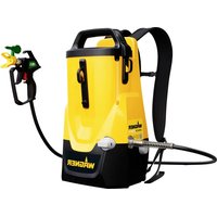
Control Pro 300 Move 18V - Paint spray WAGNER - Free user manual and instructions
Find the device manual for free Control Pro 300 Move 18V WAGNER in PDF.


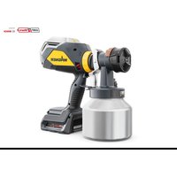
| Product Type | Cordless Airless Spray Gun |
| Brand | WAGNER |
| Model | Control Pro 300 Move 18V |
| Power Supply | Lithium-ion 18 V battery (ProCore 18V, 2.0 Ah) |
| Maximum Pressure | 110 bar (11 MPa) |
| Maximum Flow Rate | 0.9 L/min |
| Tank Volume | 4.7 L |
| Empty Weight | 5.2 kg (pump, hose, gun) |
| Maximum Hose Length | 15 m |
| Nozzle Size | 311 (thin) and 515 (thick) |
| Pump Type | Piston Pump |
| Maximum Product Temperature | 43 °C |
| Sound Pressure Level | 75 dBA (uncertainty K=4 dB) |
| Vibration Level | 3.8 m/s² (K=1.5 m/s²) |
| Usable Materials | Wall paints (water/solvent), lacquers, stains, varnishes, impregnations, oils |
| Non-usable Materials | Abrasive products, silicate paint, acidic/alkaline products, containing acetone or nitro thinner |
| Safety | Trigger lock, mandatory grounding for solvents, decompression procedure, anti-injection protection |
| Maintenance and Cleaning | Cleaning after each use; gun filter, inlet filter, reversible nozzle; rinsing with water or suitable solvent |
| Spare Parts and Repairability | Wear parts: nozzles, filters, valves, pulsation damper; repair by authorized service center |
| Warranty | 3 years + 1 year subject to online registration |
| Compatible Charger | GAL 18V-40 (input 220-240 V~, 50-60 Hz; output 10.8-18 V / 4 A) |
| Charging Time | Approximately 24 min (80%), 35 min (100%) for 2.0 Ah battery |
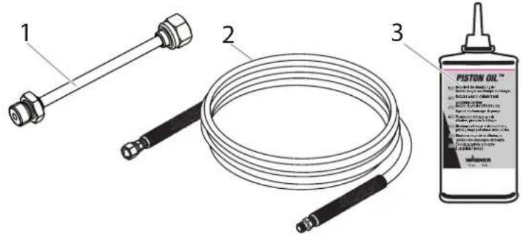
| Optional Accessories | Nozzle extension (30 cm), 7.5 m hose, maintenance oil |
Frequently Asked Questions - Control Pro 300 Move 18V WAGNER
User questions about Control Pro 300 Move 18V WAGNER
0 question about this device. Answer the ones you know or ask your own.
Ask a new question about this device
Download the instructions for your Paint spray in PDF format for free! Find your manual Control Pro 300 Move 18V - WAGNER and take your electronic device back in hand. On this page are published all the documents necessary for the use of your device. Control Pro 300 Move 18V by WAGNER.
USER MANUAL Control Pro 300 Move 18V WAGNER
natural_image
Line drawing of a spray gun with attached hose and handle (no text or symbols)CONTROL PRO 300 MOVE 18V
natural_image
Mechanical assembly diagram showing hands operating a tool with a spring and connecting rod (no text or labels)natural_image
Technical line drawing of a mechanical device with hoses and components (no text or symbols)Tragegurt
natural_image
Mechanical assembly diagram showing two connected components with arrows indicating motion (no text or symbols)natural_image
Diagram of a mechanical device with a lever and control panel (no text or symbols)Farbe vorbereiten
natural_image
Diagram showing a curved arrow pointing downward through a mechanical component (no text or symbols)Pistole entsichern
natural_image
Diagram showing a car wheel and seatbelt mechanism with an upward arrow indicating rotation (no text or symbols)Erdung
⚠️WARNUNG
natural_image
Technical line drawing of a car suspension system with attached components (no text or symbols)natural_image
Simple line drawing of a door with a circular button and a circular symbol with an arrow (no text or labels)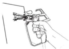
natural_image
Line drawing of a hand holding a spray gun (no text or symbols)Trockenlauf
VORSICHT
natural_image
Two simple line drawings: a box with a circular button and a circular symbol with a right-hand arrow (no text or labels)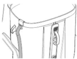
natural_image
Line drawing of a mechanical component with a curved top and attached parts (no text or symbols)Laden
natural_image
Mechanical assembly diagram showing a threaded component with gear and shaft (no text or labels)Konstant leuchtend
Spritzprobe ermittelt were
natural_image
Diagram of a hand holding a car hood with a curved handle and arrow indicating motion (no text or symbols)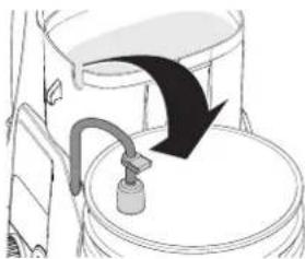
natural_image
Diagram of a toilet with a black arrow indicating flow or direction (no text or symbols)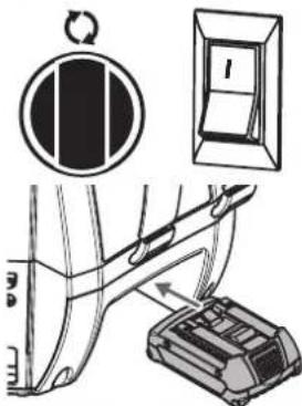
natural_image
Diagram of a car interior showing a curved surface and attached pipes (no text or symbols)natural_image
Diagram of a hand holding a device with directional arrows indicating motion (no text or symbols)
natural_image
Line drawing of a hand holding a tool over a circular object, with no visible text or symbolsnatural_image
Two abstract diagrams: a circular symbol with a vertical bar and a rectangular box with a handle, both without any text or symbols.natural_image
Technical line drawings of mechanical components, showing two assembly steps with no visible text or symbolsnatural_image
Line drawing of a hand holding a handheld device with wires (no text or symbols)
natural_image
Mechanical assembly diagram showing a lever mechanism with rotating arrow (no text or symbols)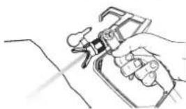
natural_image
Line drawing of a hand holding a handheld device with a tool, no text or symbols present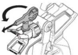
natural_image
Mechanical assembly diagram showing a lever mechanism with rotational motion (no text or symbols)natural_image
Technical illustration of a mechanical device with a lever mechanism and a tool inserted (no text or symbols)natural_image
Line drawing of a handheld device with attached cable (no text or symbols)natural_image
Two circular diagrams: one showing a hand pressing down on a vehicle, the other showing a lock mechanism (no text or symbols)natural_image
Two simple electrical circuit symbols: a circular component with a switch and a rectangular device with a labeled side (no text or labels present)natural_image
Technical line drawing of a mechanical tool with a spring and clamping mechanism (no text or symbols)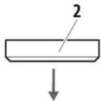
AUSLASSVENTIL ERSETZEN
natural_image
Mechanical assembly diagram showing a tool interacting with a mechanical component (no text or labels visible)natural_image
Technical line drawing of a mechanical component with threaded end and directional arrow (no text or symbols)natural_image
Diagram showing a mechanical component being inserted into a pipe, with an arrow indicating the direction of insertion (no text or symbols present)⚠️WARNUNG
natural_image
Technical line drawing of a mechanical assembly with a drill bit inserted into a component (no text or symbols)natural_image
Illustration of a hand using a tool to lift a cable, next to a close-up of a switch (no text or symbols present)natural_image
Technical line drawing of a mechanical clamp or bracket assembly (no text or symbols)https://go.wagner-group.com/hf-warranty-conditions

Translation of the original operating instructions
Warning!
Attention: Danger of injury by injection!
Airless units develop extremely high spraying pressures.

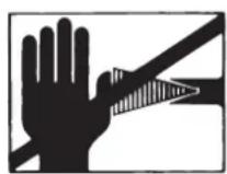
Danger

Never put your fingers, hands or any other parts of the body into the spray jet!
Never point the spray gun at yourself, other persons or animals.
Never use the spray gun without safety guard.
Do not treat a spraying injury as a harmless cut. In case of injury to the skin through coating materials or solvents, consult a doctor immediately for quick and expert treatment. Inform the doctor about the coating material or solvent used.

The operating instructions state that the following points must always be observed before starting up:
- Faulty units must not be used.
- Secure spray gun using the safety catch on the trigger.
- When processing materials containing solvents, the appliance must be earthed.
- Check allowable operating pressure of high-pressure hose and spray gun.
- Check all connections for leaks.

The instructions regarding regular cleaning and maintenance of the unit must be strictly observed.
Before any work is done on the unit or for every break in work the following rules must be observed:
- Release the pressure from spray gun and hose.
- Secure the spray gun using the safety catch on the trigger.
- Switch off unit.
Be safety-conscious !
Congratulations for the purchase of your WAGNER Airless high pressure spray gun.
Read this manual carefully before the initial use of this equipment and observe the safety instructions. Keep manual and safety instructions carefully stored.
You have purchased a quality product which requires careful maintenance and care in order to function perfectly.
Important! After each use, the equipment should be cleaned.
Not cleaning the equipment leads to malfunctioning! For faults caused by crud, no guarantee claim will be granted. In case of malfunctioning, check the cleaned equipment once again prior to sending it in to the service department.
Explanation of symbols used
 Danger Danger | Indicates an immediate danger. Unless avoided, death or serious injuries will result. |
 | Indicates tips for use and other particularly useful information. |
 | Wear suitable ear protection when working. |
 | Wear suitable respiratory equipment when working. |
 | Wear suitable safety gloves when working. |
General Safety Instructions
Warning!

Danger
Read all safety notifications and instructions. Failure to comply with the safety notifications and instructions provided may result in electric shock, fire and/or serious injury. The term "power tool" used below covers both mains-operated power tools (with mains lead) and accumulator-operated power tools (without mains lead).
1. Work area safety
a) Keep work area clean and well lit. Cluttered or dark areas invite accidents.
b) Do not operate power tools in explosive atmospheres, such as in the presence of flammable liquids, gases or dust. Power tools create sparks which may ignite the dust or fumes.
c) Keep children and bystanders away while operating a power tool. Distractions can cause you to lose control.
2. Electrical Safety
a) Power tool plugs must match the outlet. Never modify the plug in any way. Do not use any adapter
plugs with earthed (grounded) power tools. Unmodified plugs and matching outlets will reduce risk of electric shock.
b) Avoid body contact with earthed or grounded surfaces, such as pipes, radiators, ranges and refrigerators. There is an increased risk of electric shock if your body is earthed or grounded.
c) Do not expose power tools to rain or wet conditions. Water entering a power tool will increase the risk of electric shock.
d) Do not abuse the cord. Never use the cord for carrying, pulling or unplugging the power tool. Keep cord away from heat, oil, sharp edges or moving parts. Damaged or entangled cords increase the risk of electric shock.
e) When operating a power tool outdoors, use an extension cord suitable for outdoor use. Use of a cord suitable for outdoor use reduces the risk of electric shock.
f) If operating a power tool in a damp location is unavoidable, use a residual current device (RCD) protected supply. Use of an RCD reduces the risk of electric shock.
3. Personal safety
a) Stay alert, watch what you are doing and use common sense when operating a power tool. Do not use a power tool while you are tired or under the influence of drugs, alcohol or medication. A moment of inattention while operating power tools may result in serious personal injury.
b) Use personal protective equipment. Always wear eye protection. Protective equipment such as dust mask, non-skid safety shoes, hard hat, or hearing protection used for appropriate conditions will reduce personal injuries.
c) Prevent unintentional starting. Ensure the switch is in the off-position before connecting to power source and/or battery pack, picking up or carrying the tool. Carrying power tools with your finger on the switch or energising power tools that have the switch on invites accidents.
d) Remove any adjusting key or wrench before turning the power tool on. A wrench or a key left attached to a rotating part of the power tool may result in personal injury.
e) Do not overreach. Keep proper footing and balance at all times. This enables better control of the power tool in unexpected situations.
f) Dress properly. Do not wear loose clothing or jewellery. Keep your hair, clothing and gloves away from moving parts. Loose clothes, jewellery or long hair can be caught in moving parts.
g) If devices are provided for the connection of dust extraction and collection facilities, ensure these are connected and properly used. Use of dust collection can reduce dust-related hazards.
h) Do not lull yourself into a false sense of security and do not think yourself above the safety rules for electric tools, even if you are familiar with the electric tool following extensive practical experience. Careless use can lead to serious injuries in fractions of a second.
4. Power tool use and care
a) Do not force the power tool. Use correct power tool for your application. The correct power tool will do the job better and safer at the rate for which it was designed.
b) Do not use the power tool if the switch does not turn it on and off. Any power tool that cannot be controlled with the switch is dangerous and must be repaired.
c) Disconnect the plug from the power source and/or the battery pack from the power tool before making any adjustments, changing accessories, or storing power tools. Such preventive safety measures reduce the risk of starting the power tool accidentally.
d) Store idle power tools out of reach of children and do not allow persons unfamiliar with the power tool or these instructions to operate the power tool. Power tools are dangerous in the hands of untrained users.
e) Maintain power tools. Check for misalignment or binding of moving parts, breakage of parts and any other condition that may affect the power tool's operation. If damaged, have the power tool repaired before use. Many accidents are caused by poorly maintained power tools.
f) Keep cutting tools sharp and clean. Properly maintained cutting tools with sharp cutting edges are less likely to bind and are easier to control.
g) Use the power tool, accessories and tool bits etc. in accordance with these instructions, taking into account the working conditions and the work to be performed. Use of the power tool for operations different from those intended could result in a hazardous situation.
h) Keep the handles and grip surfaces dry, clean and free of oil and grease. Slippery handles and grip surfaces hamper safe operation and control of the electric tool in unforeseen situations.
5. Battery tool use and care
a) Recharge only with the charger specified by the manufacturer. A charger that is suitable for one type of battery pack may create a risk of fire when used with another battery pack.
b) Use power tools only with specifically designated battery packs. Use of any other battery packs may create a risk of injury and fire.
c) When battery pack is not in use, keep it away from other metal objects, like paper clips, coins, keys, nails, screws or other small metal objects, that can make a connection from one terminal to another. Shorting the battery terminals together may cause burns or a fire.
d) Under abusive conditions, liquid may be ejected from the battery; avoid contact. If contact accidentally occurs, flush with water. If liquid contacts eyes, additionally seek medical help. Liquid ejected from the battery may cause irritation or burns.
e) Do not use a battery pack or tool that is damaged or modified. Damaged or modified batteries may exhibit unpredictable behaviour resulting in fire, explosion or risk of injury.
f) Do not expose a battery pack or tool to fire or excessive temperature. Exposure to fire or temperature above 130 °C may cause explosion.
g) Follow all charging instructions and do not charge the battery pack or tool outside the temperature range specified in the instructions. Charging improperly or at temperatures outside the specified range may damage the battery and increase the risk of fire.
6. Service
a) Have your power tool serviced by a qualified repair person using only identical replacement parts. This will ensure that the safety of the power tool is maintained.
a) Never service damaged battery packs. Service of battery packs should only be performed by the manufacturer or authorized service providers.
Safety instructions for the charger and battery

Only use the tool with BOSCH AMPShare compatible ProCore 18V batteries with at least 2.0 Ah and suitable chargers. The battery voltage must match the battery charging voltage of the charger. Do not charge non-rechargeable batteries. Otherwise there is a risk of fire and explosion.
- Only use the charger indoors and keep it away from moisture. Water penetrating into a power tool increases the risk of an electric shock.
- Keep the charger clean. There is a risk of electric shock due to contamination.
-
Before every use, check the charger, cable and plug. Do not use the charger if it is damaged. Do not open the charger yourself and only have it repaired by qualified specialist personnel using original spare parts. Damaged chargers, cables and plugs increase the risk of electric shock.
-
Do not operate the charger on easily combustible surfaces (e.g. paper, textiles, etc.) or in combustible environments. There is a risk of fire due to the heating of the charger during charging.
- The battery is delivered partially charged. To ensure full battery performance, fully charge the battery in the charger before first use.
- Only use the battery in the manufacturer's products. This is the only way to protect the battery from dangerous overloading.
- Keep batteries out of the reach of children.
- Do not open the battery. There is a risk of a short circuit.
- Vapours may also escape if the battery is damaged or used improperly. Take in fresh air and consult a doctor if you have any symptoms. The vapours may irritate the respiratory tract.
- If the battery is defective, liquid may leak out and wet adjacent objects. Check affected parts. Clean them or replace them if necessary.
- The battery can be damaged by sharp objects such as nails or screwdrivers or by external force. An internal short circuit may occur and the battery may burn, smoke, explode or overheat.
- Never service damaged batteries. All maintenance of batteries should only be carried out by the manufacturer or authorised service centres.
- Protect the battery from heat, e.g. also from permanent sunlight, fire, dirt, water and moisture. There is a risk of explosion and short circuit.
- Operate and store the battery only at an ambient temperature between -20^ and +50^ . Do not leave the battery in the car in summer, for example. At temperatures < 0^ , performance may be restricted depending on the unit.
- Charge the battery only at ambient temperatures between 0^ and +35^ . Charging outside the temperature range can damage the battery or increase the risk of fire.
- Lithium-ion batteries are subject to the Dangerous Goods Legislation requirements. The batteries are suitable for road-transport by the user without further restrictions. When shipping by third parties (e.g.: by air transport or forwarding agency), special requirements on packaging and labelling must be observed. For preparation of the item being shipped, consulting an expert for hazardous material is required. Dispatch battery packs only when the housing is undamaged. Tape or mask off open contacts and pack up the battery in such a manner that it cannot move around in the packaging. Please also observe the possibility of more detailed national regulations.
Health protection

Caution! Wear breathing equipment: Paint mist and solvent vapors are damaging to health. Always wear breathing equipment and only work in well ventilated rooms or using supplementary ventilating equipment. It is advisable to wear working clothing, safety glasses, ear protection and gloves
Flammable materials

Do not use the spray guns to spray flammable substances.
Explosion protection

Do not use the unit in work places which are covered to the explosion protection regulations.
Danger of explosion and fire through sources of flame during spraying work

There may be no sources of flame such as, for example, open fires, smoking of cigarettes, cigars or tobacco pipes, sparks, glowing wires, hot surfaces, etc. in the vicinity.
Earthing the device

Earth the device with the enclosed earth cable if you are working with materials containing solvents.
Ventilation
Good natural or artificial ventilation must be ensured in order to avoid the risk of explosion or fire and damage to health during spray work.
Secure device and spray gun
All hoses, fittings, and filter parts must be secured before operating spray pump. Unsecured parts can eject at great force or leak a high pressure fluid stream causing severe injury.
Always secure the spray gun when mounting or dismounting the nozzle and in case of interruption to work.
Recoil of spray gun

In case of high operating pressure, pulling the trigger can effect a recoil force of up to 15 N.
If you are not prepared for this, your hand can be thrust backwards or your balance lost. This can lead to injury. Continuous stress from this recoil can cause permanent damage to health.
Max. operating pressure
Max. permissible operating pressure for spray gun, spray gun accessories and high-pressure hose may not fall short of the maximum operating pressure of 110 bar (11 MPa) stated on the unit.
Coating substance
Caution against dangers that can arise from the sprayed substance and observe the text and information on the containers or the specifications given by the substance manufacturer.
Do not spray any liquid of unknown hazard potential.
Do not use paints or solvents that contain halogenated hydrocarbons, such as chlorine, bleach, methylene chloride chloride and trichloroethane. They are not compatible with aluminium. Ask the supplier of the coating about the compatibility of the material with aluminium.
High-pressure hose (safety note)

Danger
Attention, danger of injury by injection! Wear and tear and kinks as well as usage that is not appropriate to the purpose of the device can cause leakages to form in the high-pressure hose. Liquid can be injected into the skin through a leakage.
High-pressure hoses must be checked thoroughly before they are used.
Replace any damaged high-pressure hose immediately. Never repair defective high-pressure hoses yourself!
Avoid sharp bends and folds: the smallest bending radius is about 20 cm.
Do not drive over the high-pressure hose. Protect against sharp objects and edges.
Never pull on the high-pressure hose to move the device. Do not twist the high-pressure hose.
Do not put the high-pressure hose into solvents. Use only a wet cloth to wipe down the outside of the hose.
Lay the high-pressure hose in such a way as to ensure that it cannot be tripped over.
Electrostatic charging of spray guns and the high-pressure hose is discharged through the high-pressure hose. For this reason the electric resistance between the connections of the high-pressure hose must be equal or lower than 197 kΩ/m (60 kΩ/ft.).

For reasons of function, safety and durability, only use genuine WAGNER high-pressure hoses and spray nozzles. For overview see „Spare parts lists“.

The risk of damage rises with the age of the high-pressure hose. Wagner recommends replacing high-pressure hoses after 6 years.
Positioning device

Danger
When working indoors:
Vapors containing solvents may not be allowed to build up in the area of the device. Ensure good ventilation.
When working outdoors:
Vapors containing solvents may not be allowed to blow toward the unit.
Note the direction of the wind.
Maintenance and repairs

Danger
Depressurise the device and remove the battery before carrying out any work on the device.
Cleaning the unit

Danger
Danger of short circuit through penetrating water!
Never spray down the unit with high-pressure or high-pressure steam cleaners.
Cleaning units with solvents

Danger
When cleaning the unit with solvents, the solvent should never be sprayed or pumped back into a container with a small opening (bunghole). An explosive gas/air mixture can be produced. The container must be earthed.
Do not use flammable materials for cleaning purposes.
Earthing of the object
The object to be coated must be earthed.

If liquids collect in the area underneath the outlet valve, this could be due to a leak in the set of pistons. If operations continue, the liquid can leak and dirt might get under the device.
Usabel materials
- Interior wall paint (dispersions and latex paint)
- Water- and solvent-based paints, finishes, primers, stains, staining sealers wood sealer-preservatives and oils.
Unsuitable materials
- Materials that contain highly abrasive components, silicate paint, facade paint, caustic solutions and acidic coating substances.
- Flammable materials, materials containing acetone or cellulose thinner
Field of application
Coating of interior walls as well as small and medium-sized objects outdoors (e.g. garden fences, garage doors, etc.).
Technical data*
| Rechargeable battery (ProCore 18 V, 2.0 Ah): | Li-Ion, 18 V -- 2.0 Ah |
| Charger (AL 1810 CV):Input voltageOutput voltageCharging current | 220-240 V^- , 50-60 Hz;10.8-18 V4000 mA |
| Charging time (rechargeable battery 18 V, 2.0 Ah): | approx. 24 min(80%), 35 min (100%) |
| Protection Class (charger): | /II |
| Maximum pressure 11 MPa (110 bar) | |
| Max. delivery rate 0.9 l/min | |
| Maximum temperature of coating material | 43°C |
| Sound power level**Uncertainty | 75 dBAK= 4 db |
| Sound pressure output**Uncertainty | 88 dBAK= 4 db |
| Vibration***Uncertainty | 3.8 m/ s^2 K = 1.5 m/ s^2 |
| Maximum ambient temperature 40°C | |
| Pump system piston pump | |
| volume upper container, max. 4.7 l | |
| Max. nozzle size 515 HEA | |
| Max. hose length 15 m | |
| Empty weight (pump, hose, gun) 5.2 | kg |
* When using a ProCore 18 V, 2.0 Ah battery and a charger GAL 18V-40
** Measured in accordance with EN 50580
*** Measured in accordance with EN 62841-1
Information about the vibration level
The specified vibration level has been measured according to a standard test procedure and can be used to compare against electric tools.
The vibration level is also for determining an initial assessment of the vibrational strain.
Attention! The vibration emission value can differ from the specified value when the electric tool is actually in use, depending on how the electric tool is being used. It is necessary to specify safety measures to protect the operating personnel. These measures are based on an estimated shutdown during the actual conditions of use (all parts of the operating cycle are taken into consideration here, for example periods when the electric tool is switched off, and, when it is switched on but running without any load).
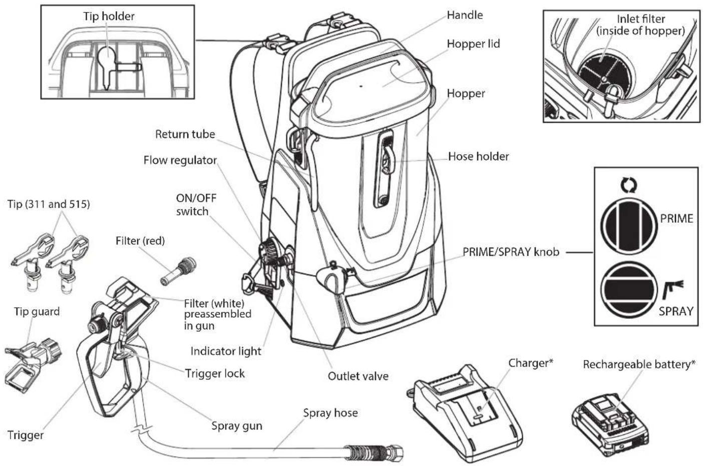
* Not included with all models.
Controls and functions
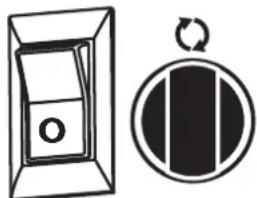
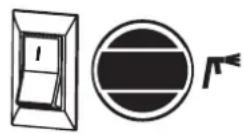
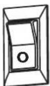
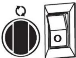
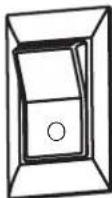
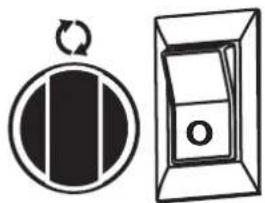
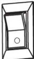
ON/OFF switch The ON/OFF switch turns the unit on and off (O = OFF, I = ON)
PRIME/SPRAY knob The PRIME/SPRAY knob directs fluid to the spray hose when set to SPRAY, or the return tube when set to PRIME.
Flow regulator The flow regulator can be used to adjust the pump's operating speed to suit the material being processed and achieve the desired spray pattern.
Indicator light Displays the battery charge status and error messages
Operating modes
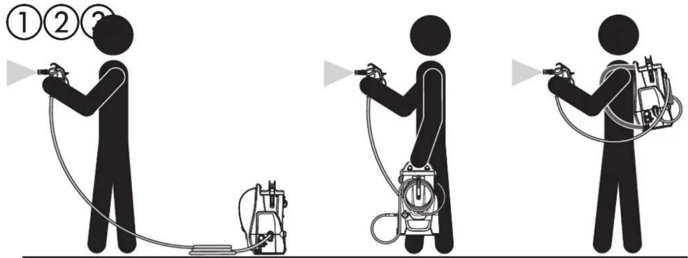
The spray system can be used in three different ways:
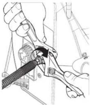
Tools needed for assembly
- Two adjustable wrenches.
WARNING
Only insert the battery when the device is fully assembled.
Hose
Twist the thread at the end of the hose onto the hose connection. Using a wrench, hold the hose connection firmly and tighten the hose with another wrench.
natural_image
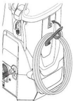
Mechanical assembly diagram showing hands operating a tool with a spring (no text or symbols visible)If the appliance will be carried like a rucksack, open the hose holder and hook in the rolled-up hose.
natural_image
Technical line drawing of a mechanical device with hoses and a central hub (no text or symbols)Carrying strap
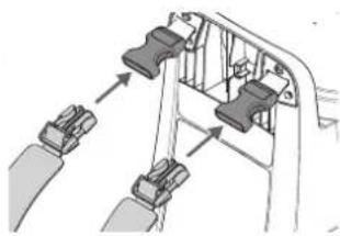
Attach the carrying straps to the quick-release fasteners at the top of the device.
natural_image
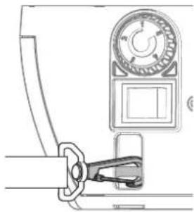
Mechanical assembly diagram showing two clamps inserted into a frame (no text or symbols)Hook the carrying straps onto the bottom of the device.
Hang the device over your shoulders and adjust the straps to suit you.
If the device is tilted too much (e.g. when bending forwards), an acoustic signal sounds.
natural_image
Diagram of a mechanical device with a handle and lever mechanism (no text or symbols)Preparing the paint
To avoid rapid blockage of the nozzle and filter, we recommend stirring and sieving the paint well before spraying. Follow the material manufacturer's instructions.
Select tip and gun filter
Use the proper gun filter based on the tip size being used.
Tip Size Paint Filter
311 For thin materials like acrylic Red paints, primers, stains...
515 For thick materials like white internal emulsions, latex paints, hollow-space sealants..., ...
Locking and unlocking the gun

WARNING

Always lock the trigger off when attaching the spray tip or when the spray gun is not in use.
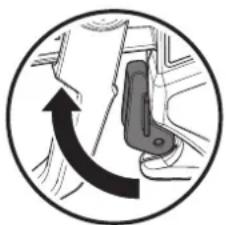
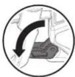
Locking the gun
Fold the trigger lock down to block the trigger.
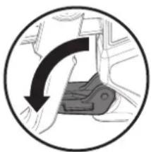
natural_image
Circular diagram showing a curved arrow pointing downward through a mechanical component (no text or symbols)Unlocking the gun
Fold the trigger lock up until it engages to unlock the trigger.
natural_image
Circular diagram showing a hand pressing down on a vehicle's seatbelt, with an arrow indicating clockwise motion (no text or symbols)Earthing
WARNING
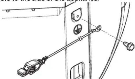
When processing materials containing solvents, the appliance must be earthed.
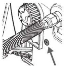
1) Remove the earth screw and screw the enclosed earth cable to the side of the appliance.
natural_image
Technical line drawing of a mechanical assembly with clamps and mounting holes (no text or symbols)2) Attach the earth clamp to a suitable metal installation (e.g. water pipe, radiator, garden fence).
Pressure relief procedure
WARNING
Be sure to follow the pressure relief procedure when shutting the unit off FOR ANY PURPOSE. This procedure is used to relieve pressure from the spray hose.
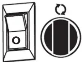
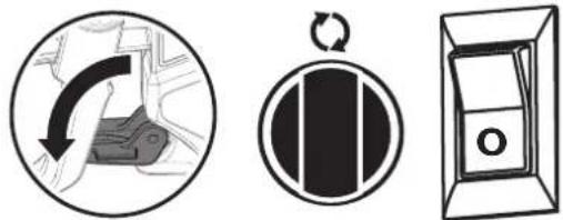
1) Lock the spray gun off and flip the ON/OFF switch to the OFF position.
2) Turn the PRIME/SPRAY knob to PRIME.
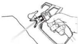
3) Unlock the spray gun and then trigger it onto a scrap piece of wood or cardboard.
4) Lock the spray gun.
natural_image
Two abstract diagrams: a box-like shape with a circular hole and a circular symbol with a black rectangle and arrow (no text or symbols)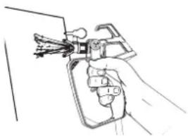
natural_image
Line drawing of a hand holding a spray gun (no text or symbols)Dry running
CAUTION
Operation without liquid leads to increased wear and damages the pump.
Never allow the device to run dry for more than 30 seconds.
One cause of blockages can be a clogged gun or inlet filter/suction filter. Therefore, check and clean the filters regularly.
Refilling the container / bleeding the pump
CAUTION
If the paint in the container runs out, it may be that air is being aspirated into the system. When refilling, the pump must be bled as described below in order to avoid dry running.
1) Switch the pump off immediately.
2) Refill the container.
3) Turn the PRIME/SPRAY knob to PRIME.
4) Switch the pump back on and wait until the paint is flowing out of the return hose.
5) Turn the PRIME/SPRAY switch to the SPRAY position and carry on working.
natural_image
Two simple line drawings: a door with a circular button and a circular symbol with a right-hand arrow (no text or labels)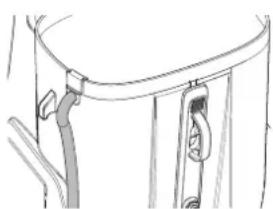
natural_image
Line drawing of a mechanical component with attached parts (no text or symbols)Charging
Before connecting to the mains, make sure that the mains voltage corresponds to the specification on the charger's rating plate.
Explanation of the indicator lights
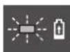
When you insert the battery (1) into the charger (2) the green indicator light (4) will begin to "BLINK". This indicates that the battery is charging.
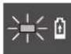
A continuous green indicator light (4) indicates that the battery is fully charged.

A steady red indicator light (3) means that the battery is outside the proper temperature ranges (between 0°C and 35°C). As soon as it falls within the correct temperature range, the charging process will automatically begin.

If the red indicator light (3) is "BLINKING", the contacts on the charger or battery are contaminated, the battery is defective, or the battery is not compatible with the charger. Clean the contacts or replace the battery.
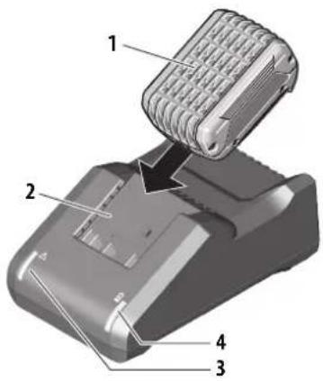
Plug charger cord into a standard power outlet (the charger's green indicator light (4) will switch ON).
- Once the battery is fully charged, remove the battery from the charger.
- Unplug the mains plug of the charger from the socket.
Indicator light
natural_image
Mechanical assembly diagram showing a gear and shaft assembly with an arrow indicating motion direction (no text or labels)Constantly lit = Sufficient battery charge
Flashing (additional = Battery must be charged warning tone)
Preparation of the Coating Material
Using Control Pro 300 interior wall paints, varnishes and glazes can be applied by spraying without diluting them, or by diluting them slightly. Detailed information is available in the technical data sheet of the manufacturer ( Internet download).
- Stir the material thoroughly and dilute it in the container as per the recommended dilution (an agitator is recommended for stirring).
Thinning recommendation
| Glazes, wood preservatives containing solvents or based on water, mordants, oils, disinfection agents, plantprotective agents | undiluted |
| Paints containing solvents and watersoluble paints, primers | dilute by 5 - 10 % |
| Interior wall paint (dispersions and latex paint) | dilute by 0-10 % |

The values in the table are reference values.
Find out how
thinned by testing it.
Make pump ready for operation
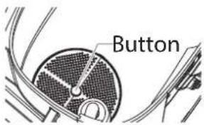
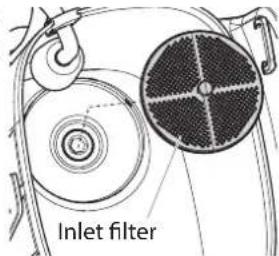
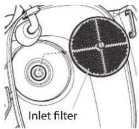
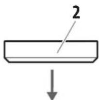
1) Make sure the inlet filter is in place inside the hopper. If it is not, snap in place as shown.
2) Press down the button on the filter once. This will ensure proper operation of the inlet valve.
We recommend performing the following steps with water first of all, in order to check that the system and all connections are watertight.
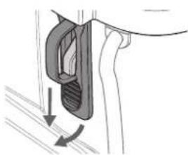
3) Pull the latches down and unhook them to remove the lid.
4) Fill your hopper with the material you plan to spray. Do not exceed the fill line as shown. Pull the return hose out of the container and hold it over an empty container.
5) Turn the PRIME/SPRAY knob to PRIME.
6) Insert the battery and set the ON/OFF switch to the ON position.
7) Slowly turn the speed control clockwise to 2.
8) Check that the material is flowing through the return tube.
9) Switch the pump to OFF.
natural_image
Diagram of a mechanical component with directional arrows indicating motion (no text or symbols)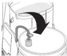
natural_image
Diagram of a toilet with a curved pipe and lid, showing airflow direction (no text or symbols)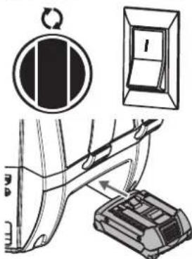
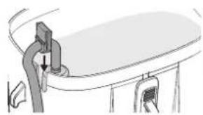
10) Reinsert the return hose into the container. The sealing grommet must be seated correctly in the slot.
11) Hook in the two latches and replace the lid on the container.

The cover does not close airtight. Therefore, do not tilt the device when filled.
natural_image
Diagram of a curved surface with a vertical pipe and attached bracket, showing no text or symbols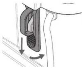
natural_image
Diagram of a hand holding a car with a curved handle and directional arrows indicating motion (no text or symbols)Suck in material
Perform the following steps, without the spray tip mounted to the gun.
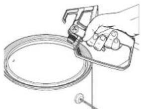
1) Unlock the spray gun and turn the PRIME/SPRAY knob to PRIME.
2) Using the metal thread on the gun, touch the edge of a metal container to earth the gun.
3) Actuate the trigger and KEEP IT PRESSED.
4) Switch the pump on. Slowly turn the speed control clockwise to 2.

WARNING

Keep hands clear from fluid stream.
5) While holding the trigger, turn the PRIME/SPRAY knob to SPRAY. Hold the trigger until all air, water, or solvent is purged from the spray hose and paint is flowing freely.
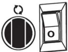
6) Release trigger, turn the PRIME/SPRAY knob to PRIME and turn pump OFF.

natural_image
Line drawing of a hand using a spray gun to clean a circular object (no text or symbols)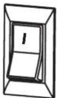

natural_image
Two simple line diagrams: a circular symbol with a vertical bar and a rectangular box with a handle, both without any text or symbols.7) Trigger the gun into the waste container once more to be sure that no pressure is left in the hose.
8) Lock the spray gun off.
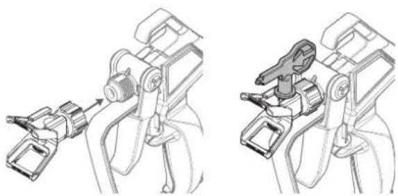
9) Thread the spray tip assembly onto the gun. Tighten by hand.
10) Insert spray tip (tip pointing in the spray direction).
natural_image
Technical line drawing of two mechanical assembly components (no text or symbols)Your device is now ready for operation.
Practice
CAUTION
Be sure that the paint hose is free of kinks and clear of objects with sharp cutting edges.
1) Switch the pump ON and turn the PRIME/SPRAY knob to SPRAY.
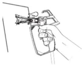
2) When the motor shuts off, unlock the spray gun and spray a test area to check the spray pattern.
When enough pressure has built up in the hose, the motor will shut off automatically. The motor will cycle on and off automatically as it needs pressure.
natural_image
Line drawing of a hand holding a handheld device (no text or symbols)
Good spray pattern

natural_image
Solid black rectangle with horizontal white stripes (no text or symbols)Bad spray pattern (tailing)
If your pattern is tailing, your spray tip might have an obstruction, your spray gun filter might be clogged or your spray tip might be worn or color is diluted too few. Refer to Spraying Troubleshooting on the next page.
Spraying technique
The key to a good paint job is an even coating over the entire surface. This is done by using even strokes. Follow the TIPS, below.
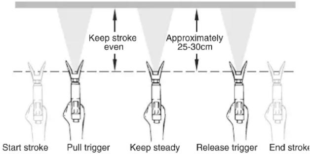
TIP: Keep your arm moving at a constant speed and keep the spray gun at a constant distance from the surface. The best spraying distance is 25 to 30 cm between the spray tip and the surface.
Even coat throughout

Keep stroke smooth and at an even speed.
TIP: Keep the spray gun perpendicular to the surface, otherwise one end of the pattern will be thicker than the other.
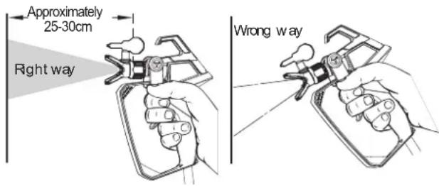
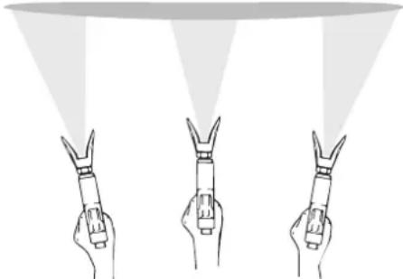
TIP: Keep the spray gun at right angles to the surface. This means moving your entire arm back and forth rather than just flexing your wrist.
Light Coat Light Heavy Coat
natural_image
Three hand gestures with pointed tips under a spotlight beam (no text or symbols)Do not flex wrist while spraying.
TIP: The spray gun should be triggered by turning it on and off with each stroke. Do not trigger the gun during the middle of a stroke. This will result in an uneven spray and splotchy coverage.
Proper way to trigger the spray gun
ADDITIONAL TIPS
Overlap each stroke by about 30%. This will ensure an even coating.
When you stop painting, follow PRESSURE RELIEF PROCEDURE and unplug electrical cord.
Keep the hopper lid placed on the hopper during spraying.
This will prevent debris from falling into your spray material.
IF YOU EXPECT TO BE AWAY FROM YOUR SPRAYER FOR MORE THAN ONE HOUR, FOLLOW THE SHORT-TERM STORAGE PROCEDURE DESCRIBED IN THE STORAGE SECTION OF THIS MANUAL (page 37).
The following is a short list of minor difficulties you might encounter while spraying. If any of these occur, it will reduce the flow of material, making your spray pattern poor, or material will fail to spray from the gun.
Follow the guidelines on this page to correct any one of these problems.
Unclogging the spray tip

WARNING

Do not attempt to unclog or clean the tip with your finger.
CAUTION
Do not use a needle or other sharp pointed instrument to clean the tip. The hard tungsten carbide can chip.
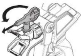
If the spray pattern becomes distorted or stops completely while the gun is triggered, follow these steps:
1) Turn the pump off, and release the trigger and lock the gun off.
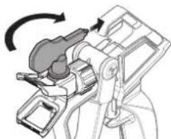
2) Rotate the reversible tip arrow 180^ so that the point of the arrow is toward the rear of the gun.
Under pressure, the spray tip may be very difficult to turn. Turn the PRIME/SPRAY knob to PRIME and trigger the gun. This will relieve pressure and the tip will turn more easily.
3) Turn the PRIME/SPRAY knob to SPRAY.
natural_image
Mechanical assembly diagram showing a clamping mechanism with rotating arrow (no text or symbols)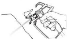
natural_image
Line drawing of a hand holding a small mechanical device (no text or symbols)4) Unlock the gun and squeeze the trigger, pointing the gun at a scrap piece of wood or cardboard. This allows pressure in the spray hose to blow out the obstruction. When the nozzle is clean, paint will come out in a high pressure stream.
If paint still will not spray from the spray tip, follow the steps on the next column.
5) Release the trigger and lock the gun off.
6) Reverse the tip so the arrow points forward again (SPRAY position).
7) Unlock the gun and resume spraying.
natural_image
Mechanical assembly diagram showing a lever mechanism with rotational motion (no text or symbols)Unclogging the spray gun filter
This filter must be cleaned every time you use your sprayer. When using thicker paints, the filter might need to be cleaned more often.
1) Perform Pressure Relief Procedure (page 30).
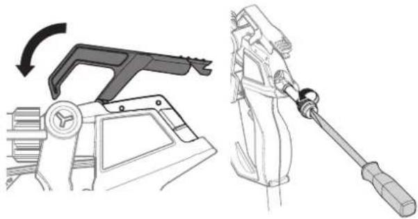
2) Pull the hook upwards and fold the filter cover forwards.
3) Unscrew the filter from the gun using a slotted screwdriver.
natural_image
Technical illustration of a mechanical device with a lever mechanism and a tool inserted (no text or symbols)When cleaning filter, look for sediments in the spraying material you are using. Refer to Paint Straining, (page 30).
4) Inspect the filter for holes. Replace if holes are found.
CAUTION
NEVER POKE THE FILTER WITH A SHARP INSTRUMENT!
5) Insert the filter back into the gun and tighten it with a slotted screwdriver.
6) Fold the filter cover back down and press it into place.
Unclogging the inlet filter
1) Perform Pressure Relief Procedure, (page 30).
2) Empty the hopper of all spraying material (see Emptying the Hopper, page 35).
3) Remove the inlet filter from the hopper. A pair of pliers may be needed to loosen the filter.
4) Clean the inlet filter using the appropriate cleaning solution (warm, soapy water).
5) Replace filter.
If after having completed all of the steps on this page you are still experiencing problems spraying, refer to the TROUBLESHOOTING page (page 39)
Important cleaning notes
READ THESE NOTES AND WARNINGS BEFORE YOU START TO CLEAN YOUR SPRAYER!
- Thorough cleaning and lubrication of the sprayer is the most important step you can take to ensure proper operation after storage.
- Clean the spray device and components with a suitable cleaning agent (e.g. warm soapy water for water-soluble spray materials).
- Make sure to dispose cleaning solution properly when finished cleaning your sprayer.
- Remove the carrying straps for easier cleaning.
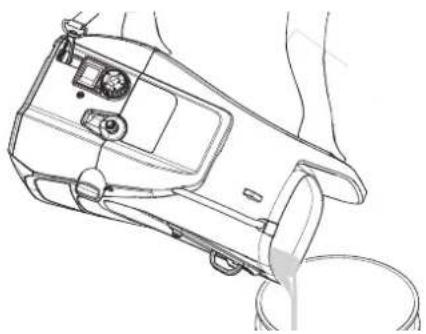
Emptying the hopper
WARNING
The unit, when filled with spraying material, can be heavy. Make sure to lift with your legs and not your back in order to reduce the risk of injury.
CAUTION
Make sure your floors and furnishings are protected with drop cloths to avoid property damage.
1) Perform all the steps of the Pressure Relief Procedure (page 30).
2) Remove the lid from the hopper.
3) Hold the device by the two handles on the left and right.
4) Hold the appliance by the two handles and pour the contents of the container into the original container.
natural_image
Line drawing of a handheld device with a cable inserted, showing internal components and wiring (no text or symbols)Purging the paint hose
These steps will allow you to recover excess paint left over in the paint hose.
1) Lock the gun, remove spray tip assembly, and turn the PRIME/SPRAY knob to PRIME.

natural_image
Two circular diagrams: one showing a hand pressing a curved arrow, the other showing a black rectangular object with a circular arrow (no text or symbols)2) Fill the hopper with the appropriate cleaning solution.
3) Using the metal thread on the gun, touch the edge of a metal container to earth the gun.
4) Unlock the gun, actuate the trigger and hold it down.
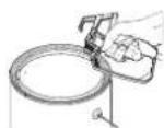
5) While holding the trigger, turn the pump ON, and turn the PRIME/SPRAY knob to SPRAY.
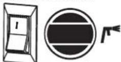
Let the pump run until all paint is purged from the hose and cleaning solution is coming out of the gun.
6) Release the trigger and turn the PRIME/SPRAY knob to PRIME.
7) Hold the spray gun with the thread on the edge of another metal container and then actuate and hold down the trigger.
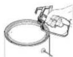
8) Turn the PRIME/SPRAY knob to SPRAY and trigger the gun until the fluid coming out of the gun is clear.
You might need to add more cleaning solution to the hopper.
9) Turn the PRIME/SPRAY knob to PRIME and trigger gun once more to relieve pressure.
Rinsing the hopper
1) Thoroughly rinse out the hopper using the appropriate cleaning solution.
Make sure you do not drip any cleaning solution into the motor housing.
2) Remove the inlet filter from the bottom of the hopper and clean. You may need to use a screwdriver to pry the filter loose.
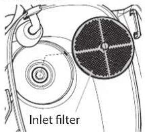
3) Replace the filter and properly dispose of the cleaning solution.
Flushing the sprayer
1) Fill the hopper with NEW cleaning solution.
2) Turn the PRIME/SPRAY knob to PRIME, turn the pump to ON.
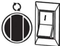
natural_image
Two simple diagrammatic symbols: a circular arrow with a rectangular bar and a rectangular door with a handle (no text or labels)3) Let the pump circulate the cleaning solution out the return tube for 2-3 minutes.
4) Turn the pump OFF.
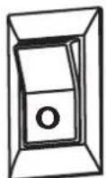
5) Properly dispose of cleaning solution and move on to Cleaning the Spray Gun Components, next page.
Cleaning the spray gun components
1) Perform Pressure Relief Procedure, page 30.
2) Remove filter from spray gun (refer to Unclogging the Spray Gun Filter, page 34).
3) Remove spray tip from spray guard assembly.
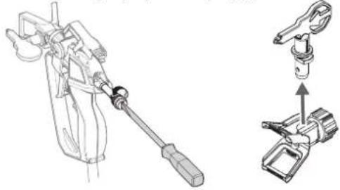
natural_image
Technical line drawing of a mechanical tool and its assembly (no text or symbols)4) Clean spray tip and filter with a soft-bristled brush and the appropriate cleaning solution. Take care to remove the holder in the rear section of the spray nozzle set and clean it.
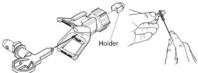
5) Pour a few drops of oil into the gun.
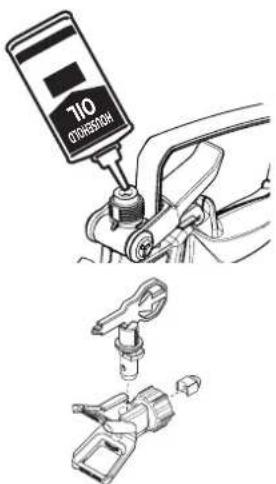
6) Reassemble spray gun: - Insert the gun filter and tighten it with a slotted screwdriver. - Install the spray nozzle and holder. Place the nozzle holder on the gun and tighten it.
IMPORTANT!
If you cleaned your pump, it is recommended that you flush the pump again using warm, soapy water to prepare it for storage. Repeat Flushing the Pump instructions.
Cleaning the inlet valve
Cleaning or servicing the inlet valve may be required if the unit has priming problems. This may be caused by improper cleaning and/or storage.
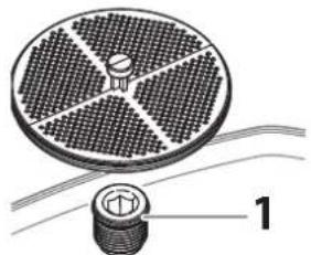
1) Remove the inlet filter from the bottom of the hopper.
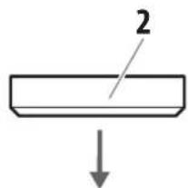
2) Loosen and remove the inlet valve housing (1) with an Allen key (8 mm). 3) Remove the valve seat (2), ball (3), spring (4) and O-ring seal (5) with a suitable tool (e.g. needle-nose pliers, tweezers).
Tip: alternatively, turn the device upside down with the cover on and release the parts by tapping on the underside of the device.
4) Check all parts and the valve area (6) in the container and clean thoroughly. Replace damaged parts.
5) Ensure the O-ring seal on the inlet valve housing (1) is well lubricated.
6) Replace all parts as shown in the illustration. The conical side of the inlet valve seat (2) must point downwards.
7) Securely re-tighten the inlet valve housing (1) with an Allen key (8 mm).
natural_image
Diagram of a circular component with radial patterns and a small inset bolt, connected by wires (no text or symbols)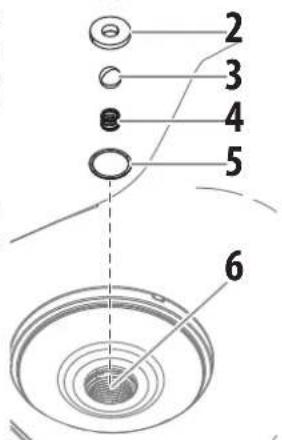
Replacing the outlet valve
Replacement of the outlet valve may be necessary if your spray performance remains poor after having performed all the steps contained in the Spraying Troubleshooting section of this manual.
1) Remove the high-pressure hose from the outlet valve using two spanners.
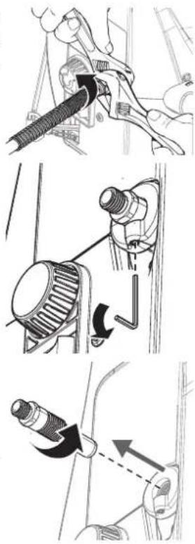
2) Loosen the screw (2.5 mm Allen key) on the bottom of the outlet valve, but do not remove it.
3) Remove the outlet valve from the base unit using a spanner.
4) Check the outlet valve and clean thoroughly (especially the ball seat on the back). Replace if necessary.
5) Inspect the inside of the outlet valve housing. Remove any accumulated paint.
6) Reinsert the new or cleaned outlet valve (tighten into outlet valve housing with an adjustable wrench).
7) Re-tighten the screw.
WARNING
Securely tighten the screw to ensure grounding of the hose and gun.
Replacing the pulsation damper
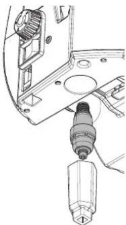
If the spray jet begins to pulsate after some time, the pulsation damper needs to be replaced (service set 2465928).
natural_image
Technical line drawing of a mechanical assembly with a drill bit and tool (no text or symbols)1) Unscrew the pulsation damper from the hole in the underside of the device using the tool included in the set.
2) Insert the new pulsation damper and screw it tight.
SHORT-TERM STORAGE
Shutdown
1) Perform all the steps of the PRESSURE RELIEF PROCEDURE (page 30).
natural_image
Three-step diagram showing a circular process with a curved arrow, a vertical bar, and a door with an open lid (no text or symbols)2) Pour 1/2 cup water slowly on top of the paint to prevent it from drying. Replace the hopper lid.
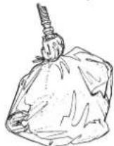
3) Wrap the spray gun assembly in a damp cloth and place it in a plastic bag. Seal the bag shut.
4) Unplug the sprayer.
5) Place the sprayer in a safe place out of the sun for shortterm storage.
Startup
1) Remove the gun from the plastic bag and stir the water into the paint.
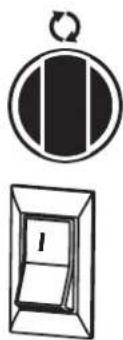
2) Check to be sure the PRIME/SPRAY knob is set to PRIME.
3) Plug sprayer in and turn the switch to ON.
4) Turn the PRIME/SPRAY knob to SPRAY.
5) Test the sprayer on a practice piece and begin spraying.
natural_image
Simple line drawing of a circular object with vertical bars and a rectangular box containing a letter 'I' (no text or symbols)
Preparing the sprayer for longterm storage
1) Make sure you have already completed the Cleanup steps on pages 35-36.
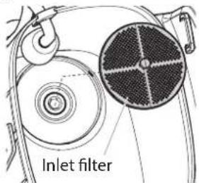
2) Remove the inlet filter. You may need to use a screwdriver to pry it loose.
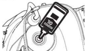
3) Pour approximately 10 ml of light household oil into the inlet valve.
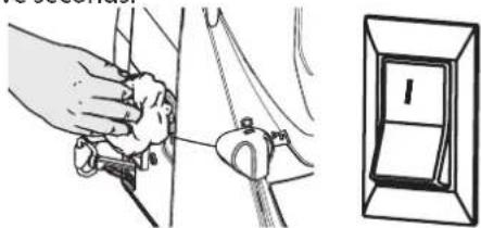
4) Remove hose from outlet valve, place a rag over the outlet valve, and turn the switch ON. Let the unit run for five seconds.
natural_image
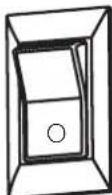
Illustration of a hand using a tool to lift a cable or cable, next to a close-up of a switch (no text or symbols present)5) Switch the pump OFF.
6) Reinstall the inlet filter and press the button on the filter.

7) Wipe the entire unit, hose and gun with a damp cloth to remove accumulated paint.
Storage/Conservation of the gun
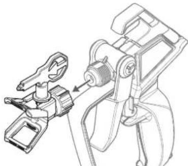
1) Remove the nozzle and nozzle holder from the gun.
natural_image
Technical line drawing of a mechanical clamp or bracket assembly (no text or symbols)2) Pour a few drops of oil into the gun.
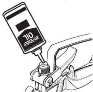
3) Reassemble the gun.
WARNING
Before servicing, always release system pressure by following PRESSURE RELIEF PROCEDURE (page 30).
PROBLEM CAUSE SOLUTION
| A. The sprayer does not start. | 1) Battery flat, faulty or incompatible2) The ON/OFF switch is set to OFF.3) The sprayer shuts off while still under pressure.4) There is a problem with the motor. | 1) Charge or replace2) Turn the ON/OFF switch to ON.3) Motor will cycle ON and OFF while spraying as it needs pressure. This is normal. Resume painting.4) Take sprayer to Wagner Authorized Service Center. |
| B. The sprayer starts but does not draw in paint. | 1) The unit is not primed.2) The hopper is empty.3) The inlet filter is clogged.4) The inlet or outlet valve is stuck.5) The inlet valve is worn or damaged.6) The PRIME/SPRAY valve is plugged. | 1) Set the device to PRIME and switch it on until paint flows out of the return pipe hose.2) Refill the hopper. Set the device to PRIME and switch it on until paint flows out of the return pipe hose.3) Clean the inlet filter.4) Clean the inlet and outlet valves and replace any worn parts. Inlet may be stuck from old paint. Push inlet filter tab to release.5) Replace the inlet valve.6) Take sprayer to Wagner Authorized Service Center. |
| C. The sprayer draws up paint but the pressure drops when the gun is triggered. | 1) The spray tip is worn.2) The inlet filter is clogged.3) The gun or spray tip filter is plugged.4) The paint is too heavy or coarse.5) The outlet valve assembly is dirty or worn.6) The inlet valve assembly is damaged or worn. | 1) Replace the spray tip with a new tip.2) Clean the inlet filter.3) Clean or replace the proper filter. Always keep extra filters on hand.4) Thin or strain the paint.5) Clean or replace the outlet valve assembly.6) Replace the inlet valve. |
| D. The sprayer has switched off during operation (indicator light flashes) | 1) Device overloaded / motor overheated 1) | Switch off the appliance, depressurise and allow to cool down. If the problem persists, contact Wagner Service. |
| E. The PRIME/SPRAY valve is on SPRAY and there is flow through the return tube. | 1) The PRIME/SPRAY valve is dirty or worn. 1) | Take sprayer to Wagner Authorized Service Center. |
| F. The spray gun leaks. | 1) Internal parts of the gun are worn or dirty. | 1) Replace the spray gun with a new one. |
| G. The tip assembly leaks. 1) | The tip was assembled incorrectly.2) A seal is worn. | 1) Check the tip assembly and assemble properly.2) Replace the seal. |
| H. The spray gun will not spray. | 1) The spray tip or the gun filter is plugged.2) The spray tip is in the CLEAN position.3) PRIME/SPRAY knob not set on SPRAY. | 1) Clean the spray tip or gun filter. Review Unclogging the Spray Tip.2) Put the tip in the SPRAY position.3) Turn the PRIME/SPRAY knob to SPRAY. |
| I. The paint pattern is tailing. 1) | The gun, the tip, or the inlet filter is plugged.2) The tip is worn.3) The paint is too thick.4) Pressure loss. | 1) Clean the filters and strain the paint.2) Replace the spray tip.3) Thin the paint.4) Refer to Causes and Solutions for problem C. |
| J. Spray jet is uneven/pulsating | 1) Pulsation damper faulty | 1) Replace pulsation damper (see Maintenance chapter) |
SPRAY GUN
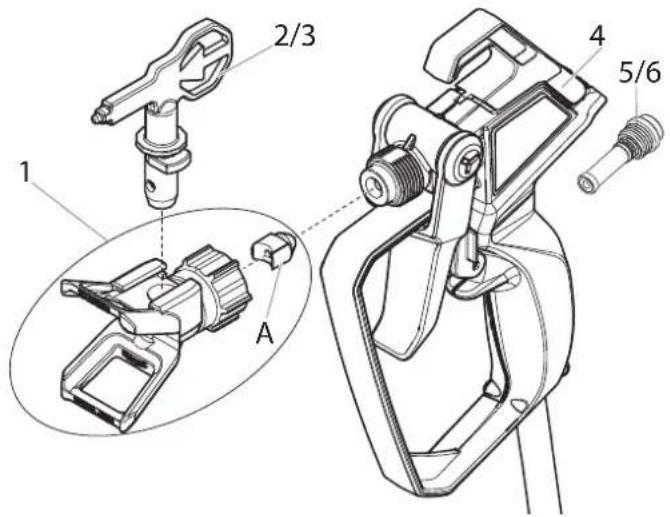
Item Part # Description Quantity
1 2450287 Nozzle holder (incl. seal A) 1
2* 0517 311 Tip 311 (for thick materials) 1
3* 0517 515 Tip 515 (for thin materials) 1
4* 2450284 Complete gun assembly (incl pos. 1,6)
5* 2450276 Filter red (incl. seal A) 2
6* 2450281 Filter white (incl. seal A) 2
* Wear parts: Not covered by guarantee

If using another nozzle, the right filter must also be used.
Tip 311 → Filter red Tip 515 → Filter white
SPRAYER
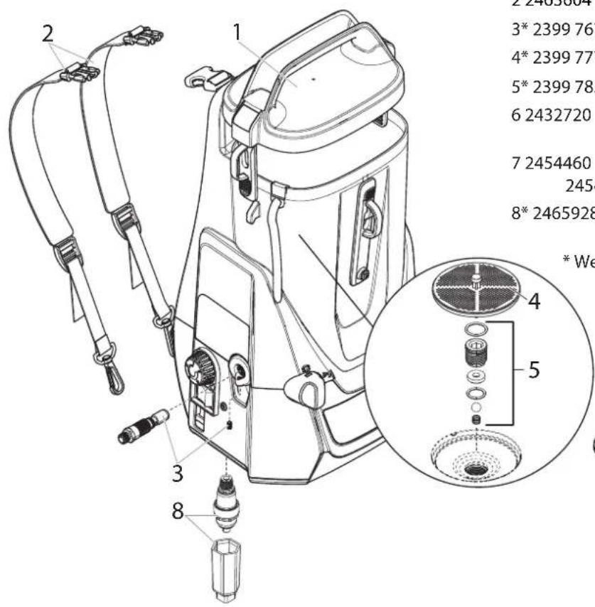
| Item | Part # | Description | Quantity |
| 1 | 2463792 | Hopper lid | 1 |
| 2 | 2463604 | Carrying straps | 1 |
| 3* | 2399 767 | Outlet valve kit | 1 |
| 4* | 2399 777 | Inlet filter | 1 |
| 5* | 2399 783 | Inlet valve kit | 1 |
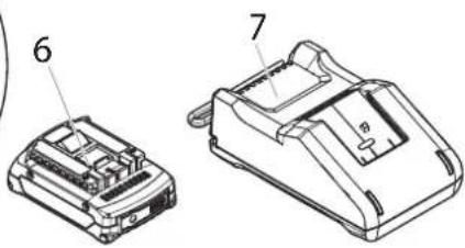
| 6 | 2432720 | Rechargeable battery(ProCore 18 V, 2.0 Ah) | 1 |
| 7 | 2454460 | Charger EU (GAL 18V-40) | 1 |
| 2454650 | Charger UK (GAL 18V-40) | 1 | |
| 8* | 2465928 | Pulsation damper service set(incl. tools) | 1 |
* Wear parts: Not covered by guarantee
Accessories (not included in the delivery)
Item Part # Description Quantity
| 1 2441588 | Gun extension (30 cm) | 1 |
| 2 2398 073 | 7.5 m spray hose 1 | |
| 3 508 619 | Oil (118ml) | 1 |
3 + 1 year guarantee on this WAGNER DIY product
In addition to the statutory warranty for this product, J. Wagner GmbH, based in 88677 Markdorf, Germany, grants you a guarantee (device guarantee) of 36 months for this product. This guarantee is extended by a further 12 months if the product is registered within 28 days of purchase on the Internet at https://go.wagner-group.com/3plus1.
The guarantee includes the free repair of defects which are demonstrably caused by the use of unsuitable materials in the product's manufacture or by assembly errors, as well as the free replacement of faulty components provided there are no guarantee exclusions.
The statutory material defect rights to which you as the purchaser are entitled for the intended purpose from the time of handover of the purchased item are not restricted by the guarantee. The guarantee, along with your statutory warranty rights, will expire if the device has been opened by persons other than authorised WAGNER service personnel. The detailed guarantee conditions can be obtained on request from our authorised WAGNER partners (see website or operating instructions) or in text form on our website:
https://go.wagner-group.com/hf-warranty-conditions

- Modifications reserved -
Environmental protection

At the end of its service life, the appliance, including accessories and packaging, must be recycled in an environmentally friendly manner. Separate packaging materials by type and put them in the recyclables collection. Old appliances and rechargeable batteries/batteries must not be disposed of with household waste. Help protect the environment by taking the appliance and the battery to a local disposal point, contact our customer service team or make enquiries at a specialist shop.
Important Note regarding Product Liability!
According to an EU directive, the manufacturer is only liable without limitation for faults in the product if all parts come from the manufacturer or have been approved by the manufacturer and have been mounted to the device and are operated properly. If third-party accessories or spare parts are used, the manufacturer is exonerated wholly or partly from his/her liability if use of the third-party accessories or spare parts have caused a defect in the product.
EU Declaration of conformity
We declare under sole responsibility that this product conforms to the following relevant stipulations:
2006/42/EC, 2014/30/EU, 2014/35/EU, 2011/65/EU, 2012/19/EU
Applied harmonised norms:
EN 62841-1, EN 50580, EN 60335-1, EN 60335-2-29, EN 62133-2, EN IEC 55014-1, EN IEC 55014-2, EN 62233, EN IEC 61000-3-2, EN 61000-3-3
The EU declaration of conformity is enclosed with the product.
If required, it can be re-ordered using order number 2456995.
UKCA Declaration of conformity
We declare under sole responsibility that this product conforms to the following relevant regulations:
Supply of Machinery (Safety) Regulations 2018
Electrical Equipment (Safety) Regulations 2016
Electromagnetic Compatibility Regulations 2016
The Restriction of the Use of Certain Hazardous Substances in Electrical and Electronic Equipment Regulations 2012
The Waste Electrical and Electronic Equipment Regulations 2013
Applied harmonised standards
BS EN 62841-1, BS EN 50580, BS EN 62133-2, BS EN 60335-1, BS EN IEC 60335-2-29, BS EN IEC 55014-1, BS EN IEC 55014-2,
BS EN IEC 61000-3-2, BS EN 61000-3-3
situation inattendue.
natural_image
Mechanical assembly diagram showing hands operating a tool with a spring (no text or symbols visible)natural_image
Technical line drawing of a mechanical device with hoses and components (no text or symbols)Sangle
natural_image
Mechanical assembly diagram showing two connected components with arrows indicating direction (no text or symbols)natural_image
Line drawing of a mechanical clamp or bracket with a rotary dial (no text or symbols)natural_image
Circular diagram showing a curved arrow pointing downward on a mechanical component (no text or symbols)natural_image
Circular diagram showing a hand pressing down on a car seatbelt, with an arrow indicating clockwise motion (no text or symbols)Mise à la terre

natural_image
Technical line drawing of a car suspension system with attached components (no text or symbols)natural_image
Diagram showing a door with a circular button and a circular symbol with a refresh arrow (no text or labels)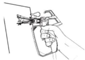
natural_image
Line drawing of a hand holding a pair of pliers (no text or symbols)natural_image
Simple line drawing of a device with a circular button and a circular symbol (no text or labels)natural_image
Line drawing of a mechanical component with no visible text or symbolsChargement
natural_image
Mechanical assembly diagram showing a gear and shaft assembly with an arrow indicating direction (no text or labels)Allumé en continu
natural_image
Diagram of a mechanical component with directional arrows indicating motion (no text or symbols)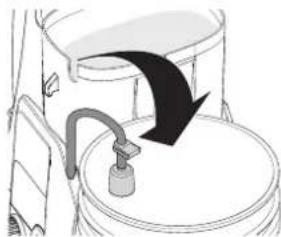
natural_image
Diagram of a toilet with a black arrow indicating flow direction (no text or symbols)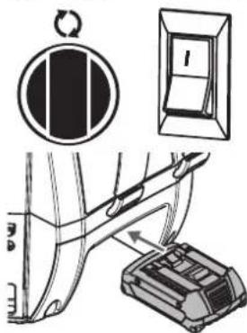
natural_image
Simple line drawing of a car interior with a valve and door (no text or symbols)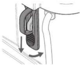
natural_image
Diagram of a mechanical component with directional arrows indicating motion (no text or symbols)Aspirer le produit
natural_image
Hand holding a tool applying material to a circular component (no text or symbols visible)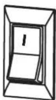

natural_image
Two abstract diagrams: a circular symbol with a rotation arrow and a rectangular box with internal structure (no text or symbols)natural_image
Technical line drawings of mechanical components, showing two views of a device with no visible text or symbolsnatural_image
Line drawing of a hand holding a tool with a handle (no text or symbols)
Bonne forme de jet

natural_image
Abstract black and white striped pattern with no text or symbolsFormation de filaments
natural_image
Mechanical assembly diagram showing a clamping mechanism with rotating arrow (no text or symbols)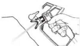
natural_image
Line drawing of a hand holding a handheld device (no text or symbols)natural_image
Mechanical assembly diagram showing a rotating lever mechanism (no text or symbols)natural_image
Technical illustration of a mechanical device with a lever mechanism and a tool inserted (no text or symbols)natural_image
Line drawing of a handheld device with attached cables and control panel (no text or symbols)natural_image
Two circular diagrams: one showing a hand pressing down on a vehicle, the other showing a black rectangular sign with vertical stripes (no text or symbols)natural_image
Technical line drawing of a mechanical device with a tool and assembly detail (no text or symbols)natural_image
Medical illustration showing a surgical procedure with an arrow indicating direction (no text or labels present)natural_image
Technical line drawing of a mechanical component with threaded end and curved arrow indicating motion (no text or symbols)natural_image
Diagram showing a mechanical component with an arrow indicating direction, no text or symbols presentAVERTISSEMENT
natural_image
Technical line drawing of a mechanical assembly with a drill bit inserted into a component (no text or symbols)natural_image
Illustration of a hand using a tool to lift a cable, next to a switch labeled 'I' (no text or symbols on the diagram itself)5) Mettre la pompe hors tension (O).
natural_image
Technical line drawing of a mechanical clamp or bracket assembly (no text or symbols)PROBLÈME CAUSE SOLUTION
https://go.wagner-group.com/hf-warranty-conditions

natural_image
Technical line drawing of a mechanical assembly with hands operating a tool (no text or symbols visible)natural_image
Technical line drawing of a mechanical device with hoses and a coiled cable (no text or symbols)Draagriem
natural_image
Mechanical assembly diagram showing two connected components with arrows indicating motion (no text or symbols)natural_image
Diagram of a mechanical device with a handle and control panel (no text or symbols)Verf voorbereiden
natural_image
Diagram showing a curved arrow indicating direction, enclosed in a circle (no text or symbols)Pistool vrijgeven
natural_image
Circular diagram showing a hand pressing down on a car seatbelt, with an arrow indicating clockwise motion (no text or symbols)Aarding

natural_image
Technical line drawing of a car suspension system with attached sensors and wiring (no text or symbols)natural_image
Simple line drawing of a door with a circular button and a circular switch symbol (no text or labels)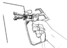
natural_image
Hand holding a spray gun with multiple blades (no text or symbols visible)Droogloop

VOORZICHTIG
natural_image
Simple line drawing of a door with a circular button and a circular symbol with an arrow (no text or labels)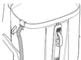
natural_image
Line drawing of a mechanical component with no visible text or symbolsOpladen
natural_image
Mechanical assembly diagram showing a gear and shaft assembly with an arrow indicating direction (no text or labels)Constant brandend
= Voldoende acculading
Knippert (extra
natural_image
Diagram of a mechanical component with directional arrows indicating motion or force (no text or symbols)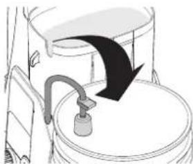
natural_image
Diagram of a toilet with a bucket and pipe, showing airflow direction (no text or symbols)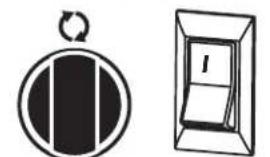
natural_image
Two abstract geometric symbols: a circular arrow icon and a rectangular box with the number 1 (no text or labels)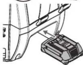
natural_image
Technical line drawing of a mechanical component with a bracket and housing (no text or symbols)natural_image
Diagram of a car interior showing a valve inserted into a seat (no text or symbols present)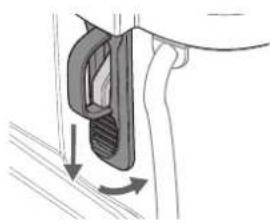
natural_image
Diagram of a mechanical component with directional arrows indicating motion or force (no text or symbols)Materiaal aanzuigen
natural_image
Illustration of a hand holding a tool next to a circular symbol with a diagonal stripe and a ring, next to a small mechanical component (no text or symbols present)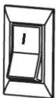

natural_image
Two abstract diagrams: a circular symbol with a diagonal bar and a rectangular box with a handle, next to a circular button with a minus sign (no text or symbols present)natural_image
Technical line drawing of mechanical assembly with two views (no text or symbols)natural_image
Illustration of a hand holding a tool with a key, next to a circular emblem and a rectangular panel (no text or symbols)
Goed spuitresultaat

natural_image
Solid black rectangle with horizontal white stripes (no text or symbols)Slecht spuitresultaat (strepen)
natural_image
Mechanical assembly diagram showing a rotating component with directional arrows (no text or symbols)3) De PRIME/SPRAY-schakelaar in de SPRAY-stand zetten.
natural_image
Line drawing of a hand holding a handheld device (no text or symbols)natural_image
Mechanical assembly diagram showing a lever mechanism with rotational motion (no text or symbols)natural_image
Technical illustration of a mechanical device with a lever mechanism and a tool inserted (no text or symbols)natural_image
Line drawing of a handheld device with attached cable (no text or symbols)Verfslang leegmaken
natural_image
Two circular diagrams: one showing a hand pressing down on a vehicle, the other showing a traffic sign with a double arrow (no text or symbols)natural_image
Two simple diagrammatic symbols: a circular arrow with a rectangle and a rectangular box with a vertical line inside, next to a closed door (no text or labels)natural_image
Line drawing of a mechanical tool or device with a lever and handle (no text or symbols)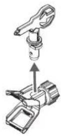
natural_image
Diagram of a circular component with radial grooves and a small threaded base, connected to a wire (no text or symbols)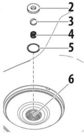
natural_image
Technical illustration showing mechanical assembly steps with no visible text or symbols
natural_image
Technical line drawing of a mechanical assembly with a drill bit inserted into a housing (no text or symbols)KORTSTONDIGE OPSLAG
natural_image
Illustration of a hand using a cable to lift a weight, next to a magnified view of a switch labeled 'I' (no text or symbols on the diagram itself)natural_image
Technical line drawing of a mechanical clamp or bracket assembly (no text or symbols)PROBLEEM OORZAAK OPLOSSING
https://go.wagner-group.com/hf-warranty-conditions

natural_image
Mechanical assembly diagram showing hands operating a tool with a spring (no text or symbols visible)natural_image
Technical line drawing of a mechanical device with hoses and components (no text or symbols)Spallaccio
natural_image
Mechanical assembly diagram showing two clamps inserted into a frame (no text or symbols)natural_image
Diagram of a mechanical device with a lever and rotary dial (no text or symbols)Preparare il colore
natural_image
Diagram showing a curved arrow pointing downward through a mechanical component (no text or symbols)SBLOCCAGGIO
DELL'AEROGRAFO
natural_image
Diagram of a car seatbelt mechanism with an arrow indicating clockwise motion (no text or symbols)natural_image
Technical line drawing of a car suspension system with attached components (no text or symbols)natural_image
Simple line drawing of a door with a circular button and a circular symbol with an arrow (no text or labels)
natural_image
Line drawing of a hand holding a spray gun (no text or symbols)natural_image
Simple line drawing of a door with a circular button and a rotation arrow (no text or symbols)natural_image
Line drawing of a mechanical component with attached clips (no text or symbols)Carica
natural_image
Mechanical assembly diagram showing a gear and shaft assembly with an arrow indicating direction (no text or symbols)Acceso a luce fissa
natural_image
Diagram showing a hand holding a door handle and a bottle inserted into a toilet (no text or symbols present)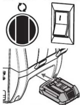
natural_image
Diagram of a medical procedure showing a catheter inserted into a patient's abdomen (no text or labels present)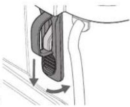
natural_image
Diagram of a hand holding a car hood with a curved handle and directional arrows indicating motion (no text or symbols)natural_image
Hand holding a spray gun over a circular object, no text or symbols visiblenatural_image
Two abstract diagrams: a circular symbol with a black rectangle and a rectangular box with a white circle, both without any text or symbols.natural_image
Technical line drawing of a mechanical device with two views showing assembly or assembly steps (no text or symbols present)natural_image
Hand holding a handheld device with wires, no visible text or symbolsnatural_image
Solid black rectangle with horizontal white stripes (no text or symbols)natural_image
Mechanical assembly diagram showing a lever mechanism with rotational motion indicated by arrows (no text or symbols present)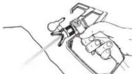
natural_image
Line drawing of a hand using a handheld device to interact with a device (no text or symbols present)natural_image
Mechanical assembly diagram showing a lever mechanism with rotational motion (no text or symbols)natural_image
Technical illustration of a mechanical device with a lever mechanism and a close-up view of the lever handle (no text or symbols present)natural_image
Line drawing of a handheld device with attached cable (no text or symbols)SVUOTAMENTO DEL TUBO FLESSIBILE DEL MATERIALE
natural_image
Two circular diagrams: one showing a curved arrow and the other a vertical bar with a circular arrow (no text or symbols)natural_image
Diagram showing a circular symbol with a switch and a rectangular box with internal markings (no text or symbols)natural_image
Line drawing of a mechanical tool with a screwdriver and lever (no text or symbols)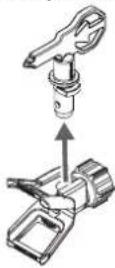
natural_image
Technical illustration showing mechanical assembly steps with no visible text or symbolsnatural_image
Technical line drawing of a mechanical assembly with a drill bit inserted into a housing (no text or symbols)natural_image
Three black-and-white diagrams showing a car interior, a circular switch, and a door with a handle (no text or symbols)natural_image
Illustration of a hand using a tool to lift a car, next to a close-up of a switch (no text or symbols present)5) Speqnere la pompa (OFF).
natural_image
Technical line drawing of a mechanical clamp or bracket assembly (no text or symbols)https://go.wagner-group.com/hf-warranty-conditions

GB Inspiration of a very special kind
Are you on the look-out for your next project? Then take a look at our project finder. Here, you'll find practical guides renovation, decoration and DIY. Make your home unique. Make it beautiful!

natural_image
Black-and-white photo of a woman sitting on a wicker chair by a wooden deck, with potted plants and a wooden fence in the background (no visible text or symbols)natural_image
Interior living room scene with a person seated in a chair, potted plant, and bookshelf (no visible text or symbols)natural_image
Black-and-white photo of a person pushing a wheelbarrow next to a wooden fence in a garden setting (no visible text or symbols)
natural_image
Interior scene of a child playing with a wooden play structure in a room, no visible text or symbolswagner-group.com/projects
GB More inspiration?
wagner-group.com/projects
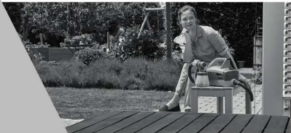
natural_image
Black-and-white photo of a person operating a power tool outdoors, surrounded by gardenery and a wooden deck (no visible text or symbols)natural_image
Black-and-white photo of a woman sitting on a wicker chair by a wooden deck, with potted plants and a glass coffee table nearby (no text or symbols visible)natural_image
Interior living room scene with a person seated in a chair, potted plant, and bookshelf (no visible text or symbols)F Repeignez votre terrasse !
NL Lak uw terras opnieuw!
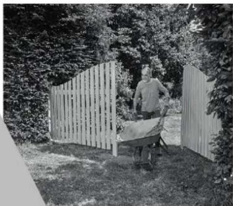
natural_image
Black-and-white photo of a person pushing a wheelbarrow next to a wooden fence in a garden setting (no text or symbols visible)
natural_image
Interior scene of a child playing on a wooden play structure in a room with framed artworks on the wall (no visible text or symbols)natural_image
Black-and-white photo of a woman sitting on a bench with a hairdryer and equipment, outdoors in a garden setting (no visible text or symbols)| D | J. WAGNER GMBHOtto-Lilienthal-Str. 1888677 MarkdorfT +49 0180 - 55 92 46 37hotline@wagner-group.com | SK | E-CORECO SK S.R.O.Královská ulica 8/7133927 01 ŠalaT +42 1948882850F +42 1313700077 | CZ | E-CORECO S.R.O.Na Roudné 102301 00 PlzeňT +42 734 792 823F +42 227 077 364 |
| F | J. WAGNER FRANCE SARLParc Work Center8 Route des Bois, Bâtiment CF-38500 Voiron - FranceT +33 (0)4 58 09 04 12 | GB | UK IMPORTERWAGNER SPRAYTECH (UK) LTDInnovation CentreSilverstone Park, SilverstoneNorthants NN12 8GXT +44 (0) 1327 368410 | DK | DVA A/SMarielundvej 48 C2730 HerlevT +45 70 234 239 |
| DK | ORKLA HOUSE CARE DANMARK A/SStationsvej 133550 SlangerupDanmarkT +45 47 33 74 00F +45 47 33 74 01 | NOR | ORKLA HOUSE CARE NORGE ASNedre Skøyen vei 26,PO Box 423, Skøyen0213 OsloT +47 22 54 40 19kunderservice.ohc@orkla.no | PL | PUT WAGNER SERVICEul. E. Imieli 2741-605 SwietochlowiceT +48/32/346 37 00F +48/32/346 37 13 |
| S | ORKLA HOUSE CARE ABBox 133564 23 BankerydSwedenT +46(0)36 37 63 00info@anza.se | ROM | ROMIB S.R.L.str. Poligonului nr. 5 - 7100070 Ploiesti ,judet PrahovaT +40-344801240office@romib.com.ro | CH | J. WAGNER AGIndustriestraße 229450 AltstättenT +41 71 - 7 57 22 11F +41 71 - 7 57 23 23 |
| E | MAKIMPORTHERRAMIENTAS, S.L.C/ Méjico n° 6Pol. El Descubrimiento28806 Alcalá de Henares (Madrid)T +34 902 199 021 /+34 91 879 72 00F +34 91 883 19 59 | AUS | WAGNER SPRAYTECHAUSTRALIA PTY. LTD.,8 – 10 Dansu CourtHallam, Victoria, 3803T +61 3 9587 2000F +61 3 9580 9120 | I | WAGNER SPAVia S. Vecchia 109,23868 Valmadrera (LC)Mobile +39 0341 210100wagner_it_va@wagner-group.com |


- CONTROL PRO 300 MOVE 18V
- Tragegurt
- Farbe vorbereiten
- Pistole entsichern
- Erdung
- ⚠️WARNUNG
- Trockenlauf
- VORSICHT
- Laden
- AUSLASSVENTIL ERSETZEN
- Translation of the original operating instructions
- Warning!
- Be safety-conscious !
- Congratulations for the purchase of your WAGNER Airless high pressure spray gun.
- Important! After each use, the equipment should be cleaned.
- General Safety Instructions
- Work area safety
- Electrical Safety
- Personal safety
- Power tool use and care
- Battery tool use and care
- Service
- Safety instructions for the charger and battery
- Health protection
- Flammable materials
- Explosion protection
- Danger of explosion and fire through sources of flame during spraying work
- Earthing the device
- Ventilation
- Secure device and spray gun
- Recoil of spray gun
- Max. operating pressure
- Coating substance
- High-pressure hose (safety note)
- Positioning device
- Maintenance and repairs
- Cleaning the unit
- Cleaning units with solvents
- Earthing of the object
- Usabel materials
- Unsuitable materials
- Field of application
- Information about the vibration level
- Controls and functions
- Operating modes
- Tools needed for assembly
- WARNING
- Hose
- Carrying strap
- Preparing the paint
- Select tip and gun filter
- Tip Size Paint Filter
- Locking and unlocking the gun
- Locking the gun
- Unlocking the gun
- Earthing
- Pressure relief procedure
- Dry running
- Refilling the container / bleeding the pump
- Charging
- Explanation of the indicator lights
- Indicator light
- Preparation of the Coating Material
- Make pump ready for operation
- Suck in material
- Practice
- CAUTION
- Spraying technique
- ADDITIONAL TIPS
- Unclogging the spray tip
- Do not use a needle or other sharp pointed instrument to clean the tip. The hard tungsten carbide can chip.
- If paint still will not spray from the spray tip, follow the steps on the next column.
- Unclogging the spray gun filter
- NEVER POKE THE FILTER WITH A SHARP INSTRUMENT!
- Unclogging the inlet filter
- Important cleaning notes
- READ THESE NOTES AND WARNINGS BEFORE YOU START TO CLEAN YOUR SPRAYER!
- Emptying the hopper
- Purging the paint hose
- You might need to add more cleaning solution to the hopper.
- Rinsing the hopper
- Make sure you do not drip any cleaning solution into the motor housing.
- Flushing the sprayer
- Cleaning the spray gun components
- IMPORTANT!
- Cleaning the inlet valve
- Replacing the outlet valve
- Replacing the pulsation damper
- SHORT-TERM STORAGE
- Shutdown
- Startup
- Preparing the sprayer for longterm storage
- Storage/Conservation of the gun
- Item Part # Description Quantity
- Accessories (not included in the delivery)
- + 1 year guarantee on this WAGNER DIY product
- Environmental protection
- Important Note regarding Product Liability!
- EU Declaration of conformity
- UKCA Declaration of conformity
- Sangle
- Mise à la terre
- Chargement
- Aspirer le produit
- AVERTISSEMENT
- Draagriem
- Verf voorbereiden
- Pistool vrijgeven
- Aarding
- Droogloop
- VOORZICHTIG
- Opladen
- Materiaal aanzuigen
- Verfslang leegmaken
- KORTSTONDIGE OPSLAG
- Spallaccio
- Preparare il colore
- SBLOCCAGGIO
- DELL'AEROGRAFO
- Carica
- SVUOTAMENTO DEL TUBO FLESSIBILE DEL MATERIALE
- GB Inspiration of a very special kind
Brand : WAGNER
Model : Control Pro 300 Move 18V
Category : Paint spray