R9259 - Indoor bike trainer HMS Premium - Free user manual and instructions
Find the device manual for free R9259 HMS Premium in PDF.

| Product Type | Indoor Bike Trainer |
| Brand | HMS Premium |
| Model | R9259 |
| Net Weight | 27.5 kg |
| Flywheel Weight | 9 kg |
| Dimensions (L x W x H) | 123-139 × 69.5 × 101.5 cm |
| Maximum Load | 120 kg |
| Power Supply | 2 AA batteries or 1 AAA battery (computer) |
| Resistance System | Magnetic brake, adjustable by knob |
| Display | LCD screen with TIME, SPEED, DISTANCE, CALORIES, HEART RATE functions |
| Heart Rate Sensors | Pulse sensors integrated in handlebars |
| Seat Adjustment | Height adjustable with locking button |
| Handlebar Adjustment | Fixed on vertical tube, not height adjustable |
| Pedal Type | Pedals with foot straps |
| Warranty | 24 months (Poland) |
| Maintenance | Clean with soft damp cloth, avoid harsh products |
| Safety | Free space 0.6 m, medical consultation recommended |
| Intended Use | Domestic, class H according to EN ISO 20957-1 |
| Extras | Padded backrest, front and rear stabilizers |
Frequently Asked Questions - R9259 HMS Premium
User questions about R9259 HMS Premium
0 question about this device. Answer the ones you know or ask your own.
Ask a new question about this device
Download the instructions for your Indoor bike trainer in PDF format for free! Find your manual R9259 - HMS Premium and take your electronic device back in hand. On this page are published all the documents necessary for the use of your device. R9259 by HMS Premium.
USER MANUAL R9259 HMS Premium
natural_image
Line drawing of a stationary exercise bike with adjustable arm and seat (no text or symbols)-
Manual instruction EN
-
Instrukcja obsługi PL
-
Návod k obsluze CZ
-
Manuel instruktion DA
-
Gebrauchsanweisung DE
-
Manual de instrucciones ES
-
Käsijuhend ET
-
Manuel d'instruction FR
-
Kézi utasítás HU
-
Manuale di istruzioni IT
-
Naudojimo instrukcijos LT
-
Rokasgrāmatas instrukcija LV
-
Handmatige instructie NL
-
Manual de instruções PT
-
Instructiuni manuale RO
-
Návod na obsluhu SK
-
Navodila za uporabo SL
-
Instruktionsbok SV
-
Інструкція з експлуатації UK

text_image
Technical diagram of a mechanical device with numbered components and labeled parts, including gears and control panels.


text_image
Technical diagram of a mechanical device with numbered components and labeled parts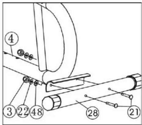
text_image
Technical diagram of a mechanical assembly with numbered components and labeled parts- A
text_image
METALOWY WSPORNIK PRZEWÓD OPORU PRZEWÓD DOLNYB
text_image
PRZEWÓD OPORU PRZEWÓD DOLNYC
text_image
PRZEWÓD OPORU PRZEWÓD DOLNYD
text_image
27 46 41 28 41 46 13 12 1- & 5.
text_image
Technical diagram of a mechanical device with numbered components for identification
text_image
Technical diagram of a mechanical assembly with numbered components, likely for engineering or manufacturing documentation.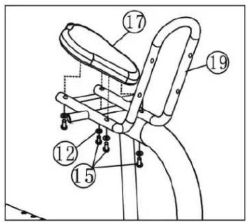
text_image
Technical diagram of a bicycle seat assembly with numbered components for identification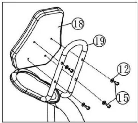
text_image
Technical diagram of a mechanical device with numbered components and alignment lines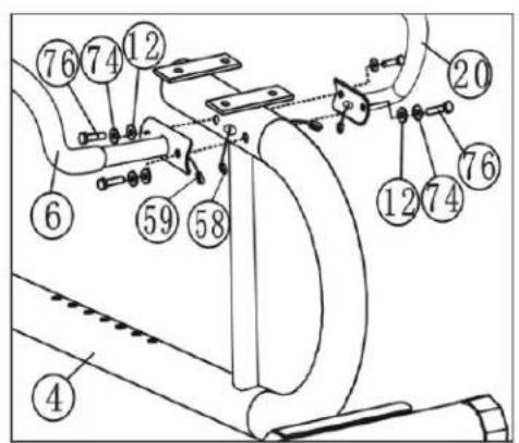
text_image
Technical diagram of a mechanical assembly with numbered components for identification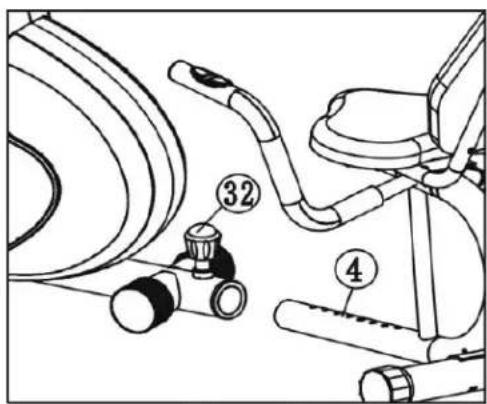
text_image
Technical diagram of a stationary exercise chair with labeled parts including seat 32 and base 4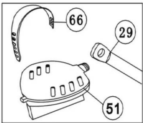
text_image
66 29 51| No | Description | Quantity | No | Description | Quantity |
| 1 | Plastic rear base cover | 2 | 40 | Cable clamp | 1 |
| 2 | Anti-slip pad | 2 | 41 | M5x70 screw | 1 |
| 3 | M10 cap | 4 | 42 | M6 nut | 3 |
| 4 | Seat adjustment post | 1 | 43 | M6x50 screw | 1 |
| 5 | Tenant | 1 | 44 | M10x65 screw | 1 |
| 6 | Left part of the steering wheel | 1 | 45 | M8x40 screw | 1 |
| 7 | Foam handle | 2 | 46 | Front vertical tube | 1 |
| 8 | Centre part of the steering wheel | 1 | 47 | Magnetic spring | 1 |
| 9 | Round plug Φ25 | 4 | 48 | Washer Φ10 | 4 |
| 10 | Bush for the centre part of the steering wheel | 2 | 49 | Rotating plastic cover | 4 |
| 11 | Plastic cover | 1 | 50 | Voltage control cable | 1 |
| 12 | Arc washer Φ8 | 18 | 51 | P&L pedals | 2 |
| 13 | Washer Φ8 | 7 | 52 | Voltage control | 1 |
| 14 | M8x20 screw | 6 | 53 | Pressure wheel bracket | 1 |
| 15 | M8x40 screw | 8 | 54 | M5x35 Phillips screw | 1 |
| 16 | M8 nut | 6 | 55 | Pressure wheel | 1 |
| 17 | Saddle | 1 | 56 | Sensor cable | 1 |
| 18 | Backrest | 1 | 57 | Computer | 1 |
| 19 | Saddle frame | 1 | 58 | Heart rate cable 1 | 1 |
| 20 | Right side of the steering wheel | 1 | 59 | Pulse cable 2 | 2 |
| 21 | M10x70 screw | 4 | 60 | Pulse measurement sensor | 2 |
| 22 | Washer Φ10 | 4 | 61 | Cap | 1 |
| 23 | Right and left cover | 2 | 62 | Plug | 4 |
| 24 | 4V belt | 1 | 63 | Bracket | 1 |
| 25 | Main belt wheel | 1 | 64 | Front cover | 1 |
| 26 | Bearing set | 1 set | 65 | Plastic crank cover | 2 |
| 27 | Front stabiliser | 1 | 66 | Pedal strap | 2 |
| 28 | Rear stabiliser | 1 | 67 | Washer Φ5 | 1 |
| 29 | Crank axle | 1 | 68 | Washer Φ4 | 1 |
| 30 | Main frame | 1 | 69 | Self-locking cross-head screw ST4.2x20 | 9 |
| 31 | Cross-head screw | 1 | 70 | Self-locking cross-head screw ST4x10 | 1 |
| 32 | Knob | 1 | 71 | Cross screw | 1 |
| 33 | Bushing | 1 | 72 | Rim | 1 |
| 34 | M5 nut | 1 | 73 | ST2.2x10 self-locking cross-head screw | 1 |
| 35 | M10x1x5 nut | 4 | 74 | Spring washer Φ8 | 10 |
| 36 | M10x1x3 nut | 1 | 75 | M8x16 screw | 4 |
| 37 | Flywheel | 1 | 76 | M8x20 screw | 4 |
| 38 | Spacer | 1 | 77 | Key | 1 |
| 39 | Screw | 2 | 78 | Screwdriver | 1 |
SAFETY NOTES
This product is intended for domestic use only and has been designed to ensure optimum safety. Please observe the following rules:
- Medical consultation – consult your doctor before starting training, especially if you are taking medication that affects your heart, blood pressure or cholesterol levels. A mandatory consultation is also required for people over 35 years of age and those with health problems.
- Warm-up – always warm up before starting exercise.
- Response to symptoms – in the event of pain, dizziness, chest pain, irregular heartbeat or other worrying symptoms, stop training immediately and consult a doctor. Injuries may result from incorrect or overly intense training.
- Securing the equipment – during and after exercise, secure the device against access by children and animals.
- Positioning the equipment – the equipment should be placed on a dry, stable and level surface. Remove sharp objects from the surrounding area, protect against moisture and use a non-slip mat.
-
Free space – ensure a minimum of 0.6 m of free space around the equipment, including space for emergency descent.
-
Connection inspection – before first use and regularly check the fastening of screws, bolts and other connections.
- Device efficiency – before each workout, ensure that all parts are properly secured and that the device is fully functional.
- Wear and damage – regularly check the technical condition, especially the foam handles, leg caps and upholstery. Damaged parts must be replaced immediately.
- Structural safety – do not insert any objects into the openings of the device.
- Protruding parts – pay attention to protruding adjusters and other structural parts that may interfere with your workout.
- Intended use – use the equipment for its intended purpose. In the event of damage or disturbing noises, stop training and do not use the device until the problem has been rectified.
- Sportswear – exercise in comfortable clothing and sports footwear. Avoid loose clothing that could get caught on the equipment.
- Equipment class – the device belongs to class H according to EN ISO 20957-1 and is intended for home use only. It is not suitable for therapeutic, rehabilitation or commercial use.
- Lifting and carrying - maintain correct posture to avoid spinal injuries.
- Accessibility for children – this product is intended for adults only. Children should not have access to the device without supervision.
- Assembly – assemble the device according to the instructions, using only the parts included in the set. Check that all parts are present before assembly.
Warning: Read the instructions before using the fitness equipment. The manufacturer is not liable for injuries or damage resulting from improper use.
Technical data
• Net weight: 27.5 kg
• Flywheel: 9 kg
• Dimensions when unfolded: 123-139 × 69.5 × 101.5 cm
• Maximum load: 120 kg
Maintenance
• Clean the device with a soft, damp cloth.
• Do not use aggressive cleaning agents.
- Remove sweat marks – their acidic reaction may damage the coating.
• Store the equipment in a dry place, protecting it from moisture and corrosion.
Resistance adjustment and braking
- Resistance is adjusted using the knob under the handlebars: turn it to the left (−) to decrease resistance, to the right (+) to increase it.
• To stop the device, simply stop pedalling – there is no locking system or safety brake.

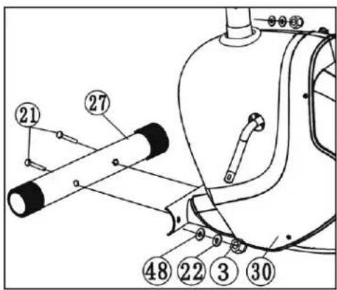
ASSEMBLY
1. Front stabiliser assembly
Attach the front stabiliser (27) to the main frame (30) using two bolts (21), washers (48 and 22) and nuts (3).
2. Rear stabiliser assembly
Attach the rear stabiliser (28) to the seat adjustment tube (4) using bolts (21), washers (48 and 22) and nuts (3).
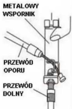
3. Handlebar stem assembly
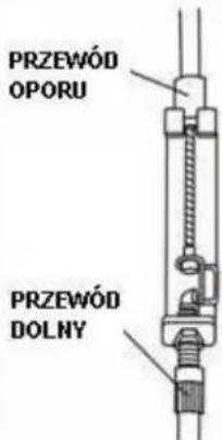
• Pull the end of the resistance cable (56) through the resistance adjustment cable hook, as shown in Figure A.
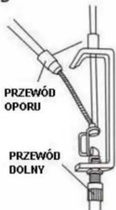
- Pull the tension control cable (52) through the hole in the metal tension control cable bracket (50) as shown in Figure B.
- Connect the voltage control cable (52) to the resistance adjustment cable (50) — as shown in Figure C.
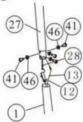
- Connect the pulse cables and sensor to the cables located in the steering column.
- Insert the front steering column (46) into the main frame (30) and secure it with four screws (14) with washers (74 and 12) as shown in Figure D.
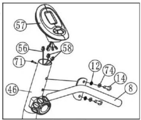
4. Computer installation
Connect the computer cable (56) and pulse cables (58) to the cables coming out of the computer. Attach the computer to the front vertical tube (46), make sure it fits snugly, and tighten it with a screw (71).
5. Assembling the small front handlebar
Connect the steering wheel (8) to the steering column (46) using the set of screws (14), washers (74) and (12).
6. Saddle assembly
Connect the saddle frame (19) to the saddle adjustment post (4) using eight screws (75), washers (13) and nuts (16).
7. Saddle and backrest assembly and adjustment
Attach the saddle (17) and backrest (18) to the frame (19) using eight sets of screws (15) and washers (12).
8. Assembling the left and right handlebars
- Connect pulse cable II (59) to the left and right parts of the handlebar (6, 20) and to pulse cable I (58) coming out of the seat adjustment frame (4).
- Secure both parts of the handlebar (6, 20) to the saddle adjustment frame (4) using four screws (76) and washers (74 and 12).
- Pull the knob (32), insert the saddle frame (4) into the main frame (30), align it with the appropriate hole, set the desired position and tighten the knob (32).
9. Pedal assembly
- Connect the straps (66) to the right and left pedals (51).
• Then attach the pedals (51) to the crank (29).
Note: The left and right pedals and cranks are marked with the letters "L" (left) and "R" (right).
COMPUTER
• MODE/SELECT – function selection
- SET – settings (if available)
- RESET/CLEAR – reset values (if available)
• AUTO ON/OFF – automatic switch-on/off after 4 minutes of inactivity
WARNING! Heart rate monitoring systems may be inaccurate. Excessive exercise can lead to serious injury or death. If you feel unwell, stop exercising immediately.
Measurement functions:
• TIME (TMR) – exercise time
• SPEED (SPD) – current speed
• DISTANCE (DST) – distance travelled
• CALORIES (CAL) – calories burned
• PULSE – heart rate measurement (hands on sensors)
Power supply: 2 AA batteries or 1 AAA battery. Replacement taking longer than 15 seconds will result in data loss.
Possible faults and how to resolve them
| Fault | Cause | Solution |
| The base is unstable | Uneven floor or a small object under the stabiliser.The front and rear stabilisers were not levelled during installation. | Remove the object from under the stabiliser.Tighten the front and rear stabilisers. |
| The steering column is not stable | Loose bolts. | Tighten all screws securing the steering column. |
| Disturbing noises from moving parts | Incorrectly tightened components. | Remove the cover and check the mechanical connections. |
| No resistance during exercise | Increased gap between magnetic resistance wires.Damaged resistance regulator.The resistance belt has slipped. | Remove the cover and check the cables.Replace the resistance regulator.Check and adjust the belt. |
Training instructions
- Warm-up - at least 30 seconds for each exercise reduces the risk of injury.
- Position – sit upright, feet in the pedal straps, hands on the handlebars.
- Training – follow the recommendations, consult your doctor if you are not physically active.
- Organisation – warm up for 5–10 minutes, finish with stretching and gradually reduce the intensity.
EN: The marking of the equipment with the crossed-out waste container symbol indicates that it is prohibited to place used electrical and electronic equipment with other waste. According to the WEEE Directive on the management of used electrical and electronic waste, separate disposal methods must be used for this type of equipment.
The user who intends to dispose of this product is obliged to take it to a collection point for used electrical and electronic equipment, thus contributing to reuse, recycling or recovery and thus to the protection of the environment. To do this, please contact the point from which the appliance was purchased or your local authority. Hazardous components contained in electronic equipment may cause long-term adverse effects on the environment, as well as harmful effects on human health.
- The Seller, on behalf of the Guarantor, provides a guarantee in the territory of the Republic of Poland for a period of 24 months from the date of sale.
-
The guarantee will be honoured by the shop or service centre upon presentation by the customer:
-
a legibly and correctly completed warranty card with the sales stamp and the seller's signature,
- a valid proof of purchase of the equipment with the date of sale / receipt, the goods claimed.
- Any defects and damage discovered during the warranty period will be repaired free of charge within a maximum of 21 days from the date of delivery of the goods to the service.
- In the case of the necessity to import parts, the repair period may be extended by the time necessary for their import, but not longer than 90 days.
-
The warranty does not cover:
-
mechanical damage and defects caused by them,
- damages and defects resulting from improper use and storage,
- improper assembly and maintenance,
-
damage and wear of components such as cables, straps, rubber parts, pedals, sponge grips, wheels, bearings, etc.
-
The warranty is void in the event of:
- expiry date,
- self-repair,
- failure to observe the rules of correct operation.
- Product returned for repair should be complete and clean. In the case of defects the service has the right to refuse acceptance for repair. If the product is delivered dirty, the service centre may refuse to accept it or clean it at the customer's expense with his written consent.
- The warranty does not cover installation and maintenance work, which, according to the user manual, must be carried out by the user himself.
- The guarantor also informs that it provides post-warranty service.
- The goods should be protected for shipping.
- In order to make use of the warranty, please follow the procedure on the website: https://serwis.abisal.pl/.
In case of non-conformity of the sold thing with the contract, the buyer is entitled by law to legal remedies from and at the expense of the seller. The guarantee does not affect such remedies.
THE EQUIPMENT IS NOT INTENDED FOR REHABILITATION AND THERAPY
NOTES ON THE COURSE OF REPAIRS
| Item | Date of notification | Date of provision | Course of repairs | Signature of the recipient (shop, owner) |
KARTA GWARANCYJNA
CONDITIONS DE GARANTIE:
text_image
QR code image containing encoded data, no visible human-readable textHMS-FITNESS.COM

HMS®
IMPORTER: ABISAL SP. Z O.O., ul. Pyskowicka 17, 41-807 Zabrze, Polska
DISTRIBUTOR: ABISTORE SPORT S.R.O, U Cihelny 230/3, 74801 Hlučín, Česká Republika