2100Delta - Measuring equipment Beha-Amprobe - Free user manual and instructions
Find the device manual for free 2100Delta Beha-Amprobe in PDF.
| Product type | TRMS two-pole voltage tester with clamp ammeter |
| Brand | Beha-Amprobe |
| Model | 2100Delta |
| Dimensions | 210 x 63 x 37 mm |
| Weight | 275 g |
| Power supply | 2 LR03 (AAA) 1.5 V alkaline batteries |
| Battery life | More than 10,000 measurements |
| AC voltage range | 1 V to 1000 V (15...800 Hz) |
| DC voltage range | 1 V to 1500 V |
| AC current range (TRMS) | 0.1 A to 200 A |
| Continuity test | 0...500 kΩ |
| Resistance test | 0...100 kΩ |
| Diode test | Yes |
| Phase rotation test | 170...1000 V AC (40...70 Hz) |
| Cable break detector | 100...1000 V AC (50/60 Hz) |
| Overvoltage category | CAT IV 600 V / CAT III 1000 V |
| Protection rating | IP64 |
| Operating temperature | -15 °C to +55 °C |
| Warranty | 4 years |
| Maintenance | Cleaning with a damp cloth and mild detergent |
Frequently Asked Questions - 2100Delta Beha-Amprobe
User questions about 2100Delta Beha-Amprobe
0 question about this device. Answer the ones you know or ask your own.
Ask a new question about this device
Download the instructions for your Measuring equipment in PDF format for free! Find your manual 2100Delta - Beha-Amprobe and take your electronic device back in hand. On this page are published all the documents necessary for the use of your device. 2100Delta by Beha-Amprobe.
USER MANUAL 2100Delta Beha-Amprobe
2100-Delta Voltage Tester with Current-Function TRMS
User Manual
English
Limited Warranty and Limitation of Liability
Your Beha-Amprobe product will be free from defects in material and workmanship for 4 years from the date of purchase unless local laws require otherwise. This warranty does not cover fuses, disposable batteries or damage from accident, neglect, misuse, alteration, contamination, or abnormal conditions of operation or handling. Resellers are not authorized to extend any other warranty on the behalf of Beha-Amprobe. To obtain service during the warranty period, return the product with proof of purchase to an authorized Beha-Amprobe Service Center or to an Beha-Amprobe dealer or distributor. See Repair Section for details. THIS WARRANTY IS YOUR ONLY REMEDY. ALL OTHER WARRANTIES - WHETHER EXPRESS, IMPLIED OR STATUTORY - INCLUDING IMPLIED WARRANTIES OF FITNESS FOR A PARTICULAR PURPOSE OR MERCHANTABILITY, ARE HEREBY DISCLAIMED. MANUFACTURER SHALL NOT BE LIABLE FOR ANY SPECIAL, INDIRECT, INCIDENTAL OR CONSEQUENTIAL DAMAGES OR LOSSES, ARISING FROM ANY CAUSE OR THEORY. Since some states or countries do not allow the exclusion or limitation of an implied warranty or of incidental or consequential damages, this limitation of liability may not apply to you.
Repair
All Beha-Amprobe tools returned for warranty or non-warranty repair or for calibration should be accompanied by the following: your name, company's name, address, telephone number, and proof of purchase. Additionally, please include a brief description of the problem or the service requested and include the test leads with the product. Non-warranty repair or replacement charges should be remitted in the form of a check, a money order, credit card with expiration date, or a purchase order made payable to Beha-Amprobe.
In-warranty Repairs and Replacement – All Countries
Please read the warranty statement and check your battery before requesting repair. During the warranty period, any defective test tool can be returned to your Beha-Amprobe distributor for an exchange for the same or like product. Please check the "Where to Buy" section on beha-amprobe.com for a list of distributors near you. Additionally, in the United States and Canada, in-warranty repair and replacement units can also be sent to an Amprobe Service Center (see address below).
Non-warranty Repairs and Replacement – Europe
European non-warranty units can be replaced by your Beha-Amprobe distributor for a nominal charge. Please check the "Where to Buy" section on beha-amprobe.com for a list of distributors near you.
Beha-Amprobe
Division and reg. trademark of Fluke Corp. (USA)
USA: Canada:
Amprobe Everett, WA 98203 Mississauga, ON L4Z 1X9 Tel: 877-AMPROBE (267-7623) Tel: 905-890-7600
Non-warranty Repairs and Replacement - Europe
European non-warranty units can be replaced by your Amprobe distributor for a nominal charge. Please check the "Where to Buy" section on beha-amprobe.com for a list of distributors near you.
Beha-Amprobe
Division and reg. trademark of Fluke Corp. (USA)
Germany\* United Kingdom
In den Engematten 14 52 Hurricane Way
79286 Glottertal Norwich, Norfolk
Germany NR6 6JB United Kingdom
Phone: +49 (0) 7684 8009 - 0 Phone: +44 (0) 1603 25 6662
The Netherlands - Headquarters\*\*
Science Park Eindhoven 5110
5692 EC Son
The Netherlands
Phone: +31 (0) 40 267 51 00
beha-amprobe.com
*(Correspondence only – no repair or replacement available from this address. European customers please contact your distributor.) **single contact address in EEA Fluke Europe BV
CONTENTS
SYMBOLS....3
SAFETY INFORMATION ....3
UNPACKING AND INSPECTION ....4
FEATURES....4
Safety Instructions ....5
Before Using the Tester....6
Switching ON / OFF the Tester / Auto Power OFF ......6
Voltage Test (Two Pole) (V) TRMS....7
Single-Pole Phase Test....7
Continuity Test (Rx)....7
Determining the Phase Rotation Indication....7
Current Measurement (A) TRMS....8
Resistance Measurement (Ω)......8
Non Contact Cable Break Detector / EF (Electric Field) 8
Voltage Mode "<10V": 1V...1000VAC/1500VDC.....8
Frequency Measurement (Hz)....9
Low Resistance Indication (L Rx)....9
Diode Test (◀)....9
Data Hold (HOLD) 9
Measurement Area Illumination / Flashlight / LCD Backlight ....9
Test Probe Attachment to Main Body....10
Test Probe Storage on Back Side 10
Test Probe Protection Cover....10
How to Use "Opener-Tool" to Open UK Safety Sockets....11
How to Use Storage Area for "Gs 38 Protective Probe Cap"....11
How to Use Storage Area for "4mm ∅ Test Probe Extension"....11
SPECIFICATIONS....12
MAINTENANCE AND REPAIR....13
BATTERY REPLACEMENT....14
text_image
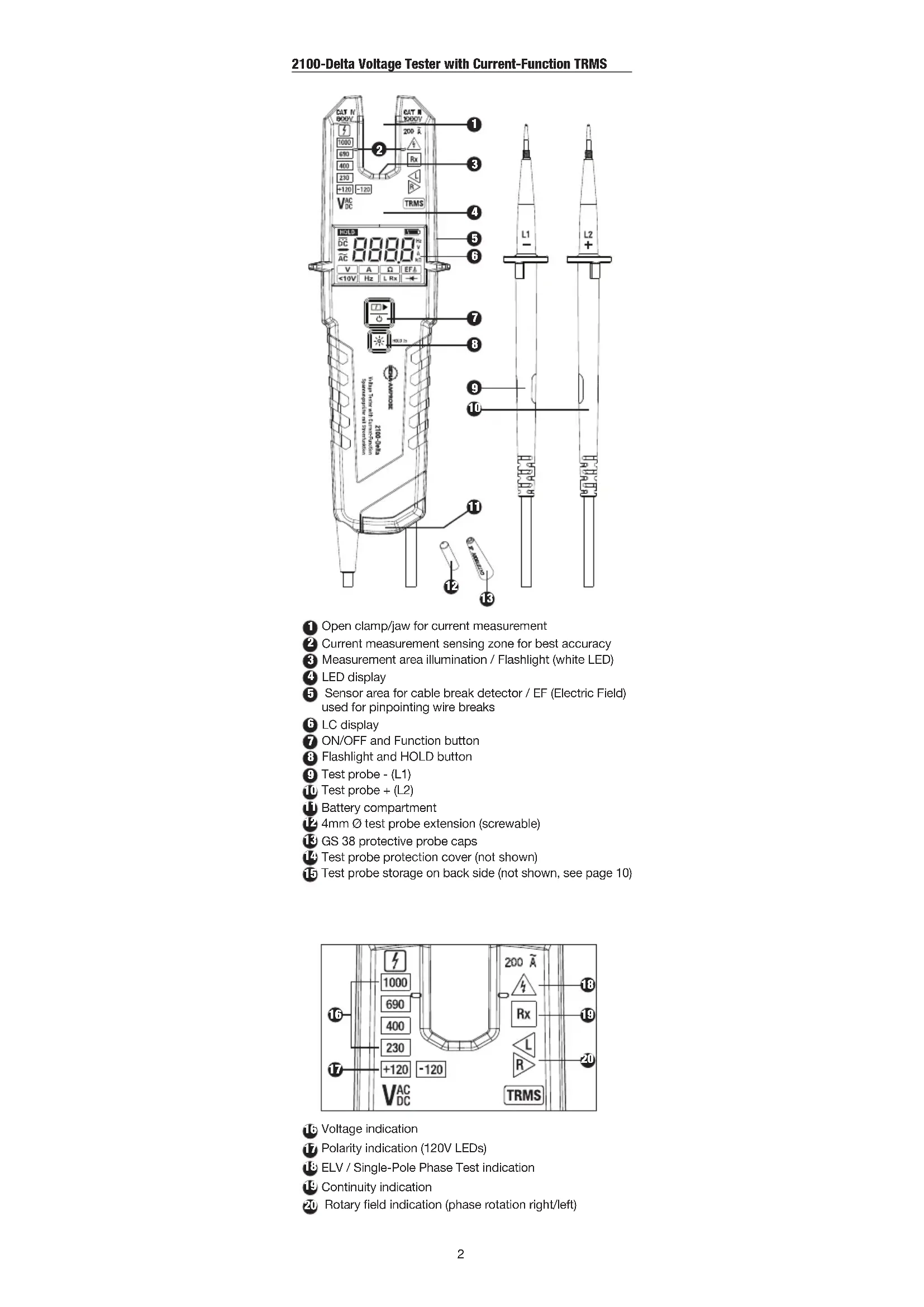
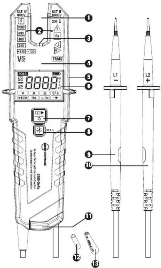
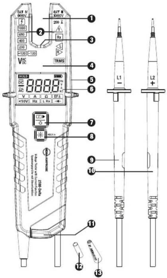
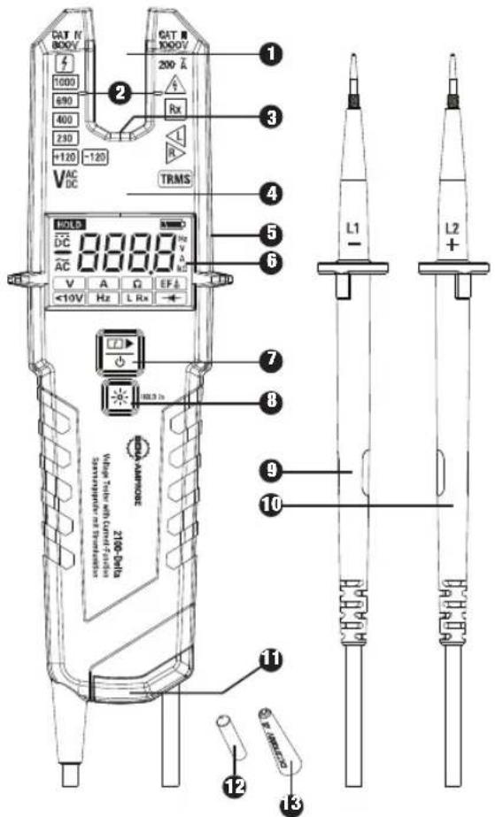
CAT N 800V 1000 690 400 230 +120 -120 VAC DC CAT N 1000V 200 Λ Rx TRMS 1 3 4 5 6 7 8 L1 - L2 + V A Ω EFA V <10V Hz L Rx +10V - HOLD TO AMPORCE ZIG-GEFE White laser white laser Temperature reading Temperature reading 11 12 13① Open clamp/jaw for current measurement
② Current measurement sensing zone for best accuracy
③ Measurement area illumination / Flashlight (white LED)
4 LED display
5 Sensor area for cable break detector / EF (Electric Field) used for pinpointing wire breaks
6 LC display
7 ON/OFF and Function button
8 Flashlight and HOLD button
9 Test probe - (L1)
10 Test probe + (L2)
Battery compartment
12 4mm ∅ test probe extension (screwable)
13 GS 38 protective probe caps
14 Test probe protection cover (not shown)
15 Test probe storage on back side (not shown, see page 10)
text_image
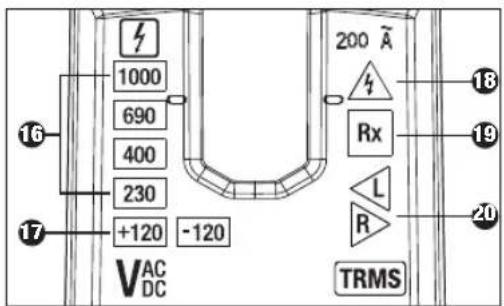
1000 690 400 230 +120 -120 VAC DC 200 A Rx L R TRMS 18 19 20 1716 Voltage indication
Polarity indication (120V LEDs)
18 ELV / Single-Pole Phase Test indication
19 Continuity indication
20 Rotary field indication (phase rotation right/left)
text_image
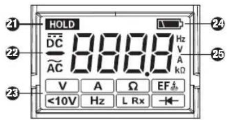
HOLD DC AC 888.8 Hz V A Ω EF <10V Hz L Rx21 Data HOLD indicator
22 AC/ DC and polarity indicators
23 Function symbols from left to right,
upper row: - voltage test (measurement) "V" + continuity "Rx"
- current measurement "A"
- resistance measurement "Ω"
- cable break detection "EF
lower row: - voltage mode „<10V"
- frequency measurement "Hz"
- low resistance indication "L Rx"
- diode test "
24 Low battery indication
25 Four digit - seven segment display
SYMBOLS
| Caution! Risk of electric shock. | |
| Caution! Refer to the explanation in this manual. | |
| Application of current sensor to and removal from UNINSULATED HAZARDOUS LIVE conductors is permitted. | |
| The equipment is protected by double insulation or reinforced insulation. | |
| Equipment for working under live voltage | |
| CE | Complies with European Directives. |
| This product complies with the WEEE Directive marking requirements. The affixed label indicates that you must not discard this electrical/electronic product in domestic household waste. Product Category: With reference to the equipment types in the WEEE Directive Annex I, this product is classed as category 9 “Monitoring and Control Instrumentation” product. Do not dispose of this product as unsorted municipal waste. | |
| Battery |
SAFETY INFORMATION
The two pole voltage tester and test probes complies with: IEC 61243-3:2014, EN 61243-3:2014, DIN VDE 0682-401:2015
Dust/water ingress protection IP64 per EN 60529
Electromagnetic Compatibility (EMC): IEC 61326-1
The current measurement function (open jaw) on this tester complies with IEC/EN 61010-1 and IEC/EN 61010-2-032
Measurement Category III is applicable to test and measuring circuits connected to the distribution part of the building's low-voltage MAINS installation.
Measurement Category IV is applicable to test and measuring circuits connected at the source of the building's low-voltage MAINS installation.
For Use by Competent Persons
Anyone using this voltage tester should be knowledgeable and trained about the risks involved with measuring voltage and current, especially in an industrial setting, the importance of taking safety precautions and of testing the voltage tester before and after using it to ensure that it is in good working condition.
Depending on the internal impedance of the voltage tester there will be a different capability of indicating the presence or absence of operating voltage in case of the presence of interference voltage.
A voltage tester of relatively low internal impedance, compared to the reference value of 100 kΩ, will not indicate all interference voltages having an original voltage value above the ELV level. When in contact with the parts to be tested, the voltage tester may discharge temporarily the interference voltage to a level below the ELV, but it will be back to the original value when the voltage tester is removed.
When the indication "voltage present" does not appear, it is highly recommended installing earthing equipment before work.
A voltage tester of relatively high internal impedance, compared to the reference value of 100 kΩ, may not permit to clearly indicate the absence of operating voltage in case of presence of interference voltage.
When the indication "voltage present" appears on a part that is expected to be disconnected of the installation, it is highly recommended confirming by another means (e.g. use of an adequate voltage tester, visual check of the disconnecting point of the electric circuit, etc.) that there is no operating voltage on the part to be tested and to conclude that the voltage indicated by the voltage tester is an interference voltage.
A voltage tester declaring two values of internal impedance has passed a performance test of managing interference voltages and is (within technical limits) able to distinguish operating voltage from interference voltage and has a means to directly or indirectly indicate which type of voltage is present.
⚠️ Warning: Read Before Using
To avoid possible electric shock or personal injury:
- The operating instructions contain information and references required for safe operation and use of the voltage tester. Before using the voltage tester, read the operating instructions carefully and follow them in all respects.
- Failure to follow the instructions or to comply with warnings and references may result in hazard to the user and damage to the voltage tester.
- If the voltage tester is used in a manner not specified by the manufacturer, protection provided by the voltage tester may be impaired.
- Comply with local and national safety requirements.
- Use proper protective equipment as required by local or national authorities.
UNPACKING AND INSPECTION
Your shipping carton should include:
1 2100-Delta Voltage Tester with Current-Function
1 Holster
2 GS 38 protective probe caps
2 4mm ∅ test probe extension (screwable)
2 1.5V alkaline batteries, IEC LR03 (installed)
1 User manual
If any of these items are damaged or missing, return the complete package to the place of purchase for an exchange.
FEATURES
The Beha-Amprobe 2100-Delta is a rugged and easy-to-use two pole voltage tester for voltage, continuity and current checks. The 2100-Delta is for electricians in residential, industrial, and commercial applications for use in a wide voltage range and safety rating are built according to latest voltage tester standard EN 61243-3:2014 and are GS approved.
- AC and DC voltage test with LED and LC display.
- Voltage range: 1 to 1000 V AC (15...800 Hz) and 1 to 1500 V DC(±)
- Safety rating (overvoltage category): CAT IV / 600 V, CAT III / 1000 V
• Automatic AC/DC voltage detection, indication of polarity
• Vibration motor in addition to voltage indication - Open clamp meter for current measurement up to 200 A
-
Two pole phase rotation indication – no third hand required. Separate indicators for "Right" and "Left" rotation.
-
Resistance measurement, Continuity test, low resistance indication (<20Ω) and diode test
• Non contact cable break detector / EF (electric field)
• Frequency measurement
• Single pole test for phase indication
• Data Hold (HOLD)
• LCD Backlight and Flashlight for dark environments
• IP 64 splash-proof and dust-tight
The voltage testers has been designated and tested in accordance with the safety regulations for voltage testers when leaving the factory. To prevent injuries and damages to the user and the voltage tester, follow the safety instructions in this manual.
⚠️⚠️ Read Before Using:
Danger of electric shock.
- Read all safety information before you use the Product. Carefully read all instructions.
- Examine the case before you use the Product. Look for cracks or missing plastic. Do not use the Product if it is damaged.
- Do not use the Product if it operates incorrectly.
- Tester must be operated by trained users only.
- To avoid an electric shock, observe the precautions when working with voltages exceeding 120 V (60 V) DC or 50 V (25 V) r.m.s. AC. In accordance with general safety regulations these values represent the maximum allowed limits for contact voltages (values in brackets refer to limited ranges, e.g. in medical areas).
- The acoustic indication ≥50 V AC and ≥120 V DC is only to warn the user, not for measuring.
- Before using the voltage tester at locations with a high background noise level, it should be determined whether the audio signal is perceptible.
- The voltage tester shall not be used with the battery compartment open.
- Before using the voltage tester, ensure that the test lead and voltage tester are in perfect working condition. Look out for broken cables or leaking batteries (if applicable).
- The batteries shall be checked before use and replaced if necessary.
- Hold the voltage tester and accessories by the designated grip areas and probe handle areas only, the LCD screen and LED indicator must not be covered. Do not touch the test probes in any case before and during test.
- The voltage tester may be used only within the specified measurement ranges and in low-voltage installations up to 1000V AC and 1500V DC.
- The voltage tester may be used only in the overvoltage category for which it has been designed for!
- Before and after use, always check that the voltage tester is in perfect working condition (e.g. check on a known voltage source or on a proving unit).
- The functioning of the voltage tester shall be checked shortly before and after a test. If indication of one or more function fails, or not functioning at all is indicated, the voltage tester must be taken out of operation immediately.
- The voltage tester complies with protection degree IP 64 (splash-proof and dust-tight) and therefore can also be used under humid conditions.
- It is not permitted to use the tester during rain or precipitation.
- Never use the tester in explosive environment.
- The voltage tester operates correctly only within a temperature range of -15^ to +55^ at relative air humidity less than 85% (without condensation).
- If the safety of the user cannot be guaranteed, the voltage tester must be taken out of operation and secured against unintentional use.
- Safety is no longer guaranteed in the following cases:
- Obvious damage
- If the voltage tester can no longer perform the required measurements/tests
- Stored for too long in unfavorable conditions
- Damaged during transport
-
Leaking batteries
-
For all work, observe the accident prevention regulations of the professional trade association for electrical installations and equipment and/or other local safety regulations.
- Unauthorized persons shall not disassemble or assemble the voltage tester and supplementary equipment. The voltage tester may be serviced by an Beha-Amprobe authorized service technician only.
- Operational safety is no longer guaranteed if the voltage tester is modified or altered.
- The current test can also be performed on single insulated wires and uninsulated conductors or busbars. In the case of non double insulated wires, it is necessary to pay outmost attention not to touch the wire and keep distance to avoid electric shock.
- Use only specified replacement parts.
- Remove batteries to prevent battery leakage and damage to the Product if it is not used for an extended period.
Before Using the Tester
⚠️ Before conducting any test, follow the safety instructions. Before using the voltage tester, always perform a function test.
⚠️ Disconnect the voltage tester completely from any measuring circuit first.
The "GS 38 protective cap" can be removed before the tests. To do this, pull them forward off the test probes.
The "GS 38 protective cap" may be required by national regulations or directives.
Switching ON / OFF the Tester / Auto Power OFF
Auto-Power-ON/ switching ON
The tester switches on automatically when it detects shorten test probes (continuity), or an AC or DC voltage above approx. 6 V or a live phase on L2+ probe (single pole phase test).
Alternatively, the tester can be switched on by pressing ON/OFF button 7 or "Flashlight/HOLD" button 8.
Auto-Power OFF / switching OFF
Tester is automatically powered OFF after approx. 30 sec when there is no signal contacted to the test probes. The flashlight automatically switches OFF after approx. 30 sec. Alternatively, the tester can be switched OFF by pressing the ON/OFF button for 5 sec.
Function Test/Self-Test:
Switch ON voltage tester by shorting the test probes, while unit is OFF. All LEDs, flashlight, buzzer, vibration, all symbols on LCD and backlight shall be on for approx. two seconds Note: Self test will be also performed automatically after battery replacement.
If the Low Battery symbol blinks after the self test is performed, the batteries must be changed.
Before and after use, always test the voltage tester on a known voltage source or on a proving unit.
⚠ The voltage tester must be no longer used if one or more functions fail or if no functionality is indicated.
⚠️ Remove discharged batteries immediately from the voltage tester to prevent any leaks.
The ELV LED 18 functions even without batteries at voltages > 50 VAC / 120 VDC.
⚠️ CAUTION: All other indications will not work without batteries or discharged batteries.
Voltage Test (Two Pole) (V) TRMS
⚠️ ⚠️ Follow the safety instructions. Connect both test probes to the test object.
- The 2100-Delta switches ON automatically when voltage exceeds approx. 6V and can measure voltages in range of 6V-1000VAC/1500VDC. The voltage measurement is shown on the LC display and the voltage level is also indicated by LEDs if it is above 120 V
- The buzzer and vibration function turn on if the voltage is higher than 50 V AC or 120 V DC.
- Voltage polarity is indicated in the following way on LCD: AC: AC symbol is on +DC: DC symbol is on -DC: - symbol and DC symbol is on
- Above 120 V, the polarity is shown in addition on the LED display in the following way. AC: both 120 V LEDs are on +DC: left +120 V LED is on -DC: right -120 V LED is on
The “L2 +” probe should be connected to positive (+) potential, and the tester LED Polarity indication will show the “+DC” symbol. When the “L2 +” probe is connected to negative potential (-) the tester will indicate “-DC” polarity. During voltage test, L or R LED/Symbol may light up. In case of discharged batteries, only the ELV LED lights up when voltage above 50 VAC / 120 VDC is detected.
Single-Pole Phase Test
The single-pole phase test works with an AC voltage exceeding approx. 100 VAC.
During the single-pole phase test to determine the phase conductors, the display function may be impaired (e.g. with insulating personal protective equipment or at insulated locations).
The voltage indication in single-pole phase test is not sufficient to assure safety. This function is not suitable to test for absence of voltage. This always requires a two-pole voltage test.
- Firmly hold the tester with entire hand.
- Connect voltage tester's test probe 10 "L2+" to the test object. The LED for ELV / Single pole phase test indication is ON if voltage exceeds 100V.
The single-pole phase test function is automatically executed in all functions except "Voltage Mode <10V".
Continuity Test (Rx)
The test circuit/object shall be de-energized before measurement.
- Check for the absence of voltage by conducting a two pole voltage test on the test object.
- Connect both test probes together or press the ON/OFF button to switch on the tester.
- Continuity function is automatically executed in all functions except Current (A) mode and "Voltage Mode <10V".
- Connect both test probes to the test object. For continuity (up to approx. 500 kΩ) the LED for continuity Rx is ON, the LCD indicates "Con" and the buzzer is active.
If a lower, 20 Ohm threshold for continuity is preferred, "low resistance indication" (L Rx) mode can be selected.
Determining the Phase Rotation Indication
The voltage tester features a three-phase rotation indicator with two probes.
⚠️ Follow the safety instructions.
The Phase Rotation Indication tester is always active, and the LED L or R may be ON constantly.
However, the phase rotation indication can be determined only in a three-phase system between the phases. The instrument displays the voltage between two phases.
- Connect the test probe L1 to the presumed phase L1 and the test probe L2 to the presumed phase L2.
- Firmly hold the handle of the tester with entire hand.
If the LED R 20 is constantly constantly ON - right phase rotation is detected.
If the LED L 20 is constantly ON - left phase rotation is detected.
TIP: When re-testing with exchanged test probes the opposite result has to be shown.
The function of this test may not be fully achieved if the insulation condition / grounding conditions of user and/or of the equipment under test is not good enough.
Current Measurement (A) TRMS
Warning:
Store test probes safely to avoid any unintended connection.
- Press ON/OFF/Function button repeatedly until LCD shows A symbol.
- Currents between 0.1 A and 200 A can be measured.
- The wire needs to be positioned in the center of the open jaw at the height of the markings to the left and right.
Improper placing of the wire will result into higher measurement error.
Note: Tester will switch automatically to voltage measurement if voltage of >6 V is detected via test leads.
Resistance Measurement (Ω)
⚠ The test circuit/object shall be de-energized before measurement.
- Check for the absence of voltage by conducting a two-pole voltage test on the test object.
- Switch into resistance measurement by pressing ON/OFF/Function button repeatedly until symbol is shown on LCD.
- Connect both test probes to the test object. The tester indicates the resistance digitally on the LCD screen 6. For very low resistances below 20 Ohms the continuity buzzer is also active.
Tester switches to voltage measurement if voltage >15 V or single pole is detected.
Non Contact Cable Break Detector / EF (Electric Field)
The non contact cable break detector / EF is a perfect feature to locate the exact position of the fault location of a broken phase conductor.
The display function of the non contact cable break detector / EF may be impaired e.g. by insulating personal protective equipment or at insulated locations.
⚠️ This function is not suitable to test for absence of voltage. This always requires a two-pole voltage test.
- Press ON/OFF/Function button repeatedly until LCD will show "EF
- Hold the voltage tester with the sensor towards the cable or wire to be tested. The voltage tester indicates the strength of the signal digitally on the LCD screen.
Note: Store test probes safely to avoid any unintended connection. Tester switch to voltage measurement if voltage >6 V or single pole is detected between test probes.
Voltage Mode "<10V": 1V...1000VAC/1500VDC
- Press ON/OFF/Function button repeatedly until LCD shows "<10V" symbol.
- In "Voltage Mode < 10V " it is possible to measure AC and DC voltage down to 1V.
- Connect both probes to the object under test.
- Voltage is displayed the same way as during regular voltage measurement. Continuity mode is disabled in "Voltage Mode <10V".
The single-pole phase test function is disabled in "Voltage Mode <10V".
Frequency Measurement (Hz)
- Switch into frequency measurement by pressing On/Off-Function button repeatedly until Hz symbol is shown on LCD.
- Connect both test probes to the AC voltage under test. Frequency from 1 Hz to 800 Hz can be shown on LCD.
Frequency measurement is possible for voltages >10V AC.
The level of voltage will be shown only on bar graph for voltages >120 V. ELV diode will indicate voltages >50 V AC and >120 V DC.
Low Resistance Indication (L Rx)
The test circuit/object shall be de-energized before measurement.
- Check for the absence of voltage by conducting a two pole voltage test on the test object.
- Press ON/OFF/Function button repeatedly until LCD shows "L Rx" symbol.
- Connect both test probes to the test object. At resistances lower than 20 Ohm LED Rx is ON, the LCD is showing "Con" and the buzzer is active.
- Tester automatically switches OFF after approx. 30 seconds if no continuity is detected. If continuity is detected the tester switch automatically ON again.
- Tester switches to voltage measurement if voltage more than 6V is detected.
This feature is very helpful to check wiring in contactor and relay application without influence of the coils.
Diode Test (→)
The test circuit/object shall be de-energized before measurement.
- Check for the absence of voltage by conducting a two pole voltage test on the test object.
- Switch into diode testing mode by pressing ON/OFF/Function button repeatedly until diode symbol is shown on LCD. Connect both test probes to the diode under test.
The continuity LED lights and the buzzer sounds when L2+ is connected to the anode and L1- is connected to the cathode. Indication will be OFF if L2+ tip is connected on Cathode of diode and L1- tip on Anode.
Tester will switch to voltage measurement if voltage >6 V or single pole is detected during diode testing.
Data Hold (HOLD)
After pressing the "Flashlight/HOLD" button ≥ 2 seconds, the data hold function is activated and replies with a short sound. The LCD screen shows "the last measured value" and symbol "HOLD". The hold function can be deleted manually by pressing the "Flashlight/HOLD" button again for > 2 sec. The data hold function is now deactivated and replies with a short sound.
Under data hold mode, the LCD screen will only show the last saved measured value. No auto refresh of LCD screen reading under Data Hold mode whether the voltage tester is connected to energized or non-energized circuit. The LED voltage indicators will always show the actual voltage level of the circuit under measurement.
Measurement Area Illumination / Flashlight / LCD Backlight
The voltage tester features a measurement area illumination and a LCD backlight. This facilitates work under poor lighting conditions (e.g. distribution/control cabinets). To activate the Flashlight and LCD backlight press the Flashlight/Hold button for measurement area illumination. After approx. 30 sec. it will turn itself off.
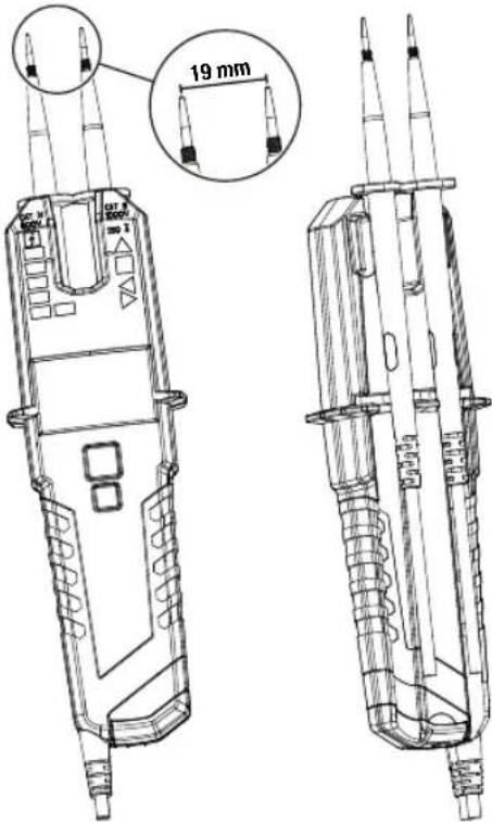
Test Probe Attachment to Main Body
You can attach one or both test probes to the main body of the tester to free up your hands while measuring. If you attach both test probes you will have a distance of 19 mm which fits perfect into mains socket with 19 mm contact distance which will enable you a measurement with one hand operation.
text_image
19 mm 20 W 3.5 4.5 5.5 6.5 7.5 8.5 9.5 10.5 11.5 12.5 13.5 14.5 15.5 16.5 17.5 18.5 19.5Test Probe Storage on Back Side
natural_image
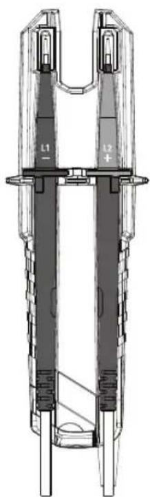
Technical line drawing of a mechanical component with labeled parts (L1, L2), no readable text or symbols beyond labelsTest Probe Protection Cover
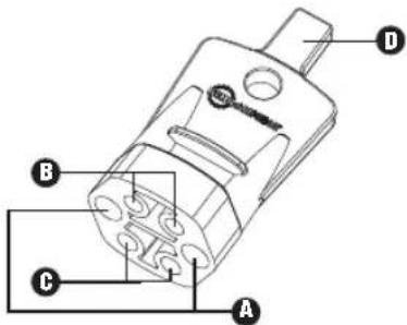
The 2100 series offers you a "Test probe protection cover" with several functions:
A Storage area for "Test probe L1-" and "Test probe L2+" to avoid any injury by penetration.
B Storage area for "4mm ∅ test probe extension"
Storage area for "GS 38 protective probe cap"
D "Opener-tool" to open UK safety sockets
text_image
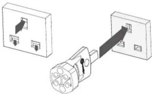
Technical diagram of a mechanical component with labeled parts A, B, and CHow to Use "Opener-Tool" to Open UK Safety Sockets
To get access to the live and neutral pin of a UK safety socket you have to release the safety covers first. This could be easily done by pressing the "Opener-tool" into earth pin of the socket.
natural_image
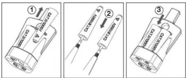
Diagram showing two electrical outlets connected to a plug, with arrows indicating direction of connection (no text or symbols present)How to Use Storage Area for "GS 38 Protective Probe Cap"
text_image
① C111000 C111000 A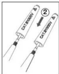
text_image
DA18000V ② DA18000V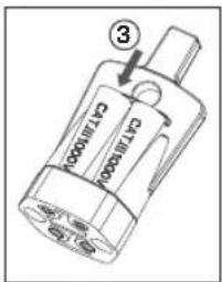
text_image
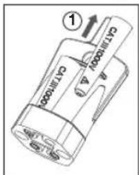
C713000 ③ C713000⚠️ Disconnect the voltage tester completely from any measuring circuit first.
- Pull out the "GS 38 protective cap" ① out of the "test probe protection cover", place onto the test probe tips ② and push firmly to secure it.
- For removal and storage ③, please perform the opposite operation.
How to Use Storage Area for "4mm ∅ Test Probe Extension"
text_image
1/4 turn ④ ⑤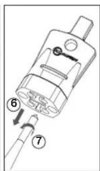
text_image
Technical diagram of a mechanical component with numbered parts indicating assembly steps
natural_image
Technical illustration of a mechanical component with a numbered callout (8), showing internal parts and a tool inserted (no text or symbols present)⚠️ Disconnect the voltage tester completely from any measuring circuit first.
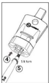
- To retrieve push the "test probe tip" into the "4mm ∅ test probe extension" ④ and twist right it approx.. ¼ turn ⑤.
- Then pull on probe ⑥ to remove "4mm ∅ test probe extension" and continue twisting until "4mm ∅ test probe extension" is tight ⑦.
- For removal please do the opposite way ⑧ and store it as shown in last picture.
SPECIFICATIONS
| Voltage Test (V) TRMS | |
| Voltage range | 1...1000 V AC (15...800 Hz),1...1500 V DC(±) |
| LED nominal voltage | +120 / -120 / 230 V: yellow LEDs400 / 690 / 1000 V: red LEDs |
| LED tolerances EN 61 | 243-3 |
| ELV indication LED >50 V AC, >120 V DC: red LED | |
| Impedance at ELV level | 320 kΩ @ 50 V AC |
| LED response time <1s at 100% of each nominal value | |
| LCD voltage range | 1.0...1000 V, AC (15...800 Hz),1.0...1500 V DC(±) |
| LCD resolution 0.1 V | (1...29.9 V), 1 V (30...1500 V) |
| LCD accuracy | ±(3% +15dgt) (1...29.9 V)±(3% +3dgt) (30...1500 V) |
| Crest Factor | 1 ... 330 V: CF3>330 ... 500 V: CF2>500 ... 1000 V: CF1.41 |
| Measurement duty cycle | 30 s ON, 240 s OFF |
| Acoustic indication ≥50 V AC, ≥120 V DC | |
| Vibration ≥50 V AC, ≥120 V DC | |
| Automatic power ON | LED/LCD: > approx. 6 V AC/DC |
| Safety current | 1 <3.5 mA at 1000 V AC,<6 mA at 1500 V DC |
| Single-Pole Phase Test (Pol) | |
| Voltage range 100...1000 VAC against earth | |
| Frequency range 50/60 Hz | |
| Acoustic indication Yes | |
| Indication same LED as ELV | |
| Continuity Test (Rx) | |
| Range 0...500 kΩ | |
| Tolerance 0% to +50% | |
| Acoustic indication Yes | |
| Indication Yellow LED | |
| Phase Rotation Indication | |
| Voltage range 170...1000 VAC phase to phase | |
| Frequency range 40...70 Hz | |
| Indication Green LEDs | |
| Current Measurement (A) TRMS | |
| Current range | 0.1...200.0 A AC |
| Resolution | 0.1 A |
| Tolerance ±(3% +5dgt) | |
| Crest Factor | 0 ... 100 A: CF2>100 ... 200 A: CF1.41 |
| Frequency range 50/60 Hz | |
| Max. conductor size | 13 mm |
| Resistance Measurement (Ω) | |
| Resistance range | 0...100 kΩ |
| Resolution | 1 Ω (1...2000 Ω), 1 kΩ (2...100 kΩ) |
| Tolerance ±(5% +10ggt) @ 25°C; | |
| Acoustic indication Sound < 20Ω | |
| Non Contact Cable Break Detector / EF (Electric Field) | |
| Range 100...1000 V AC (50/60 Hz) | |
| Voltage Mode <10V | |
| Specification | See voltage test |
| Frequency Measurement (Hz) | |
| Frequency range 1...800 Hz | |
| Resolution 1 Hz | |
| Tolerance ±(5% +5dgt) | |
| Sensetivity >10V | |
| Low Resistance Indication (L Rx) | |
| Range <20 Ω, same LED as Rx | |
| Diode Test | |
| Yes | |
| General Specifications | |
| LCD overrange indication | "OL" |
| Measurement area illumination/Flashlight | White LED |
| Backlight LED | |
| Temperature | -15...55°C operation;-20...70°C storage; No condensation |
| Humidity Max. 85% RH | |
| Operating altitude Up to 2000 m | |
| Safety rating (overvoltage category) | CAT IV / 600 V, CAT III / 1000 V |
| Safety regulations | IEC 61243-3:2014, EN 61243-3:2014,DIN VDE 0682-401:2015,IEC/EN 60529Open jaw: IEC/EN 61010-1,IEC/EN 61010-2-032 |
| Electromagnetic Compatibility (EMC) | IEC 61326-1 |
| Protection degree IP64 | |
| Pollution degree 2 | |
| Approvals, compliance |  |
| Battery 3 V (IEC LR03 | /AAA 2x 1.5 V) |
| Internal battery consumption | Approx. 120 mA |
| Battery lifetime | More than 1000 measurements(<5 s / per measurement) |
| Dimensions (HxWxD) | Approximately 210 x 63 x 37 mm(6.3 x 2.5 x 1.5 in) |
| Weight approximately | 275 g (0.61 lb) |
MAINTENANCE AND REPAIR
According to the operating instructions the voltage tester do not require any special maintenance for operation. However, if a malfunction occurs during operation, the measurement has to be stopped and a further measurement is not allowed. The unit has to be tested at our factory service department. Except for the replacement of the battery, any repair of the instrument should be performed only by an Authorized Service Center or by other qualified instrument service personnel.
⚠️ If the instrument is not used for a prolonged period, the batteries must be removed, as leaking batteries may be hazardous and cause damages.
Cleaning
Before cleaning, disconnect the voltage tester from all measuring circuits. If the instruments have become dirty due to daily use, they can be cleaned with a damp cloth and a little mild household detergent. Never use aggressive detergents or solvents for cleaning. After cleaning, do not use the instrument until it is completely dry.
BATTERY REPLACEMENT
In case of discharged batteries, the LCD will start blinking "Replace the batteries.
- Disconnect the voltage tester completely from all measuring circuits.
- Using a screwdriver, unscrew the metal screw on the battery compartment until the battery compartment cover can be removed.
NOTE: Do not unscrew the screw completely. - Remove used batteries.
- Insert new batteries, type 1.5 V IEC LR03. Ensure that the polarity is correct.
- Correctly insert battery compartment cover and screw down.
⚠️ If batteries have leaked, the instrument must no longer be used and must be tested by our Factory Service Department before it can be used again.
⚠️ Never attempt to dismantle a battery cell! The electrolyte in the cell is extremely alkaline and electro conductive. Risk of chemical burns! If electrolyte comes into contact with your skin or clothing, these spots must be rinsed immediately with water. If electrolyte gets into your eyes, rinse them immediately with clean water and consult a doctor. Please bear this in mind and also consider our environment. Do not throw used batteries into the normal household waste, but hand the batteries over to hazardous waste facilities or hazardous waste collection centers.
⚠️ Observe the currently valid national or local regulations concerning the return, recycling and disposal of used batteries and accumulators.
⚠️ Do not use the voltage tester with open battery compartment!
Germany NR6 6JB United Kingdom
Telefon: +49 (0) 7684 8009 - 0 Telefon: +44 (0) 1603 25 6662
beha-amprobe.de
beha-amprobe.com
Messwertspeicher (HOLD)....9
BATTERIEWECHSEL....14
text_image
CAT N 900V 1000 680 400 230 +120 -120 VAC DC CAT N 1000V 200 Ω Rx TRMS 1 3 4 5 6 7 8 9 10 L1 - L2 + 11 12 13 2 3 4 5 6 7 8 9 10 11 12 13text_image
Technical diagram of a mechanical component with labeled parts A, B, and Cnatural_image
Diagram showing two electrical outlets connected to a plug, with arrows indicating direction of connection (no text or symbols present)Germany NR6 6JB United Kingdom
natural_image
Technical line drawing of a mechanical component with labeled parts (L1, L2), no readable text or symbols beyond labelstext_image
Technical diagram of a mechanical component with labeled parts A, B, and Cnatural_image
Diagram showing two electrical outlets connected to a plug, with arrows indicating direction of connection (no text or symbols present)Germany NR6 6JB United Kingdom
Tel: +49 (0) 7684 8009 - 0 Tel: +44 (0) 1603 25 6662
beha-amprobe.de
beha-amprobe.com
text_image
L1 - L2 +text_image
Technical diagram of a mechanical component with labeled parts A, B, and Cnatural_image
Diagram showing two electrical outlets connected to a plug, with arrows indicating direction of connection (no text or symbols present)text_image
Diagram showing three steps of a battery component with labeled parts and arrows indicating assembly or installation.Germany NR6 6JB United Kingdom
text_image
L1 - L2 +text_image
Technical diagram of a mechanical component with labeled parts A, B, and Cnatural_image
Diagram showing two electrical outlets connected to a plug with arrows indicating connection (no text or symbols present)Germany NR6 6JB United Kingdom
Telefoon: +49 (0) 7684 8009 - 0 Telefoon: +44 (0) 1603 25 6662
Stroommeting (A) TRMS....8
Weerstandsmeting (Ω) 8
Contactloze kabelbreukdetector / EF (elektrisch veld) 8
Spanningsmodus "<10V": 1V...1000VAC/1500VDC.....8
Frequentiemeting (Hz)....9
Aanduiding lage weerstand (L Rx)....9
Diode Test (←) 9
Data Hold (HOLD) 9
natural_image
Technical line drawing of a mechanical component with two vertical arms and labeled sections (L1, L2), no readable text or symbols present.Beschermdop testsonde
text_image
Technical diagram of a mechanical component with labeled parts A, B, and Cnatural_image
Diagram showing two electrical outlets connected to a plug, with arrows indicating direction of connection (no text or symbols present)Germany NR6 6JB United Kingdom
Telephone: +49 (0) 7684 8009 - 0 Telephone: +44 (0) 1603 25 6662
text_image
HOLD DC 888.8 Hz AC V A KΩ V A Ω EF <10V Hz L Rx ←natural_image
Technical line drawing of a mechanical component with labeled parts (L1, L2), no readable text or symbols beyond labelstext_image
Technical diagram of a mechanical component with labeled parts A, B, and CComo utilizar a "Ferramenta de abertura" para abrir tomadas de segurança do RU
natural_image
Diagram showing two electrical outlets connected to a plug with a cable, no text or symbols presentGermany NR6 6JB United Kingdom
Telefon: +49 (0) 7684 8009 - 0 Telefon: +44 (0) 1603 25 6662
beha-amprobe.de
beha-amprobe.com
natural_image
Technical line drawing of a mechanical component with labeled parts (L1, L2), no readable text or symbols beyond labelstext_image
Technical diagram of a mechanical component with labeled parts A, B, and Cnatural_image
Diagram showing two electrical outlets connected to a plug, with arrows indicating direction of connection (no text or symbols present)Germany NR6 6JB United Kingdom
Puhelin: +49 (0) 7684 8009 - 0 Puhelin: +44 (0) 1603 25 6662
beha-amprobe.de
beha-amprobe.com
text_image
L1 - L2 +text_image
Technical diagram of a mechanical component with labeled parts A, B, and Cnatural_image
Diagram showing two electrical socket connections with a plug inserted into a wall socket (no text or symbols present)text_image
Cylindrical ①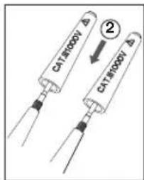
text_image
CATR000V Δ ② CATR000V Δ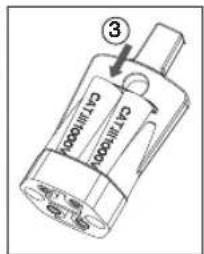
text_image
3 C17000 C17000text_image
Technical diagram of a mechanical component with numbered parts, likely illustrating a tool or assembly step.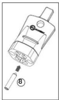
natural_image
Technical diagram of a mechanical component with numbered parts (no text or symbols)Germany NR6 6JB United Kingdom
Telefon: +49 (0) 7684 8009 - 0 Telefon: +44 (0) 1603 25 6662
beha-amprobe.de
beha-amprobe.com
natural_image
Technical line drawing of a mechanical component with labeled parts (L1, L2, +), no readable text or symbols beyond labelstext_image
Technical diagram of a mechanical component with labeled parts A, B, and Cnatural_image
Diagram showing two electrical outlets connected to a plug, with arrows indicating direction of connection (no text or symbols present)text_image
CFL1000 ③text_image
Technical diagram of a mechanical component with numbered parts and directional arrows indicating assembly or connection.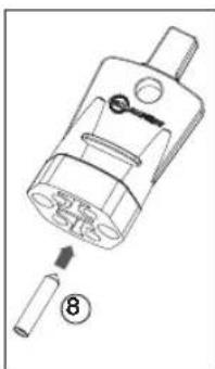
natural_image
Technical line drawing of a mechanical component with a numbered callout (8), showing internal structure without any text or symbols.KONSERWACJA I NAPRAWA
Germany NR6 6JB United Kingdom
Telefon: +49 (0) 7684 8009 - 0 Telefon: +44 (0) 1603 25 6662
beha-amprobe.de
beha-amprobe.com
Nederland – hovedkontor\*\*
Science Park Eindhoven 5110
5692 EC Son
Nederland
Telefon: +31 (0) 40 267 51 00
beha-amprobe.com
Datahold (HOLD)....9
VEDLIKEHOLD OG REPARASJON ....13
UTSKIFTING AV BATTERI ....14
text_image
CAT N BOOY 1000 690 400 230 +120 -120 VAC DC CAT N BOOY 200 Ω Rx TRMS 1 2 3 4 5 6 7 8 L1 - L2+ 10 9 11 12 13 VAC DC 8888.0V AC V A Q EF A <10V Hz L Rx - 10.3 h VAC DC VAC 2100-Delta Sensetopenter test transductionnatural_image
Technical line drawing of a mechanical component with labeled parts L1 and L2 (no text or symbols beyond labels)Beskyttelsesdeksel for prøvesonde
2100-serien har et «beskyttelsesdeksel for prøvesonde» med flere funksjoner:
text_image
Technical diagram of a mechanical component with labeled parts A, B, and Cnatural_image
Diagram showing two electrical outlets connected to a plug, with arrows indicating direction of connection (no text or symbols present)Slik bruker du lagringsområdet for «GS 38 beskyttende sondehette»
text_image
① ② ③⚠️⚠️ Koble spenningstesteren helt fra målekretsen för testing.
VEDLIKEHOLD OG REPARASJON
Germany NR6 6JB United Kingdom
Telefon: +49 (0) 7684 8009 - 0 Telefon: +44 (0) 1603 25 6662
beha-amprobe.de
beha-amprobe.com
Holland - Hovedkontor**
Science Park Eindhoven 5110
5692 EC Son
Holland
Telefon: +31 (0) 40 267 51 00
beha-amprobe.com
Vekselstrøm (AC): Vekselstrøm-ikonet (AC) lyser +Jævnstrøm (DC): Jævnstrømikonet (DC) lyser - Jævnstrøm (DC): - ikonet og jævnstrømikonet (DC) lyser
natural_image
Technical line drawing of a mechanical component with labeled parts (L1, L2, +), no readable text or symbols beyond labelstext_image
Technical diagram of a mechanical component with labeled parts A, B, and Cnatural_image
Diagram showing two electrical outlets connected to a plug, with arrows indicating direction of connection (no text or symbols present)- Catalog
- Application notes
• Product specifications - User manuals
Beha-Amprobe®
Division of Fluke Corp. (USA)
Science Park
Eindhoven 5110
5692 EC Son
The Netherlands
+31 (0) 40 267 51 00
beha-amprobe.com

Please Recycle