ProInstall200EUR - Measuring equipment Beha-Amprobe - Free user manual and instructions
Find the device manual for free ProInstall200EUR Beha-Amprobe in PDF.

| Product type | Multifunction electrical installation tester |
| Brand and model | Beha-Amprobe ProInstall200EUR |
| Dimensions | 11 cm (W) x 26 cm (L) x 13 cm (H) |
| Weight | 1.5 kg (with batteries) |
| Power supply | 6 AA 1.5 V batteries (alkaline supplied) or rechargeable NiCd/NiMH 1.2 V |
| Battery life | 200 hours at rest |
| Main functions | Voltage and frequency, insulation resistance (100-1000 V), continuity, loop/line impedance (no trip and high current), prospective short-circuit current (PSC), RCD test (trip time and current, types AC, A, B, selective), earth resistance, phase rotation, automatic RCD test |
| Display | Backlit digital screen, main and secondary display, terminal and mode indicators |
| Memory | Up to 1399 measurements with set, subset, and identification numbers |
| Data interface | IR port for transfer to PC via Amprobe software |
| Electrical safety | CAT III 500 V, CAT IV 300 V, double insulation (class II) |
| Protection rating | IP40 |
| Operating temperature | 0 °C to 40 °C |
| Relative humidity | 80 % RH from 10 to 30 °C, 70 % RH from 30 to 40 °C |
| Maximum altitude | 2000 m |
| Electromagnetic compatibility | EN 61326-1:2006 |
| Protection fuse | T3.15 A, 500 V, 1.5 kA (6.3 x 32 mm) |
| Maintenance | Clean with a damp cloth and mild detergent; annual calibration recommended |
| Repairability | Return to an authorized Beha-Amprope service center; user-replaceable fuse |
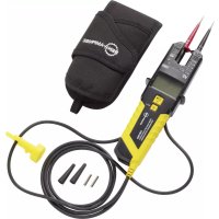
| Supplied accessories | 3 test leads, 1 mains cord, 3 alligator clips, 3 probes, 1 remote probe, CD-ROM, carrying case, padded strap |
| Warranty | 2 years (excluding batteries, fuses, and accidental damage) |
Frequently Asked Questions - ProInstall200EUR Beha-Amprobe
User questions about ProInstall200EUR Beha-Amprobe
0 question about this device. Answer the ones you know or ask your own.
Ask a new question about this device
Download the instructions for your Measuring equipment in PDF format for free! Find your manual ProInstall200EUR - Beha-Amprobe and take your electronic device back in hand. On this page are published all the documents necessary for the use of your device. ProInstall200EUR by Beha-Amprobe.
USER MANUAL ProInstall200EUR Beha-Amprobe
Telaris Multifunction Electrical Installation Tester Series
Telaris ProInstall-100-EUR
Telaris ProInstall-200-EUR
Telaris ProInstall-100-D
Telaris ProInstall-200-D
Telaris ProInstall-100-CH
Telaris ProInstall-200-CH
Telaris ProInstall-100-DK
User Manual

text_image
ENG GER FRE ITA SPA SWE FIN POL DAN NOR DUTTelaris Multifunction Electrical Installation Tester Series
Telaris ProInstall-100-EUR Telaris ProInstall-200-EUR Telaris ProInstall-100-D Telaris ProInstall-200-D Telaris ProInstall-100-CH Telaris ProInstall-200-CH Telaris ProInstall-100-DK
User Manual
Limited Warranty and Limitation of Liability
Your Beha-Amprobe product will be free from defects in material and workmanship for two years from the date of purchase unless local laws require otherwise. This warranty does not cover fuses, disposable batteries or damage from accident, neglect, misuse, alteration, contamination, or abnormal conditions of operation or handling. Resellers are not authorized to extend any other warranty on the behalf of Beha-Amprobe. To obtain service during the warranty period, return the product with proof of purchase to an authorized Beha-Amprobe Service Center or to an Beha-Amprobe dealer or distributor. See Repair Section for details. THIS WARRANTY IS YOUR ONLY REMEDY. ALL OTHER WARRANTIES - WHETHER EXPRESS, IMPLIED OR STATUTORY - INCLUDING IMPLIED WARRANTIES OF FITNESS FOR A PARTICULAR PURPOSE OR MERCHANTABILITY, ARE HEREBY DISCLAIMED. MANUFACTURER SHALL NOT BE LIABLE FOR ANY SPECIAL, INDIRECT, INCIDENTAL OR CONSEQUENTIAL DAMAGES OR LOSSES, ARISING FROM ANY CAUSE OR THEORY. Since some states or countries do not allow the exclusion or limitation of an implied warranty or of incidental or consequential damages, this limitation of liability may not apply to you.
Repair
All Beha-Amprobe tools returned for warranty or non-warranty repair or for calibration should be accompanied by the following: your name, company's name, address, telephone number, and proof of purchase. Additionally, please include a brief description of the problem or the service requested and include the test leads with the meter. Non-warranty repair or replacement charges should be remitted in the form of a check, a money order, credit card with expiration date, or a purchase order made payable to Beha-Amprobe.
In-warranty Repairs and Replacement – All Countries
Please read the warranty statement and check your battery before requesting repair. During the warranty period, any defective test tool can be returned to your Beha-Amprobe distributor for an exchange for the same or like product. Please check the "Where to Buy" section on beha-amprobe.com for a list of distributors near you.
Non-warranty Repairs and Replacement – Europe
European non-warranty units can be replaced by your Beha-Amprobe distributor for a nominal charge. Please check the "Where to Buy" section on beha-amprobe.com for a list of distributors near you.
Beha-Amprobe
Division and reg. trademark of Fluke Corp. (USA)
Germany* United Kingdom The Netherlands - Headquarters**
In den Engematten 14 52 Hurricane Way Science Park Eindhoven 5110
79286 Glottertal Norwich, Norfolk 5692 EC Son
Germany NR6 6JB United Kingdom The Netherlands
Phone: +49 (0) 7684 8009 - 0 Phone: +44 (0) 1603 25 6662 Phone: +31 (0) 40 267 51 00
beha-amprobe.de
beha-amprobe.com
beha-amprobe.com
*(Correspondence only – no repair or replacement available from this address. European customers please contact your distributor.)
**single contact address in EEA Fluke Europe BV
CONTENTS
INTRODUCTION....3
SAFETY 3
UNPACKING THE TESTER ....4
Using the Rotary Switch....5
Understanding the Pushbuttons....5
Understanding the Display 6
Input Terminals 8
Using the IR Port 8
Error Codes......8
Power-On Options....9
MAKING MEASUREMENTS 10
Measuring Volts and Frequency 10
Measuring Insulation Resistance 10
Measuring Continuity 11
Measuring Loop/Line Impedance 11
Loop impedance (line to protective earth I-pe) 12
Earth resistance testing by loop method 13
Loop impedance (Hi current trip mode) in IT systems 13
Line impedance 13
Measuring RCD Tripping Time....14
Measuring RCD Tripping Current 16
RCD Testing in IT Systems.... 17
Alternative procedure 18
Measuring Earth Resistance 18
Testing Phase Sequence 19
MEMORY MODE....20
Storing a Measurement....21
Recalling a Measurement....21
Clearing Memory 21
UPLOADING TEST RESULTS....22
MAINTAINING THE TESTER....22
Cleaning 22
Testing and Replacing the Batteries....23
Testing the Fuse....24
DETAILED SPECIFICATIONS ......24
Features by Model....24
General Specifications 24
ELECTRICAL MEASUREMENT SPECIFICATIONS 25
Continuity (RLO) 25
Insulation Resistance (RISO) 26
No Trip and Hi Current Modes RCD/FI 26
Prospective Short Circuit Current Test (PSC/IK) 27
RCD TESTING 27
RCD Types Tested 27
Test Signals....28
RCD Types Tested....28
Maximum Trip Time....29
RCD/FI-Tripping Current Measurement/Ramp Test (lΔN) 29
MAINS WIRING TEST....30
OPERATING RANGES AND UNCERTAINTIES PER EN 61557....30
The Amprobe Model Telaris ProInstall-100 and Telaris ProInstall-200 are battery powered electrical installation testers. This manual applies to all models. All figures show the Model Telaris ProInstall-200.
These testers are designed to measure and test the following:
• Voltage and Frequency
• Insulation Resistance (EN61557-2)
• Continuity (EN61557-4)
- Loop/Line Resistance (EN61557-3)
- Residual Current Devices (RCD) Tripping Time (EN61557-6)
• RCD Tripping Current (EN61557-6)
• Earth Resistance (EN61557-5)
• Phase Sequence (EN61557-7)
SYMBOLS
 | Caution! Risk of electric shock. |
 | Caution! Refer to the explanation in this manual. |
 | Double insulated (Class II) equipment |
 | Consult user documentation |
 | Earth (Ground). |
 | Fuse. |
 | Conforms to requirements of European Union and European Free Trade Association. |
 | Conforms to relevant Australian standards |
 | Do not use in distribution systems with voltages higher than 550 V. |
 | CAT III Testers are designed to protect against transients in fixedequipment installations at the distribution level; CAT IV Testers are designed to protect against transients from the primary supply level (overhead or underground utility service). |
| [T28Z] | Do not dispose this product as unsorted municipal waste. Contact aqualified recycler. |
SAFETY INFORMATION
A Warning identifies hazardous conditions and actions that could cause bodily harm or death. A Caution identifies conditions and actions that could damage the tester or cause permanent loss of data.
⚠️⚠️Warnings: Read Before Using
To prevent possible electrical shock, fire, or personal injury:
- Do not use in CAT III or CAT IV environments without the protective cap installed. The protective cap decreases the possibility of arc flash caused by short circuits.
- Use the product only as specified, or the protection supplied by the product can be compromised.
- Do not use the product around explosive gas, vapor or in damp or wet environments.
- Do not use test leads if they are damaged. Examine the test leads for damaged insulation, exposed metal, or if the wear indicator shows. Check test lead continuity.
- Use only current probes, test leads, and adapters supplied with the product.
- Measure a known voltage first to make sure that the product operates correctly.
- Do not use the product if it is damaged.
- Have an approved technician repair the product.
- Do not apply more than the rated voltage between the terminals or between each terminal and earth ground.
- Remove test leads from the tester before the tester case is opened.
- Do not operate the product with covers removed or the case open. Hazardous voltage exposure is possible.
- Use caution when working with voltages above 30 V ac rms, 42 V ac peak, or 60 V dc.
- Use only specified replacement fuses.
- Use the correct terminals, function, and range for measurements.
- Keep fingers behind the finger guards on the probes.
- Connect the common test lead before the live test lead and remove the live test lead before the common test lead.
- Replace the batteries when the low battery indicator shows to prevent incorrect measurements.
- Use only specified replacement parts.
- Do not use the tester in distribution systems with voltages higher than 550 V.
- Comply with local and national safety codes. Use personal protective equipment (approved rubber gloves, face protection, and flame-resistant clothes) to prevent shock and arc blast injury where hazardous live conductors are exposed.
UNPACKING AND INSPECTION
Your shipping carton should include:
1 Telaris ProInstall-100 or Telaris ProInstall-200
6 batteries 1.5V AA Mignon
3 Test leads
1 Mains test lead
3 Alligator clips
3 Test probe
1 Remote probe
1 CD-ROM with user manual
1 Carrying case
1 Padded Strap
If any of the items are damaged or missing, return the complete package to the place of purchase for an exchange.
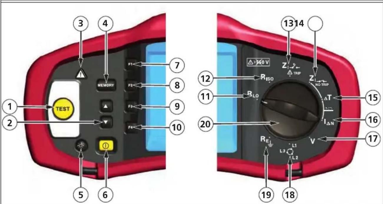
Using the Rotary Switch
Use the rotary switch (Figure 1 and Table 4) to select the type of test you want to perform.
⚠️Warnings
Do not use in CAT III or CAT IV environments without the protective cap installed. The protective cap decreases the exposed probe metal to <4mm. This decreases the possibility of arc flash from short circuits.
Understanding the Pushbuttons
Use the rotary switch to select the type of test you want to perform. Use the pushbuttons to control operation of the tester, select test results for viewing, and scroll through selected test results.
text_image
3 4 1 2 1 2 5 6 7 MEMORY F1 F2 F3 F4 TEST ① ② ③ ④ ⑤ ⑥ ⑦ ⑧ ⑨ ⑩ ⑪ ⑫ ⑬ ⑭ ⑮ ⑯ ⑰ ⑱ ⑲ ⑳ ㉑ ㉒ ㉓ ㉔ ㉕ ㉖ ㉗ ㉘ ㉙ ㉚ ㉛ ㉜ ㉝ ㉞ ㉟ ㉳ ㉴ ㉵ ㉶ ㉷ ㉸ ㉹ ㉺ ㉻ ㉼ ㉽ ㉾ ㉿ ㉒ ㉓ ㉔ ㉕ ㉖ ㉗ ㉘ ㉙ ㉚ ㉛ ㉜ ㉝ ㉟ ㉟a ㉟b ㉟c ㉟d ㉟e ㉟f ㉟g ㉟h ㉟i ㉟j ㉟k ㉟l ㉟m ㉟n ㉟o ㉟p ㉟q ㉟r ㉟s ㉟t ㉟u ㉟v ㉟w ㉟x ㉟y ㉟z| Number | Measurement Function |
| 1 | Starts the selected test. The TEST key is surrounded by a “touch pad”. The touch pad measures the potential between the operator and the tester's PE terminal. If you exceed a 100 V threshold, the ▲ symbol above the touch pad is illuminated. |
| 2 | • Scroll memory locations.• Set memory location codes. |
| 3 Above the touch pad is illuminated. | |
| 4 | • Enters Memory mode.• Activates memory soft key selections (F1, F2, F3, or F4). |
| 5 Turns the backlight on and off. | |
| 6 | Turns the tester on and off. The tester will also shut off automatically is there is no activity for 10 minutes. |
| 7 | • Loop input select (L-N, L-PE).• Voltage input select (L-N, L-PE, N-PE).• RCD current rating (10, 30, 100, 300, 500, 1000 mA• Memory SELECT. |
| 8 | • RCD Current multiplier (x1/2, x1, x5)• Memory STORE. |
| 9 | Select RCD: Type AC (sinusoidal), Type AC Selective, Type A (half-wave), Type A Selective, Type B (smooth DC), or Type B Selective.Memory RECALL. |
| 10 | RCD test polarity (0, 180 degrees).Insulation test voltage (100, 250, 500, or 1000 V).Memory CLEAR. |
| 11 Continuity. | |
| 12 Insulation resistance. | |
| 13 Loop impedance — Hi current trip mode | |
| 14 Loop impedance — No trip mode. | |
| 15 RCD tripping time. | |
| 16 RCD tripping level. | |
| 17 Volts | |
| 18 Phase rotation. | |
| 19 Earth resistance. | |
| 20 Rotary switch. | |
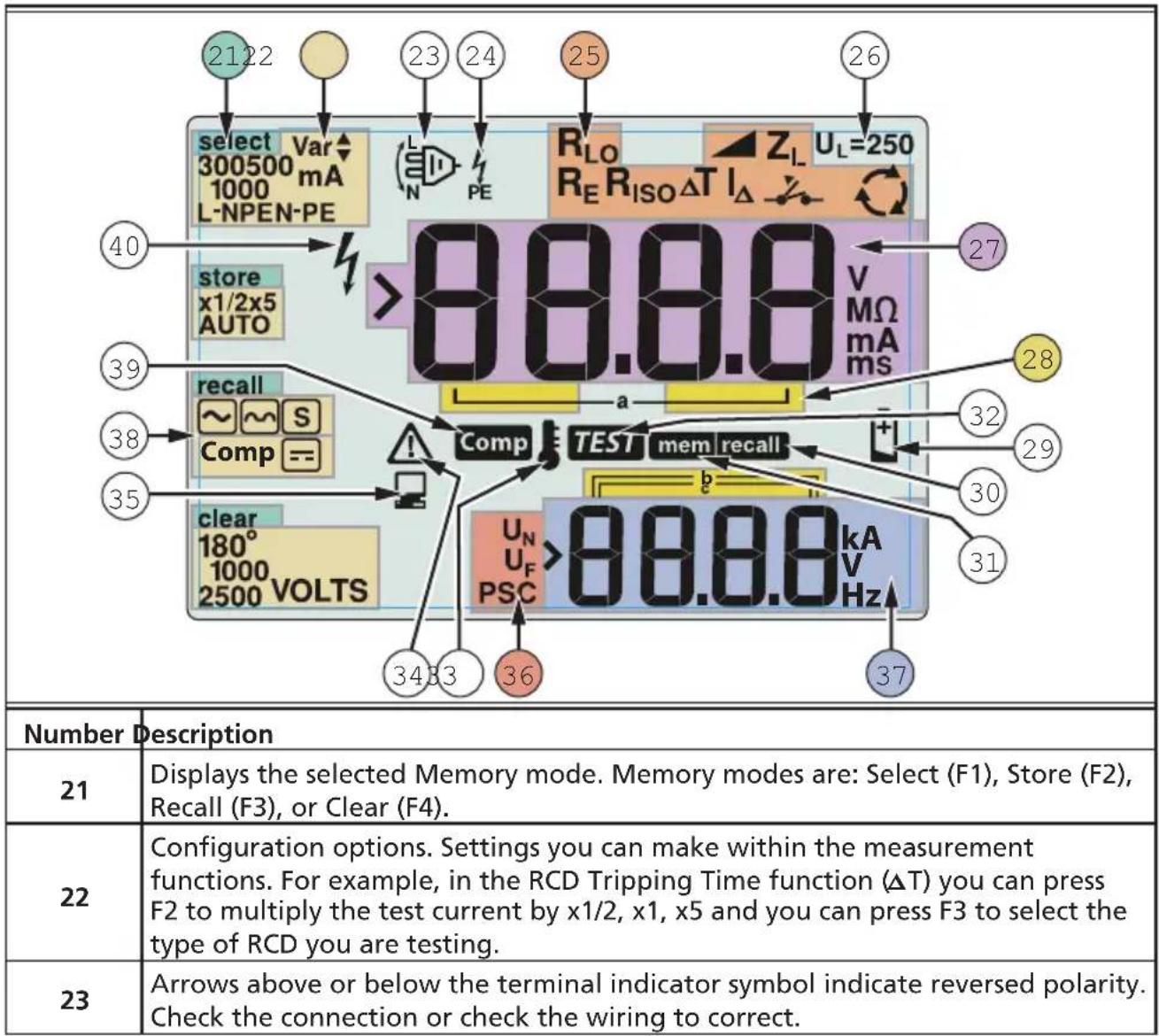
Understanding the Display
other
| Component | Value | | :--- | :--- | | select Var▲300500 mA1000 L-NPEN-PE | 2122 | | select Var▲300500 mA1000 L-NPEN-PE | 23 | | select Var▲300500 mA1000 L-NPEN-PE | 24 | | select Var▲300500 mA1000 L-NPEN-PE | 25 | | select Var▲300500 mA1000 L-NPEN-PE | 26 | | R_LO RE R_ISO ΔT I_Δ | Z_L U_L=250 | | R_LO RE R_ISO ΔT I_Δ | 27 | | store x1/2x5 AUTO | 40 | | store x1/2x5 AUTO | 39 | | recall ~ S Comp == | 38 | | recall ~ S Comp == | 35 | | Clear 180° 1000 2500 VOLTS | 34 | | Clear 180° 1000 VOLTS | 33 | | COMP = a Test mem recall b PSC >88.8.8 kA V Hz | 36 | | Comp = a Test mem recall b PSC >88.8.8 kA V Hz | 37 | Number Description 21 Displays the selected Memory mode. Memory modes are: Select (F1), Store (F2), Recall (F3), or Clear (F4). 22 Configuration options. Settings you can make within the measurement functions. For example, in the RCD Tripping Time function (ΔT) you can press F2 to multiply the test current by x1/2, x1, x5 and you can press F3 to select the type of RCD you are testing. 23 Arrows above or below the terminal indicator symbol indicate reversed polarity. Check the connection or check the wiring to correct.| 24 | Terminal indicator symbol. A terminal indicator symbol with a dot (O) in the center indicates the terminal is used for the selected function. The terminals are:• L (Line)• PE (Protective Earth)• N (Neutral) | |||
| 25 | Indicates the selected rotary switch setting. The measurement value in the primary display also corresponds to the switch setting. Rotary switch settings are | |||
| R_ISO | Insulation RCD trip time | T | ||
| R_LO | Continuity RCD trip current | I_ | ||
| Z_1 | Loop no trip Earth | R_E | ||
| Z_1 | Loop hi current trip Phase Rotation | |||
| 26 | Indicates the preset fault voltage limit. The default setting is 50 V. Some locations require the fault voltage be set to 25 V, as specified by local electrical codes. Press F4 when you turn on the tester to toggle the fault voltage between 25 V and 50 V. The value you set will appear on the display and will be saved when you turn the tester off. | |||
| 27 Primary display and measurement units. | ||||
| 28 | Memory locations. See page 37 for detailed information on using memory locations. | |||
| 29 | Low battery icon. See “Testing and Replacing the Batteries” on page 41 for additional information on batteries and power management. | |||
| 30 Appears when you press the Recall button and you are looking at stored data. | ||||
| 31 Appears when you press the Memory button. | ||||
| 32 | Appears when you press the Test button. Disappears when the test is completed. | |||
| 33 | Appears when the instrument is overheated. The Loop test and RCD functions are inhibited when the instrument is overheated. | |||
| 34 | Appears when an error occurs. Testing is disabled. See “Error Codes” on page 16 for a listing and explanation of possible error codes. | |||
| 35 Appears when the instrument is uploading data using Amprobe PC software. | ||||
| 36 | Name of the secondary measurement function. U_N - Test voltage for insulation test. U_F - Fault voltage. Measures neutral to earth.PSC - Prospective Short Circuit. Calculated from measured voltage and impedance | |||
| 37 | Secondary display and measurement units. Some tests will return more than one result or return a computed value based on the test result. This will occur with:• Volts • RCD switching time• Insulation tests • RCD tripping current• Loop / line impedance | |||
| 38 Press F3 to compensate the test lead for the continuity function. | ||||
| 39 Appears when a compensation value for the test exists. | ||||
| 40 Potential danger. Appears when measuring or sourcing high voltages. | ||||
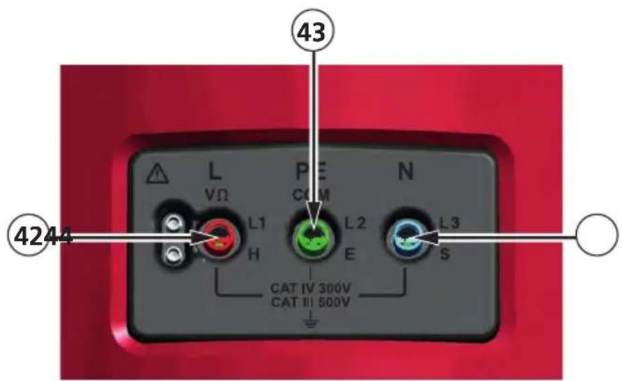
Input Terminals
Use the rotary switch to select the type of test you want to perform.
text_image
43 L VΩ L1 H P CUM L2 E N L3 S CAT IV 300V CAT III 500V 4244| Number | Description |
| 42 | L (Line) |
| 43 PE | (Protective Earth) |
| 44 N (Neutral) | |
Using the IR Port
The Model Telaris ProInstall-100 and Telaris ProInstall-200 have an IR (infrared) port, see Figure 23, which allows you to connect the tester to a computer and upload test data using a Amprobe PC software. This automates your troubleshooting or recording process, reduces the possibility of manual error and allows you to collect, organize, and display test data in a format that meets your needs. See “Uploading Test Results” on page 40 for additional information on using the IR port.
Error Codes
Various error conditions are detected by the tester and are indicated with the ⚠️ icon, "Err", and an error number on the primary display. See table below. These error conditions disable testing and, if necessary, stop a running test.
Figure 6. Error Display
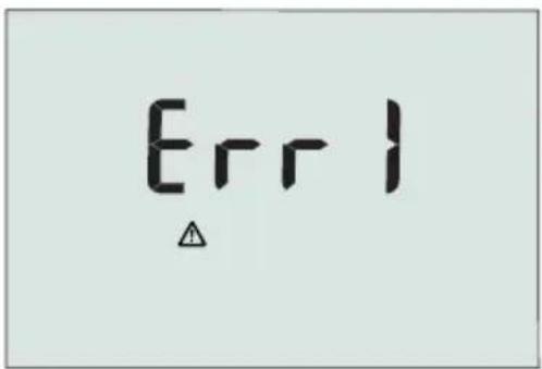 Figure 6. Error Display Figure 6. Error Display | ||
| Error Condition Code Solution | ||
| Self-test Fails 1 Return the tester to a Amprobe Service Center. | ||
| Over-temp 2 Wait w | while the tester | cools down. |
| Fault Voltage 4 | Check the installation, in particular, the voltage between N and PE. | |
| Excessive Probe Resistance | 6 | Put the stakes deeper into the soil. Tamp down the soil directly around the stakes. Pour water around the stakes but not at the earth ground under test. |
Power-On Options
To select a power-on option, press and the function key simultaneously and then release the button. Power-on options are retained when the tester is turned OFF. See Table below.
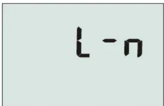
text_image
L-nUK - Mode Selected Automatic Lead
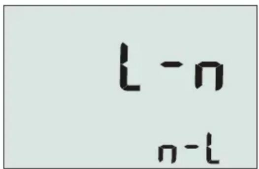
text_image
l-n n-lSwapping Mode Selected
Figure 7. Lead Swapping Modes
| Keys Power-on Options | |
 | Line and Neutral Swap mode. Two modes of operation are available. You can configure the tester to operate in L-n mode or L-n n-L mode, see Figure 7.In L-n mode, the L and N phase conductors must NEVER be reversed. This is a requirement in some regions including the UK. The icon appears on the display indicating that the system L and N conductors are swapped and testing is inhibited. Investigate and rectify the cause of this system fault before proceeding. L-n mode also changes the RCD x1/2 trip time duration to 2 seconds as required in the UK.In L-n n-L mode, the unit allows the L and N phase conductors to be swapped and testing will continue.Note: In locations where polarized plugs and outlets are used, a swapped lead icon ( ) may indicate that the outlet was wired incorrectly. Correct this problem before proceeding with any testing. |
 | Fault voltage limit. Toggles the fault voltage between 25 V and 50 V. The default is 50 V. |
 | View the tester serial number. Primary display shows the initial four digits and the secondary display shows the next four digits. |
 | Continuity beeper toggle. Toggles the continuity beeper on and off. The default is on. |
Measuring Volts and Frequency
text_image
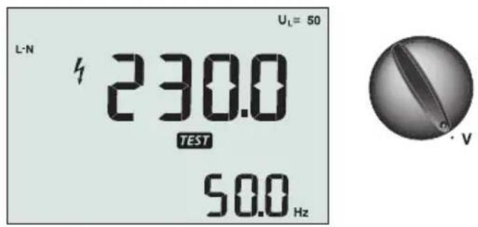
L-N 230.0 TEST 50.0 Hz U_L = 50 · VFigure 8. Volts Display/Switch and Terminal Settings
To measure voltage and frequency:
- Turn the rotary switch to the V position.
- Use all (red, blue, and green) terminals for this test. You can use test leads or mains cord when measuring AC voltage.
- The primary (upper) display shows the AC voltage. The tester reads AC voltage to 500 V. Press F1 to toggle the voltage reading between L-PE, L-N, and N-PE.
- The secondary (lower) display shows mains frequency.
⚠ Warning
It is not possible to check reliably the connections of N- and PE-circuits in the socket by voltage measurement. To ensure this, we suggest to verify this while performing Loop and Line impedance measuring.
Reason for this is that the voltages L-N, L-PE and N-PE are measured by the tester at the same time and will be influenced by open wires together with resistances (loads) and capacitances of the installation network in combination with internal resistances of the tester itself.
This issue happens especially when N is missing/open and can lead to wrong reading.
Measuring Insulation Resistance
text_image
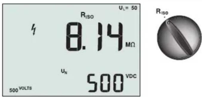
RISO UL= 50 8.14 MΩ UN 500 VDC 500 VOLTS RISOFigure 9. Insulation Resistance Display/Switch and Terminal Settings
⚠ Warning
To avoid electric shock, measurements should only be performed on de-energized circuits.
To measure insulation resistance:
- Turn the rotary switch to the Riso position.
- Use the L and PE (red and green) terminals for this test.
-
Use the F4 to select the test voltage. Most insulation testing is performed at 500 V, but observe local test requirements.
-
Press and hold TEST until the reading settles
Note: Testing is inhibited if voltage is detected in the line.
- The primary (upper) display shows the insulation resistance.
- The secondary (lower) display shows the actual test voltage.
Note: For normal insulation with high resistance, the actual test voltage (UN) should always be equal to or higher than the programmed voltage. If insulation resistance is bad, the test voltage is automatically reduced to limit the test current to safe ranges.
Measuring Continuity
text_image
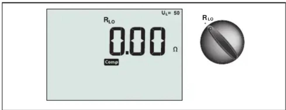
U_L = 50 R_LO 0.00 Ω Comp R_LOFigure 10. Continuity Zero Display/Switch and Terminal Settings
A continuity test is used to verify the integrity of connections by making a high resolution resistance measurement. This is especially important for checking Protective Earth connections.
Note: In countries where electrical circuits are laid out in a ring, it is recommended that you make an end-to-end check of the ring at the electrical panel.
⚠ Warning
- Measurements should only be performed on de-energized circuits.
- Measurements may be adversely affected by impedances or parallel circuits or transient currents.
To measure continuity:
- Turn the rotary switch to the RLO position.
- Use the L and PE (red and green) terminals for this test.
- Before making a continuity test, short connect the test leads. Press and hold F3 until the comp annunciator appears. The tester measures probe resistance, stores the reading in memory, and subtracts it from readings. The resistance value is saved even when power is turned off so you don't need to repeat the operation every time you use the instrument.
Note: Be sure the batteries are in good charge condition before you compensate the test leads.
- Press and hold until the reading settles. If the continuity beeper is enabled, the tester beeps continuously for measured values less than 2 Ω and there is no stable reading beep for measured values greater than 2 Ω. If a circuit is live, the test is inhibited and the AC voltage appears in the secondary (lower) display.
Measuring Loop/Line Impedance
text_image
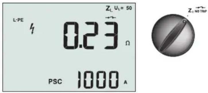
L-PE 0.23 Ω PSC 1000 A Z₁ Uₗ = 50 Z₁ NO TRIPFigure 11. Loop/Line Impedance/Switch and Terminal Settings
Loop Impedance (Line to Protective Earth L-PE)
Loop impedance is source impedance measured between Line (L) and Protective Earth (PE). You can also ascertain the Prospective Earth Fault Current (PSC) that is the current that could potentially flow if the phase conductor is shorted to the protective earth conductor. The tester calculates the PSC by dividing the measured mains voltage by the loop impedance. The loop impedance function applies a test current that flows to earth. If RCDs are present in the circuit, they may trip. To avoid tripping, always use the ZI No Trip function on the rotary switch. The no trip test applies a special test that prevents RCDs in the system from tripping. If you are certain no RCDs are in the circuit, you can use the ZI Hi Current function for a faster test.
Note: If the L and N terminals are reversed, the tester will auto-swap them internally and continue testing. If the tester is configured for UK operation, testing will halt. This condition is indicated by symbol ( ).
Tip: We recommend to measure in addition to each loop impedance measurement also the line impedance to ensure correct wiring.
This will proof the correct connection of live (L) and neutral (N) wire for short circuit and overload protection.
To measure loop impedance no trip mode:
⚠ Warning
To prevent tripping RCDs in the circuit:
• Always use the Z position for loop measurements.
- Preload conditions can cause the RCD to trip.
- An RCD with a nominal fault current of 10 mA will trip.
Note: To do a Loop impedance test in a circuit with a 10 mA RCD, we recommend a trip time RCD test. Use a nominal test current of 10 mA and the factor x 12 for this test.
If the fault voltage is below 25 V or 50 V, dependent on the local requirement, the loop is good. To calculate the loop impedance, divide the fault voltage by 10 mA (Loop impedance = fault voltage x 100).
- Turn the rotary switch to the Z_1 NO TRIP position.
- Connect all three leads to the L, PE, and N (red, green, and blue) terminals of the tester. Only the calibrated test lead which are in scope of supply must be used! The resistance of the calibrated test leads is subtracted from the result automatically.
- Press F1 to select L-PE. The display shows the Z_L and indicator.
- Connect all three leads to the L, PE, and N of the system under test or plug the mains cord into the socket under test.
text_image
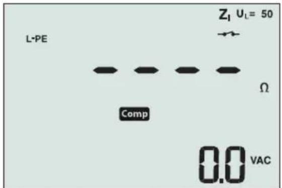
L-PE Z₁ Uₗ = 50 Comp Ω 0.0 VACFigure 12. Display After Zeroing
- Press and release TEST. Wait for the test to complete. The primary (upper) display shows the loop impedance. The secondary (lower) display shows the prospective short current (PSC) in amps or kilo amps.
This test will take several seconds to complete. If the mains is disconnected while the test is active, the test automatically terminates.
Note: Errors may occur due to preloading the circuit under test.
To measure loop impedance—Hi current trip mode:
If no RCDs are present in the system under test, you can use the high current Line Earth (L-PE) loop impedance test.
- Turn the rotary switch to the Z_1 position.
- Connect all three leads to the L, PE, and N (red, green, and blue) terminals of the tester. Only the calibrated test lead which are in scope of supply must be used! The resistance of the calibrated test leads is subtracted from the result automatically.
- Press F1 to select L-PE. The 🔍 appears to indicate that hi current trip mode is selected.
- Repeat Steps 4 through 8 from the preceding test.
⚠ Warning
The symbol ⚡ on the LCD indicates the high current loop mode - any RCDs in the system will trip - ensure there are no RCDs present.
Loop impedance (Hi current trip mode) in IT systems
The impedance being measured by a phase to earth test depends on the condition of the IT-system. It should be a very high impedance on a healthy system. Low impedance values may be caused by a shorted disneuter, loads connected to the system, or an existing first fault condition. This is not a common test as the state of the system must be known before you can determine the significance of the measured value.
Use the mains test lead but do not connect the N-wire to the instrument, so just the PE and L inputs are used. See figure 18a.
Note: An RCD will trip during this test, in case the impedance is low.
Line Impedance
Line impedance is source impedance measured between Line conductors or Line and Neutral. This function allows the following tests:
• Line to Neutral loop impedance.
Tip: We recommend to measure in addition to each loop impedance measurement also the line impedance to ensure correct wiring.
This will proof the correct connection of live (L) and neutral (N) wire for short circuit and overload protection.
• Line to Line impedance in 3-phase systems.
- Two wire L-PE loop measurement when Neutral is not available. This is a way of making a high current, 2-wire loop measurement. Therefore connect Line to L input and PE to N input. It cannot be used on circuits protected by RCDs because it will cause them to trip.
- Prospective Short Circuit Current (PSC). PSC is the current that can potentially flow if the phase conductor is shorted to the neutral conductor or another phase conductor. The tester calculates the PSC current by dividing the measured mains voltage by the line impedance.
text_image
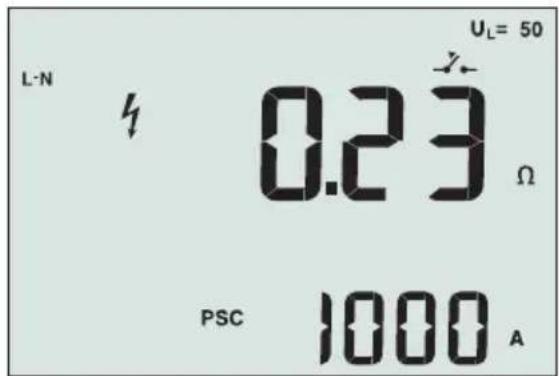
L-N 4 0.23 Ω PSC 1000 A UL= 50Figure 14. Line Impedance Display
To measure line impedance:
- Turn the rotary switch to the Z_1 - Y_0 -TRIP position. The LCD indicates that the high current loop mode is selected by displaying the symbol.
- Connect the red lead to the L (red) and the blue lead to the N (blue). Only the calibrated test lead which are in scope of supply must be used! The resistance of the calibrated test leads is subtracted from the result automatically.
- Press F1 to select L-N.
⚠ Warning
At this step, be careful not to select L-PE because a high current loop test will take place. Any RCDs in the system will trip if you proceed.
Note: Connect the leads in a single-phase test to the system live and neutral. To measure line-to-line impedance in a 3-phase system, connect the leads to 2 phases.
- Press and release TEST . Wait for the test to complete.
• The primary (upper) display shows the line impedance.
• The secondary (lower) display shows the Prospective Short Circuit Current (PSC).
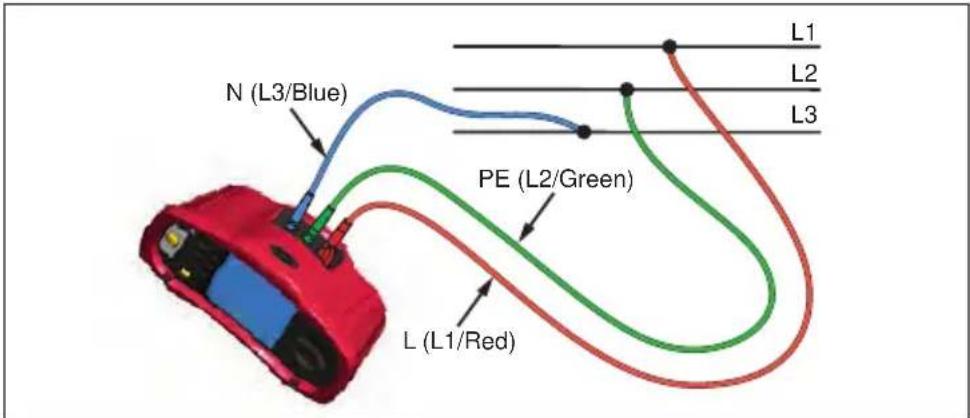
Use the connection shown in Figure 15 when measuring in a 3-phase 500 V system.
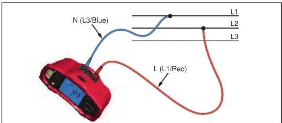
text_image
N (L3/Blue) L1 L2 L3 L (L1/Red)Figure 15. Measuring in a 3-Phase System
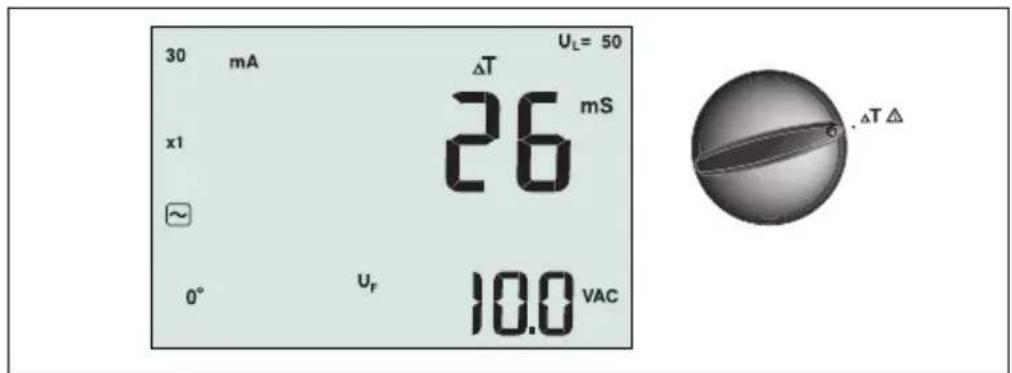
Measuring RCD Tripping Time
text_image
30 mA x1 ~ 0° uF 26 mS 10.0 VAC ΔT UL= 50 ΔTΔFigure 16. RCD Tripping Time Display/Switch and Terminal Settings
In this test, a calibrated fault current is induced into the circuit, causing the RCD to trip. The meter measures and displays the time required for the RCD to trip. You can perform this test with test leads or using the mains cord. The test is performed with a live circuit.
You can also use the tester to perform the RCD tripping time test in Auto mode, which makes it easier for one person to perform the test.
Note: When measuring trip time for any type of RCD, the tester first does a pretest to determine if the actual test will cause a fault voltage exceeding the limit (25 or 50 V).
To avoid having an inaccurate trip time for S type (time delay) RCDs, a 30 second delay is activated between the pretest and the actual test. This RCD type needs a delay because it contains RC circuits that are required to settle before applying the full test.
⚠ Warning
- Leakage currents in the circuit following the residual current protection device may influence measurements.
- The displayed fault voltage relates to the rated residual current of the RCD.
- Potential fields of other earthing installations may influence the measurement.
- Equipment (motors, capacitors) connected downstream of the RCD may cause considerable extension of the tripping time.
Note: If the L and N terminals are reversed, the tester will auto-swap them internally and continue testing. If the tester is configured for UK operation, testing will halt and you will need to determine why the L and N are swapped.
This condition is indicated by symbol ( ) .
Type A and type B RCDs do not have the 1000 mA option available.
To measure RCD tripping time:
- Turn the rotary switch to the T position.
- Press F1 to select the RCD current rating (10, 30, 100, 300, 500, or 1000 mA).
- Press F2 to select a test current multiplier (x 12 , x 1, x 5, or Auto). Normally you will use x 1 for this test.
- Press F3 to select the RCD test-current waveform:
- AC current to test type AC (standard AC RCD) and type A (pulse-DC sensitive RCD)
- Half-wave current to test type A (pulse-DC sensitive RCD)
\~ S Delayed response to test S-type AC (time delayed AC RCD)

S Delayed response to S-type A (time delayed pulse-DC sensitive RCD)

– Smooth-DC current to test type B RCD

S Delayed response to S-type B (time delayed smooth-DC current RCD)
- Press F4 to select the test current phase, 0^ or 180^ . RCDs should be tested with both phase settings, as their response time can vary significantly depending on the phase
Note: For RCD type B (☐) or S-type B (☐) you must test with both phase
settings, all three test leads are required.
-
Press and release TEST. Wait for the test to complete.
-
The primary (upper) display shows the trip time.
- The secondary (lower) display shows the fault voltage related to the rated residual current.
To measure RCD tripping time using Auto mode:
- Plug the tester into the outlet.
- Turn the rotary switch to the T position.
- Press F1 to select the RCD current rating (10, 30, or 100 mA).
- Press F2 to select Auto mode.
- Press F3 to select the RCD test-current waveform.
- Press and release TEST
The tester supplies 12x the rated RCD current for 310 or 510 ms (2 seconds in the UK). If the RCD trips, the test terminates. If the RCD does not trip, the tester reverses phase and repeats the test. The test terminates if the RCD Trips.
If the RCD does not trip, the tester restores the initial phase setting and supplies 1x the rated RCD current. The RCD should trip and the test results appear in the primary display.
- Reset the RCD.
- The tester reverses phases and repeats the 1x test. The RCD should trip and the test results appear in the primary display.
- Reset the RCD.
- The tester restores the initial phase setting and supplies 5x the rated RCD current for up to 50 ms. The RCD should trip and the test results appear in the primary display.
- Reset the RCD.
- The tester reverses phase and repeats the 5x test. The RCD should trip and the test results appear in the primary display.
- Reset the RCD.
- You can use the ▲ arrow keys to review test results. The first result shown is the last measurement taken, the 5x current test. Press the down arrow key ▲ to move backward to the first test at ½x the rated current.
- Test results are in temporary memory. If you want to store the test results, press MEMORY and proceed as described in "Storing and Recalling Measurements" on page 37 of this manual.
Note: You must store each result separately after you select it with the arrow keys.
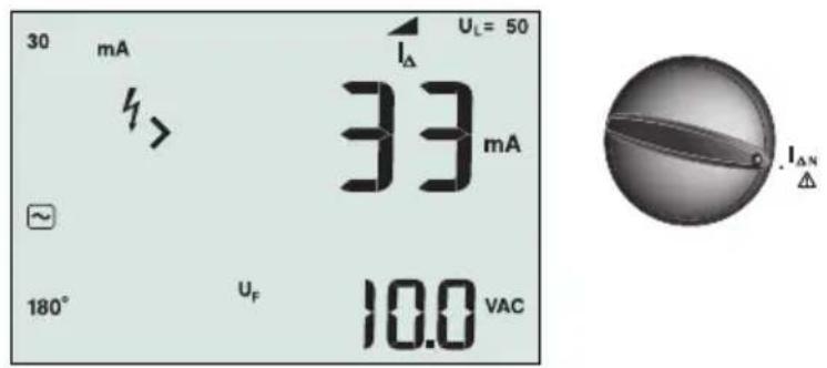
Measuring RCD Tripping Current
text_image
30 mA IΔ UL= 50 33 mA 180° U_F 10.0 VAC IΔNFigure 17. RCD Tripping Current/Switch and Terminal Settings
This test measures the RCD tripping current by applying a test current and then gradually increasing the current until the RCD trips. You can use the test leads or mains cord for this test. A 3 wire connection is required for testing of RCD type B.
⚠ Warning
- Leakage currents in the circuit following the residual current protection device may influence measurements.
- The displayed fault voltage relates to the rated residual current of the RCD.
- Potential fields of other earthing installations may influence the measurement.
Note: If the L and N terminals are reversed, the tester will auto-swap them internally and continue testing. If the tester is configured for UK operation, testing will halt and you will need to determine why the L and N are swapped.
This condition is indicated by symbol ( )
Type A and type B RCDs do not have the 1000 mA option available.
To measure RCD tripping current:
- Turn the rotary switch to the I_ N position.
- Press F1 to select the RCD current rating (10, 30, 100, 300, or 500 mA).
-
Press F2 to select the RCD test-current waveform:
-
AC current to test type AC (standard AC RCD) and type A (pulse-DC sensitive RCD)
- Half-wave current to test type A (pulse-DC sensitive RCD)
\~ S Delayed response to test S-type AC (time delayed AC RCD)
S Delayed response to S-type A (time delayed pulse-DC sensitive RCD) -
Smooth-DC current to test type B RCD
S Delayed response to S-type B (time delayed smooth-DC current RCD) -
Press F4 to select the test current phase, 0° or 180°. RCDs should be tested with both phase settings, as their response time can vary significantly depending on the phase.
Note: For RCD type B (☐) or S-type B (☐), you must test with both phase settings, all three test leads are required.
- Press and release TEST. Wait for the test to complete.
• The primary (upper) display shows the trip time.
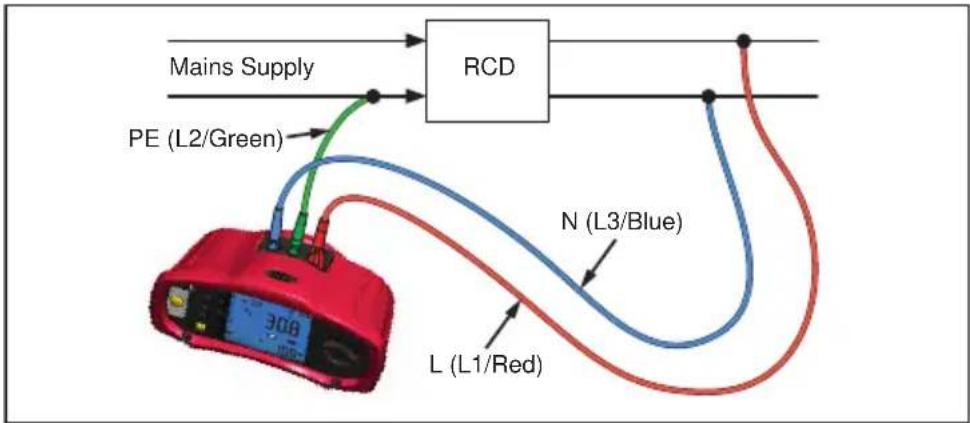
RCD testing in IT systems
RCD testing at locations with IT systems requires a special test procedure because the Protective Earth connection is grounded locally and is not tied directly to the power system. The test is conducted at the electrical panel using probes. Use the connection shown in Figure 18 when performing RCD testing on IT electrical systems.
flowchart
graph TD
    A["Mains Supply"] --> B["RCD"]
    B --> C["PE (L2/Green)"]
    B --> D["N (L3/Blue)"]
    B --> E["L (L1/Red)"]
Figure 18. Connection for RCD Testing on IT Electrical Systems
The test current flows through the upper side of the RCD, into the L terminal, and returns though the PE terminal.
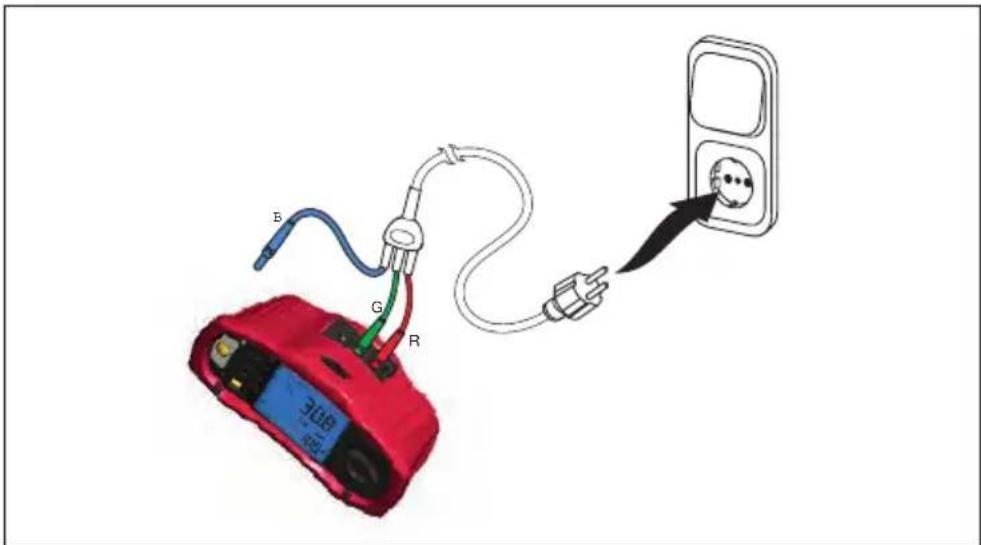
Alternative procedure
In IT systems, when testing an RCD at a mains socket: Use the mains test lead but do not connect the N-wire to the instrument, so just the PE and L inputs are used. See figure 18a.
text_image
Diagram showing a red electronic device connected to a wall-mounted socket with labeled wires (B, G, R) and a cable.Figure 18a.
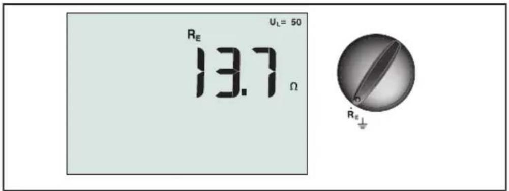
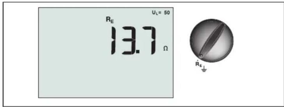
Measuring Earth Resistance
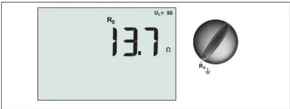
text_image
U_L = 50 R_E 13.7 Ω R_E⊥Figure 19. Earth Resistance Display/Switch and Terminal Settings
The earth resistance test is a 3-wire test consisting of two test stakes and the earth electrode under test. This test requires an accessory stake kit. Connect as shown in Figure 20.
- Best accuracy is achieved with the middle stake at 62 % of the distance to the far stake. The stakes should be in a straight line and wires separated to avoid mutual coupling.
- The earth electrode under test should be disconnected from the electrical system when conducting the test. Earth resistance testing should not be performed on a live system.

text_image
Earthing rod under test PE (E) N (S) L (H) 62% L LFigure 20. Earth Resistance Test Connection
To measure earth resistance:
- Turn the rotary switch to the R_E position.
-
Press and release (TEST). Wait for the test to complete.
-
The primary (upper) display shows the earth resistance reading.
- Voltage detected between the test rods will be displayed in the secondary display. If greater than 10 V, the test is inhibited.
- If the measurement is too noisy, Err 5 will be displayed. (The measured value accuracy is degraded by the noise). Press the down arrow (→) to display the measured value. Press the up arrow (→) to return to the Err 5 display.
- If the probe resistance is too high, Err 6 is displayed. Probe resistance may be reduced by driving the test stakes further into the earth or wetting the earth around the test stakes.
Testing Phase Sequence
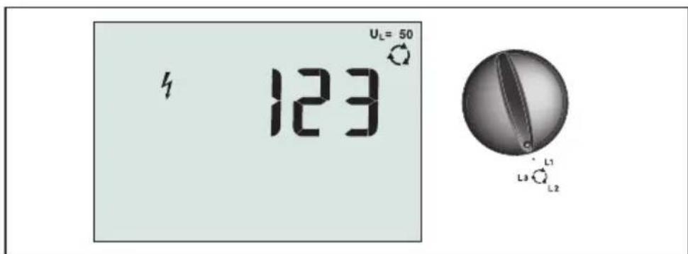
text_image
4 123 Uₗ = 50 L₁ L₃ L₂Figure 21. Phase Sequence Display/Switch and Terminal Settings
Use the connection shown in Figure 22 for a phase sequence test connection.

text_image
N (L3/Blue) PE (L2/Green) L (L1/Red) L1 L2 L3Figure 22. Phase Sequence Test Connection
To perform a phase sequence test:
-
Turn the rotary switch to the ⬆ position.
-
The primary (upper) display shows:
• 123 for correct phase sequence.
• 321 for reversed phase sequence.
- Dashes (---) instead of numbers if insufficient voltage is sensed.
Memory mode
You can store measurements on the tester:
• Telaris ProInstall-100 – up to 399
• Telaris ProInstall-200 – up to 1399
The information stored for each measurement consists of the test function and all user selectable test conditions.
Data for each measurement is assigned a data set number, data subset number, and a data id number. Memory location fields are used as described below.
| Field Description | |
| a | Use the data set field (a) to indicate a location such as a room or electrical panel number. |
| b | Use the data subset field (b) for circuit number. |
| c | The data id number field (c) is the measurement number. The measurement number automatically increments. The measurement number can also be set to a previously used value to overwrite an existing measurement. |
To enter Memory mode:
- Press the MEMORY to enter Memory mode.
The display changes to a memory mode display. In Memory mode, the MEMORY appears on the display.
The primary numeric display shows the data set number (a, 1-9999). The secondary numeric display shows the data subset number (b, 1-9999). The data id number (c, 1-9999) appears after you press F1 several times. One of the memory locations, a, b, or c, will flash to indicate that you can change the number using the arrow keys ▲.
-
To enable the data subset number to be changed, press F1. The data subset number will now be flashing. To enable the data sub number to be changed, press F1 again. The data set number will now be flashing. Press F1 again to change the data id number.
-
Press the down arrow key (▲) to decrement the enabled number or press the up arrow key (▼) to increment the enabled number. For storing data, the number can be set to any value, overwriting existing data is allowed. For recalling data, the number can only be set to used values.
Note: If you press the up or down arrow key (▲) once, the number increments or decrements by one. To accelerate the increment or decrement function, press and hold the up or down arrow.
Storing a Measurement
To store a measurement:
-
Press MEMORY to enter Memory mode.
-
Press F1 and use the arrow keys (▲) to set the data identity
-
Press F2 to save the data.
- If memory is full, FULL will appear on the primary display. Press F1 to choose another data identity, press MEMORY to exit Memory mode.
- If the memory is not full, the data will be saved, the tester will automatically exit Memory mode and the display will revert back to the previous test mode.
- If the data identity has been previously used, the display will show STO? Press F2 again to store the data, press F1 to choose another data identity, press MEMORY to exit Memory mode.
Recalling a Measurement
To recall a measurement:
-
Press MEMORY to enter Memory mode.
-
Press F3 to enter the Recall mode.
-
Use F1 and the arrow keys (▲) to set the data identity. If no data has been saved, all fields will be dashes.
-
Press F3 to recall the data. The tester display will revert to the Test mode used for the recalled test data, however, the MEMORY icon still appears, indicating the tester is still in Memory mode.
-
Press F3 to toggle between the data id screen and the recalled data screen to check the recalled data id or to select more data to recall.
-
Press MEMORY to exit Memory mode at any time.
Clearing Memory
To clear all memory
-
Press MEMORY to enter Memory mode.
-
Press F4. The primary display will show Clr?
-
Press F4 again to clear all memory locations. The Tester returns to the measurement mode.
Uploading Test Results
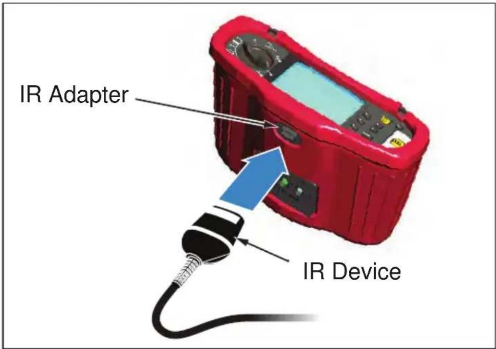
text_image
IR Adapter IR DeviceFigure 23. Attaching the IR Adapter
To upload test results:
- Connect the IR serial cable to the serial port on the PC.
- Attach the IR adapter and the device to the tester as shown in Figure 23.
- Start the Amprobe PC software program.
- Press to turn on the tester.
- Refer to the software documentation for complete instructions on how to upload data from the tester.
MAINTAINING THE TESTER
Calibration
To ensure the accuracy of the measurements it is recommended that the instrument is calibrated regularly by our service. We suggest a calibration interval of one year.
Cleaning
Periodically wipe the case with a damp cloth and mild detergent. Do not use abrasives or solvents.
Dirt or moisture in the terminals can affect readings.
To clean the terminals:
- Turn the meter off and remove all test leads.
- Shake out any dirt that may be in the terminals.
- Soak a new swab with alcohol. Work the swab around each terminal.
Testing and Replacing the Batteries
Battery voltage is continuously monitored by the tester. If the voltage falls below 6.0 V (1.0 V/cell), the low battery icon appears on the display, indicating that there is minimal battery life left. The low battery icon continues to appear on the display until you replace the batteries.
⚠ Warning
To avoid false readings, which could lead to possible electric shock or personal injury, replace the batteries as soon as the battery icon ( appears.
Be sure that the battery polarity is correct. A reversed battery can cause leakage.
Replace the batteries with six AA batteries. Alkaline batteries are supplied with the tester but you can also use 1.2 V NiCd or NiMH batteries. You can also check the battery charge so that you can replace them before they discharge.
⚠ Warning
To avoid electrical shock or personal injury, remove the test leads and any input signals before replacing the battery. To prevent damage or injury, install ONLY specified replacement fuses with the amperage, voltage, and speed ratings shown in the General Specifications section of this manual.
To replace the batteries (refer to Figure 24):
- Press Ⓐ to turn the tester off.
- Remove the test leads from the terminals.
- Remove the battery door by using a standard-blade screwdriver to turn the battery door screws (3) one-quarter turn counterclockwise.
- Press the release latch and slide the battery holder out of the tester.
- Replace the batteries and the battery door.
Note: All stored data will be lost if the batteries are not replaced within approximately one minute
- Secure the door by turning the screws one-quarter turn clockwise.
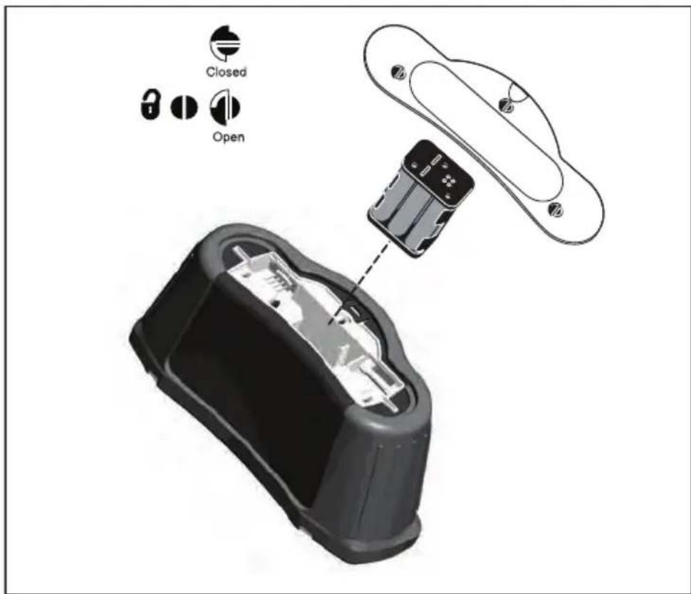
text_image
Closed OpenFigure 24. Replacing the Batteries
Testing the Fuse
- Turn the rotary switch to switch setting.
- Short the leads and press and hold TEST
- If the fuse is bad, FUSE or Err1 will appear on the display to indicate the tester is damaged and needs repair. Contact Amprobe Service for repair (see Contacting Amprobe).
DETAILED SPECIFICATIONS
Features
| Measurement Function Telaris Pro | Install-100 Telaris Pro | Install-200 |
| Voltage & Frequency √ √ | ||
| Wiring polarity checker √ √ | ||
| Insulation Resistance √ √ | ||
| Loop & Line Resistance √ √ | ||
| Prospective Short-Circuit current (PSC/IK) | √ | √ |
| RCD switching time √ √ | ||
| RCD tripping level √ √ | ||
| Automatic RCD test sequence None √ | ||
| Test pulse current sensitive RCDs (Type A) | √ | √ |
| Test smooth dc sensitive RCDs (Type B) | None √ | |
| Earth Resistance None √ | ||
| Phase Sequence Indicator √ √ | ||
| Other Features | ||
| Illuminated Display | √ √ | |
| Memory | √ √ | |
| Memory, Interface | ||
| Computer Interface | √ √ | |
| Software | √ √ | |
| Included Accessories | ||
| Soft case | √ √ | |
| Remote control probe | √ √ | |
General Specifications
| Specification | Characteristic |
| Size | 11 cm (L) x 26 cm (W) x 13 cm (H) |
| Weight (with batteries) | 1.5 kg |
| Battery size, quantity Type AA, 6 ea. | |
| Battery type | Alkaline supplied.Usable with 1.2 V NiCd or NiMH batteries (not supplied) |
| Battery life (typical) 200 hours idling | |
| Fuse T3.15 A, 500 V, 1.5 kA 6.3 x | 32 mm |
| Operating Temperature 0 °C to 40 °C | |
| Relative Humidity 80% 10 to 30°C; 70% 30 to 40°C | |
| Operating Altitude 0 to 2000 meters | |
| Sealing IP 40 | |
| EMC Complies with EN61326-1: 2006 | |
| Safety Complies with EN61010-1 | Ed 3.Complies with EN/IEC 61010-031:2002+A1:2008.Overvoltage Category: 500 V/CAT III300 V/CAT IVMeasurement Category III is for measurements performed in the building installation. Examples are distribution panels, circuit breakers, wiring and cabling.Category IV equipment is designed to protect against transients from the primary supply level, such as an electrical meter or an overhead or underground utility service.Performance EN61557-1, EN61557-2, EN61557-3, EN61557-4, EN61557-5, EN61557-6, EN61557-7 Second edition. EN61557-10 First edition. |
| Pollution Degree 2 | |
| Maximum voltage between any terminal and earth ground | 500 V |
Electrical Measurement Specifications
The accuracy specification is defined as ±(% reading +digit counts) at 23 ^±5 ^,≤80 % RH. Between -10 ^ and 18 ^ and between 28 ^ and 40 ^ , accuracy specifications may degrade by 0,1× (accuracy specification) per ^ . The following tables can be used for the determination of maximum or minimum display values considering maximum instrument operating uncertainty per EN61557-1, 5.2.4.
Voltage Measurement
| Range Resolution | Accuracy | 50 Hz – 60 Hz | Input Impedance | Overload Protection |
| 500 V 0.1 V 2% + | 3digits 3.3 MΩ | 660 V rms |
Continuity Testing ( R_LO )
| Range (Autoranging) | Resolution | Open Circuit Voltage | Accuracy |
| 20 Ω | 0.01 Ω | >4 V | ±(3 % + 3 digits) |
| 200 Ω | 0.1 Ω | >4 V | ±(3 % + 3 digits) |
| 2000 Ω | 1 Ω | >4 V | ±(3 % + 3 digits) |
| Note: The number of possible continuity tests with a fresh set of batteries is 2500. | |||
| Range R_LO | Test Current |
| 7.5 Ω 210 mA | |
| 35 Ω 100 mA | |
| 240 Ω 20 mA | |
| 2000 Ω 2 mA |
| Test Probe Zeroing Press the | F3 to compensate the test probe.Can subtract up to 2 Ω of lead resistance.Error message for >2 Ω. |
| Live Circuit Detection Inhibits | ts test if terminal voltage >10 V ac detected prior to initiation of test. |
Insulation Resistance Measurement ( R_ISO )
| Test Voltages 100-250-500-1 | 1000 V |
| Accuracy of Test Voltage (at rated test current) | +10 %, -0 % |
| Test Voltage | Insulation Resistance Range | Resolution Test | Current Accuracy | |
| 100 V | 100 kΩ to 20 MΩ | 0.01 MΩ | 1 mA @ 100 kΩ | ±(5 % + 5 digits) |
| 20 MΩ to 100 MΩ | 0.1 MΩ | ±(5 % + 5 digits) | ||
| 250 V | 10 kΩ to 20 MΩ | 0.01 MΩ | 1 mA @ 250 kΩ | ±(5 % + 5 digits) |
| 20 MΩ to 200 MΩ | 0.1 MΩ | ±(5 % + 5 digits) | ||
| 500 V | 10 kΩ to 20 MΩ | 0.01 MΩ | 1 mA @ 500 kΩ | ±(5 % + 5 digits) |
| 20 MΩ to 200 MΩ | 0.1 MΩ | ±(5 % + 5 digits) | ||
| 200 MΩ to 500 MΩ | 1 MΩ | ±10 % | ||
| 1000 V | 100 kΩ to 200 MΩ | 0.1 MΩ | 1 mA @ 1 MΩ | ±(5 % + 5 digits) |
| 200 MΩ to 1000 MΩ | 1 MΩ | ±10 % | ||
| Note: The number of possible insulation tests with a fresh set of batteries is 1750. | ||||
| Auto Discharge | Discharge time constant <0.5 second for C = 1 μF or less. |
| Live Circuit Detection Inhibits | ts test if terminal voltage >30 V prior to |
| Maximum Capacitive Load | Operable with up the 5 μF load. |
Loop/Line Impedance: No Trip and Hi Current Modes
| Mains Input Voltage Range | 100 - 500 V ac (50/60 Hz) |
| Input Connection (soft key selection) | Loop Impedance: phase to earth |
| Line impedance: phase to neutral | |
| Limit on Consecutive Tests Automatic shutdown when internal components are too hot. There is also a thermal shutdown for RCD tests. | |
| Maximum Test Current @ 400 V | 12 A sinusoidal for 10 ms |
| Maximum Test Current @ 230 V | 7 A sinusoidal for 10 ms |
| Range Resolution | tion Accuracy | [1] |
| 20 Ω 0.01 Ω | No Trip mode: | ±(4 % + 6 digits) |
| Hi Current mode: ±(3 % + 4 digits) | ||
| 200 Ω 0.1 Ω | ±(5 %) | |
| 2000 Ω 1 Ω | ±6 % | [2] |
| Note:[1] Valid for resistance of neutral circuit <20 Ω and up to a system phase angle of 30 °.[2] Valid for mains voltage >200 V. | ||
Prospective Short Circuit Current Test (PSC/ I_k )
| Computation Prospective Short Circuit Current (PSC/IK) determined by dividing measured mains voltage by measured loop (L-PE) resistance or line (L-N) resistance, respectively. | ||
| Range 0 to 10 kA | ||
| Resolution and Units Resolution | on Units | |
| I_K < 1000 A 1 A | ||
| I_K > 1000 A 0.1 kA | ||
| Accuracy | Determined by accuracy of loop resistance and mains voltage measurements. | |
RCD Testing
RCD Types Tested
| RCD Type[6] | Telaris ProInstall-100 | Telaris ProInstall-200 | |
| AC^[1] | G^[2] | √ | √ |
| AC | S^[3] | √ | √ |
| A^[4] | G | √ | √ |
| AS | √ | √ | |
| B^[5] | G | √ | |
| AS | √ | ||
| Note: [1] AC – Responds to ac [2] G – General, no delay [3] S – Time delay [4] A – Responds to pulsed signal [5] B – Responds to smooth dc [6] RCD test inhibited for V >265 ac RCD tests permitted only if the selected current, multiplied by earthing resistance, is <50V. | |||
Test Signals
| RCD Type Test Signal Description | |
| AC(sinusoidal) | The waveform is a sinewave starting at zero crossing, polarity determined by phase selection (0 ° phase starts with low to high zero crossing, 180 ° phase starts with high to low zero crossing). The magnitude of the test current is I_ n × Multiplier for all tests. |
| A(half wave) | The waveform is a half wave rectified sinewave starting at zero, polarity determined by phase selection (0 ° phase starts with low to high zero crossing, 180 ° phase starts with high to low zero crossing). The magnitude of the test current is 2.0 x I_ n (rms) x Multiplier for all tests for I_ n = 0.01A . The magnitude of the test current is 1.4 x I_ n (rms) x Multiplier for all tests for all other I_ n ratings. |
| B (DC) This is a smooth DC current according to EN61557-6 Annex A | |
RCD Types Tested
| Test Function | RCD Current Selection | |||||
| 10 mA 30 | mA 100 mA | [1] | 300 mA[1] | 500 mA[1] | 1000 mA[2] | |
| X 12 , 1 √ √ √ √ | √ √ | |||||
| X 5 √ √ √ | ||||||
| Ramp √ √ √ √ | √ √ | |||||
| Auto √ √ √ | ||||||
| Note:Mains voltage 100 V – 265 V ac, 50/60 Hz[1] Type B RCDs require mains voltage range of 195 V – 265 V.[2] Type AC RCDs only. | ||||||
| Current Multiplier | *RCD Type | Measurement Range | Trip Time Accuracy | |
| Europe UK | ||||
| X 1⁄2 G 310 ms | 2000 ms ± (2% Reading + 2ms) | |||
| X 1⁄2 S 510 ms | 2000 ms ± (2% Reading + 2ms) | |||
| X 1 | G | 310 ms | 310 ms | ± (2% Reading + 2ms) |
| X 1 | S | 510 ms | 510 ms | ± (2% Reading + 2ms) |
| X 5 | G | 50 ms | 50 ms | ± (2% Reading + 2ms) |
| X 5 | S | 160 ms | 160 ms | ± (2% Reading + 2ms) |
| Note:*G – General, no delay*S – Time delay | ||||
Maximum Trip Time
| RCD I | _N | Trip Time Limits |
| AC G, A, B X 1 Less than 300 ms | ||
| AC G-S, A-S, B-S X 1 Between 130 ms and 500 ms | ||
| AC G, A, B X 5 Less than 40 ms | ||
| AC G-S, A-S, B-S X 5 Between 50 ms and 150 ms | ||
RCD/FI-Tripping Current Measurement/Ramp Test ( I_ N )
| Current Range Step Size | Size | Measurement Range | Measurement Accuracy | |
| Type G Type S | ||||
| 30 % to 110 % of RCD rated current[1] | 10 % of I_ N [2] | 300 ms/step 5 | 00 ms/step ±5 % | |
| Notes[1] 30 % to 150 % for Type A I_ N >10 mA30 % to 210 % for Type A I_ N = 10 mA20 % to 210 % for Type BSpecified trip current ranges (EN 61008-1):50 % to 100 % for Type AC35 % to 140 % for Type A (>10 mA)35 % to 200 % for Type A (≤10 mA)50 % to 200 % for Type B[2] 5% for Type B | ||||
Earth Resistance Test
Telaris ProInstall-200 only. This product is intended to be used to measure installations in process plants, industrial installations, and residential applications.
| Range Resolution Accuracy | |||
| 200 Ω | 0.1 Ω | ±(3 % + 5 digits) | |
| 2000 Ω | 1 Ω | ±(5 % + 10 digits) | |
| Range: RE + RPROBE [1] | Test Current |
| 2200 Ω | 3.5 mA |
| 16000 Ω | 500 μA |
| 52000 Ω | 150 μA |
| Note[1] Without external voltages | |
| Frequency | Output Voltage |
| 128 Hz | 25 V |
| Live Circuit Detection | Inhibits test if terminal voltage >10 V ac is detected prior to start of test. |
Phase Sequence Indication
| Icon | icon Phase Sequence indicator is active. |
| Display of Phase Sequence Displays “1-2-3” in digital display field for correct sequence. Displays “3-2-1” for incorrect phase. Dashes in place of a number indicate a valid determination could not be made. | |
| Mains Input Voltage Range (phase-tophase) | 100 to 500 V |
Mains Wiring Test
Icons (indicate if L-PE or L-N terminals are reversed. Instrument operation is inhibited and an error code is generated if the input voltage is not between 100 V and 500 V. The UK Loop and RCD tests are inhibited if the L-PE or the L-N terminals are reversed.
Operating Ranges and Uncertainties per EN 61557
| FUNCTION | DISPLAY RANGE | EN 61557 MEASUREMENT RANGE OPERATING ERROR | NOMINAL VALUES |
| R_LO | 0,00 Ω - 2000 Ω | 0,3 Ω - 2000 Ω± (10% + 3 dgt) | 4,0 VDC < U_Q < 12 VDC R_LO ≤ 2,00 Ω I_N ≥ 200 mA |
| R_ISO | 0,00 MΩ - 1000 MΩ | 1 MΩ - 200 MΩ± (12% + 3dgt)200 MΩ - 1000 MΩ± (15% + 5 dgt) | U_N = 100 / 250 / 500 / 1000 VDC I_N = 1,0 mA |
| Z_I | Z_I (NO TRIP)0,00 Ω - 2000 Ω | 0,5 Ω - 2000 Ω± (15% + 8 dgt) | U_N = 230 / 400 VACf = 50 / 60 Hz I_PSC = 0 A - 10,0 kA |
| Z_I (HI CURRENT)0,00 Ω - 2000 Ω | 0,3 Ω - 200 Ω± (10% + 5 dgt) | ||
| T, I_ N | T 0,0 ms - 2000 ms | 25 ms - 2000 ms± (10% + 2 dgt) | T@ 10 / 30 / 100 / 300 / 500 / 1000 mA |
| I_ N 3 mA - 550 mA | 3 mA - 550 mA± (10% + 2 dgt) | I_ N = 10 / 30 / 100 / 300 / 500 mA | |
| Volts | 0,0 VAC - 500 VAC | 50 VAC - 500 VAC± (3% + 3 dgt) | U_N = 230 / 400 VACf = 50 / 60 Hz |
| Phase | 1 : 2 : 3 | ||
| R_E | 0,0 Ω - 2000 Ω | 10 Ω - 2000 Ω± (10% + 3 dgt) | f = 123 Hz |
Telaris Multifunction Electrical Installation Tester Series
Telaris ProInstall-100-EUR Telaris ProInstall-200-EUR Telaris ProInstall-100-D Telaris ProInstall-200-D Telaris ProInstall-100-CH Telaris ProInstall-200-CH Telaris ProInstall-100-DK
Bedienungsanleitung
NR6 6JB United Kingdom
Telefon: +44 (0) 1603 25 6662
beha-amprobe.com
text_image
R_LO 0.00 Ω Comp U_L = 50 R_LOtext_image
L-PE Comp Z₁ Uₗ = 50 Ω 0.0 VACtext_image
N (L3/Blue) L1 L2 L3 L (L1/Red)text_image
Mains Supply RCD PE (L2/Green) N (L3/Blue) L (L1/Red)text_image
Diagram showing a red handheld device connected to an electrical outlet with labeled wires (B, G, R) and a cable.Abbildung 18a.
text_image
U_L = 50 R_E 13.7 Ω R_E⊥text_image
Earthing rod under test PE (E) N (S) L (H) 62% L Ltext_image
U_L = 50 4 123° L3 L1 L2text_image
N (L3/Blue) PE (L2/Green) L (L1/Red) L1 L2 L3text_image
Closed OpenTelaris Multifunction Electrical Installation Tester Series
Telaris ProInstall-100-EUR Telaris ProInstall-200-EUR Telaris ProInstall-100-D Telaris ProInstall-200-D Telaris ProInstall-100-CH Telaris ProInstall-200-CH Telaris ProInstall-100-DK
Guide d'utilisation
text_image
R_LO 0.00 Ω Comp U_L = 50text_image
L-PE Z₁ Uₗ = 50 Comp Ω 0.0 VACtext_image
N (L3/Blue) L (L1/Red) L1 L2 L3text_image
Diagram showing a red handheld device connected to an electrical outlet with labeled wires (B, G, R) and a close-up of the outlet.Figure 18a.
text_image
Earthing rod under test PE (E) N (S) L (H) 62% L Ltext_image
4 123° Uₗ = 50 L₁ L₂ L₃text_image
N (L3/Blue) PE (L2/Green) L (L1/Red) L1 L2 L3text_image
Closed OpenTelaris Multifunction Electrical Installation Tester Series
Telaris ProInstall-100-EUR Telaris ProInstall-200-EUR Telaris ProInstall-100-D Telaris ProInstall-200-D Telaris ProInstall-100-CH Telaris ProInstall-200-CH Telaris ProInstall-100-DK
text_image
L-PE Z₁ Uₗ = 50 Comp Ω 0.0 VACtext_image
N (L3/Blue) L1 L2 L3 L (L1/Red)text_image
30 mA I₁ 33 mA 180° Uₚ 10.0 VAC Uₗ = 50text_image
Diagram showing a red handheld device connected to a wall-mounted socket with labeled wires (B, G, R) and a black arrow pointing to the socket.Figura 18a.
text_image
U_L = 50 R_E 13.7 Ω Ṙ_E⊥text_image
Earthing rod under test PE (E) N (S) L (H) 62% L Ltext_image
4 123 Uₗ= 50text_image
N (L3/Blue) PE (L2/Green) L (L1/Red) L1 L2 L3Figura 22. Collegamento test sequenza fasi
text_image
Closed OpenTelaris Multifunction Electrical Installation Tester Series
Telaris ProInstall-100-EUR Telaris ProInstall-200-EUR Telaris ProInstall-100-D Telaris ProInstall-200-D Telaris ProInstall-100-CH Telaris ProInstall-200-CH Telaris ProInstall-100-DK
Manual del usuario
text_image
R_LO 0.00 Ω Comp U_L = 50text_image
L-PE Z₁ Uₗ = 50 Comp Ω 0.0 VACtext_image
N (L3/Blue) L (L1/Red) L1 L2 L3flowchart
graph TD
    A["Red Device"] --> B["RCD"]
    B --> C["Mains Supply"]
    B --> D["N (L3/Blue)"]
    B --> E["L (L1/Red)"]
    B --> F["PE (L2/Green)"]
text_image
Diagram showing a red handheld device connected to an electrical outlet with labeled wires (B, G, R) and a plug.Figura 18a.
text_image
Earthing rod under test PE (E) N (S) L (H) 62% L Ltext_image
N (L3/Blue) PE (L2/Green) L (L1/Red) L1 L2 L3text_image
Closed OpenTelaris Multifunction Electrical Installation Tester Series
Telaris ProInstall-100-EUR Telaris ProInstall-200-EUR Telaris ProInstall-100-D Telaris ProInstall-200-D Telaris ProInstall-100-CH Telaris ProInstall-200-CH Telaris ProInstall-100-DK
Användarhandbok
NR6 6JB United Kingdom
Telefon: +44 (0) 1603 25 6662
beha-amprobe.com
Alternative method 20
text_image
R_LO 0.00 Ω Comp U_L = 50text_image
U_L = 50 N PE L R_ISO 8.14 MΩ U_N 500 VDC 500 VOLTS R_ISO N PE Ltext_image
L-PE Comp Z₁ Uₗ = 50 Ω 0.0 VACtext_image
N (L3/Blue) L (L1/Red) L1 L2 L3text_image
Diagram showing a red handheld device connected to a wall-mounted socket with labeled wires (E, G, R) and a black arrow pointing to the socket.Figur 18a.
text_image
U_L = 50 R_E 13.7 Ω R_E⊥text_image
Earthing rod under test PE (E) N (S) L (H) 62% L Ltext_image
Uₗ = 50 4 123text_image
N (L3/Blue) PE (L2/Green) L (L1/Red) L1 L2 L3Figur 22. Anslutning för fassekvenstest
text_image
Closed OpenFigur 24. Byta batterier
Telaris Multifunction Electrical Installation Tester Series
Telaris ProInstall-100-EUR Telaris ProInstall-200-EUR Telaris ProInstall-100-D Telaris ProInstall-200-D Telaris ProInstall-100-CH Telaris ProInstall-200-CH Telaris ProInstall-100-DK
Käyttöohje
NR6 6JB United Kingdom
Puhelin: +44 (0) 1603 25 6662
beha-amprobe.com
text_image
RISO 8.14 MΩ UN 500 VOLTS 500 VDC UL = 50text_image
L-PE Z₁ Uₗ = 50 Comp Ω 0.0 VACtext_image
N (L3/Blue) L (L1/Red) L1 L2 L3text_image
Diagram showing a red electronic device connected to an electrical outlet with labeled wires (B, G, R) and a plug.Kuvio 18a.
text_image
U_L = 50 R_E 13.7 Ω R_E⊥text_image
Earthing rod under test PE (E) N (S) L (H) 62% L Ltext_image
N (L3/Blue) PE (L2/Green) L (L1/Red) L1 L2 L3text_image
Closed OpenTARKAT TEKNISET TIEDOT
Ominaisuudet
Telaris Multifunction Electrical Installation Tester Series
Telaris ProInstall-100-EUR Telaris ProInstall-200-EUR Telaris ProInstall-100-D Telaris ProInstall-200-D Telaris ProInstall-100-CH Telaris ProInstall-200-CH Telaris ProInstall-100-DK
NR6 6JB United Kingdom
Telefon: +44 (0) 1603 25 6662
beha-amprobe.com
TEST OKABLOWANIA SIECI....32
ZAKRESY DZIAŁANIA I NIEPEWNOŚCI WEDŁUG EN 61557....32
WPROWADZENIE
text_image
L-PE Comp Z₁ Uₗ = 50 Ω 0.0 VACtext_image
N (L3/Blue) L1 L2 L3 L (L1/Red)text_image
Diagram showing a red handheld device connected to an electrical outlet with labeled wires (B, G, R) and a cable.Rysunek 18a.
text_image
R_E 13.7 Ω U_L = 50 R_E⊥text_image
Earthing rod under test PE (E) N (S) L (H) 62% L Ltext_image
4 123° Uₗ = 50 L₁ L₂ L₃text_image
N (L3/Blue) PE (L2/Green) L (L1/Red) L1 L2 L3text_image
Closed OpenTelaris Multifunction Electrical Installation Tester Series
Telaris ProInstall-100-EUR Telaris ProInstall-200-EUR Telaris ProInstall-100-D Telaris ProInstall-200-D Telaris ProInstall-100-CH Telaris ProInstall-200-CH Telaris ProInstall-100-DK
Brugervejledning
NR6 6JB United Kingdom
Telefon: +44 (0) 1603 25 6662
beha-amprobe.com
Holland - Hovedkontor**
Science Park Eindhoven 5110
5692 EC Son
Holland
Telefon: +31 (0) 40 267 51 00
beha-amprobe.com
Alternative procedure....20
text_image
L-PE Z₁ Uₗ= 50 Comp Ω 0.0 VACtext_image
N (L3/Blue) L1 L2 L3 L (L1/Red)text_image
Diagram showing a red handheld device connected to an electrical outlet with labeled wires (B, G, R) and a plug.Fig. 18a.
text_image
U_L = 50 R_E 13.7 Ω Ṙ_E⊥text_image
Earthing rod under test PE (E) N (S) L (H) 62% L Ltext_image
4 123 Uₗ = 50 L₁ L₃ L₂text_image
N (L3/Blue) PE (L2/Green) L (L1/Red) L1 L2 L3text_image
Closed OpenTelaris Multifunction Electrical Installation Tester Series
Telaris ProInstall-100-EUR Telaris ProInstall-200-EUR Telaris ProInstall-100-D Telaris ProInstall-200-D Telaris ProInstall-100-CH Telaris ProInstall-200-CH Telaris ProInstall-100-DK
Brukerhåndbok
Begrenset garanti og ansvarsbegrensning
Beha Amprobe-produktet skal være uten defekter i materiale og utførelse i to år fra kjøpsdatoen med mindre lokale lover krever noe annet. Denne garantien dekker ikke sikringer, éngangsbatterier eller skader som skyldes uhell, vanskjøtsel, misbruk, endring, forurensning, eller unormale driftsforhold eller håndtering. Forhandlere har ikke rett til å forlenge garantier på vegne av Beha-Amprobe. For å få service i garantiperioden må du returnere produktet med kjøpsbevis til et autorisert Beha-Amprobe-servicesenter eller til en Beha-Amprobe-forhandler eller -distributør. Se avsnittet Reparasjon for mer informasjon. DENNE GARANTIEN ER DITT ENESTE BOTEMIDDEL. ALLE ANDRE GARANTIER – ENTEN DIREKTE, INDIREKTE ELLER LOVBESTEMTE – INKLUDERT UNDERFORSTÅTTE GARANTIER OM EGNETHET FOR ET SPESIELT FORMÅL ELLER SALGBARHET, FRASKRIVES HERVED. PRODUSENTEN SKAL IKKE VÆRE ANSVARLIG FOR SPESIELLE, INDIREKTE, TILFELDIGE SKADER ELLER F∅LGESKADER ELLER TAP, UANSETT ÅRSAK ELLER TEORI. Siden noen stater eller land ikke tillater fraskrivelse eller begrensning av en garanti eller av tilfeldige skader eller følgeskader, er det mulig at denne ansvarsbegrensningen ikke gjelder for deg.
Reparasjon
VEDLIKEHOLDE TESTEREN....24
Rengjøring 24
Teste og erstatte batteriene 24
Teste sikringen 25
DETALJERTE SPESIFIKASJONER....25
text_image
L-PE Z₁ Uₗ = 50 Comp Ω 0.0 VACtext_image
N (L3/Blue) L (L1/Red) L1 L2 L3Figur 15. Måle i et 3-fasesystem
flowchart
graph TD
    A["Mains Supply"] --> B["RCD"]
    B --> C["N (L3/Blue)"]
    B --> D["L (L1/Red)"]
    B --> E["PE (L2/Green)"]
text_image
Diagram showing a red handheld device connected to a wall-mounted socket with labeled wires (B, G, R) and cable routing.Figur 18a.
Måle jordmotstand
text_image
U_L= 50 R_E 13.7 Ω R_E⊥Figur 19. Visning og bryter-/kontaktinnstillinger for jordmotstand
Jordmotstandstesten er en 3-ledertest som består av to teststaker og jordelektroden under test. Denne testen krever et tilbehørstakesett. Koble som vist i figur 20.
text_image
Earthing rod under test PE (E) N (S) L (H) 62% L LFigur 20. Jordmotstandstesttilkobling
text_image
4 123 Uₗ = 50 L₁ L₂ L₃Figur 21. Visning og bryter-/kontaktinnstillinger for fasesekvens
Bruke tilkoblingen vist i figur 22 for en fasesekvenstesttilkobling.
text_image
N (L3/Blue) PE (L2/Green) L (L1/Red) L1 L2 L3Figur 22. Fasesekvenstesttilkobling
VEDLIKEHOLDE TESTEREN
Kalibrering
text_image
Closed OpenJordfeilbrytertesting Jordfeilbrytertyper testet
Telaris Multifunction Electrical Installation Tester Series
Telaris ProInstall-100-EUR Telaris ProInstall-200-EUR Telaris ProInstall-100-D Telaris ProInstall-200-D Telaris ProInstall-100-CH Telaris ProInstall-200-CH Telaris ProInstall-100-DK
TESTRESULTATEN UPLOADEN....23
DE TESTER ONDERHOUDEN 24
Reiniging....24
De batterijen testen en vervangen....24
text_image
RISO 8.14 MΩ UN 500 VOLTS 500 VDC UL = 50text_image
L-PE Z₁ Uₗ = 50 Comp Ω 0.0 VACtext_image
N (L3/Blue) L (L1/Red) L1 L2 L3text_image
Diagram showing a red handheld device connected to an electrical outlet with labeled wires (E, G, R) and a plug.Afbeelding 18a.
Aardweerstand meten
text_image
U_L = 50 R_E 13.7 Ω Ṙ_E⊥text_image
Earthing rod under test PE (E) N (S) L (H) 62% L Ltext_image
4 123° Uₗ = 50 L₁ L₂ L₃text_image
N (L3/Blue) PE (L2/Green) L (L1/Red) L1 L2 L3text_image
Closed Open- Catalog
- Application notes
• Product specifications - User manuals
Beha-Amprobe®
beha-amprobe.com
c/o Fluke Europe BV
Science Park
Eindhoven 5110
NL-5692 EC Son
Tel.: +49 (0) 7684 8009 - 0

Please Recycle