Drainex 600 - Pump ESPA - Free user manual and instructions
Find the device manual for free Drainex 600 ESPA in PDF.

| Product type | Waste water / drainage pump |
| Brand / Model | ESPA Drainex 600 |
| Max. solid passage | 65 mm |
| Max. liquid temperature | 40 °C |
| Nominal voltage | 400 V three-phase (see nameplate for exact version) |
| Frequency | 50 Hz |
| Protection rating | IPX8 |
| Motor insulation class | Class F (indicated on plate) |
| Operating mode | Continuous (S1) |
| Applications | Waste water transfer, drainage, septic tanks |
| Installation | Total immersion with level float; portable or stationary options |
| Electrical connection | Requires 30 mA residual current device and omnipolar switch |
| Motor protection | Integrated thermal protector (must be associated with a relay without automatic reset) |
| Routine maintenance | Cleaning of the impeller by disassembling the suction head; oil change every 3000 h or 1 year |
| Lubricating oil | White mineral oil of medicinal quality, quantity 0.7 L |
| Technical interventions | Reserved for ESPA Approved Technical Service (www.espa.com) |
| Disposal | No toxic materials; recycling via local collection or approved depository |
Frequently Asked Questions - Drainex 600 ESPA
User questions about Drainex 600 ESPA
0 question about this device. Answer the ones you know or ask your own.
Ask a new question about this device
Download the instructions for your Pump in PDF format for free! Find your manual Drainex 600 - ESPA and take your electronic device back in hand. On this page are published all the documents necessary for the use of your device. Drainex 600 by ESPA.
USER MANUAL Drainex 600 ESPA
natural_image
Technical line drawing of a mechanical component with flanged base and mounting bracket (no text or symbols)EN Instruction manual 10 (Translation from the original Spanish)
EN: EVIDENCE OF CONFORMITY
We declare, under our responsibility, that the products in this manual comply with the following directives and standards:
- Directive 2006/42/EC (Machine Security): Standard EN 809 and EN 60204-1
- Directive 2014/35/EU (Low voltage): Standard EN 60335-1, EN 60335-2-41
- Directive 2011/65/UE (Restriction of hazardous substances): Standard EN 50581.
- UNE-EN ISO 3744 (Noise emisión values in instruction manual)
- Directive EMC 2014/30/EU (Electromagnetic compatibility): Direttiva 2014/30/UE (Compatibilita elettro-magnetica): Standard EN 61000-6-1 y EN 61000-6-3 Norma EN 61000-6-1 e alla EN 61000-6-3
EVIDENCE OF CONFORMITY
We declare, under our responsibility, that the products in this manual comply with the following directives and standards:
- Supply of Machinery (Safety) Regulations 2008: Standard BS 809 and BS 60204-1
- Electromagnetic Compatibility Regulations 2016: Standard BS 61000-6-1 and BS 61000-6-3.
- Electrical Equipment (Safety) Regulations 2016: Standard BS 60335-1 and BS 60335-2-41.
- The Restriction of the Use of Certain Hazardous Substances in Electrical and Electronic Equipment Regulations 2012. Standard BS 50581.
Banyoles, April 15th 2021
Josep Unyó (Technical Manager)
ESPA 2025, SL
Ctra. de Mieres, s/n - 17820 Banyoles
Girona - Spain
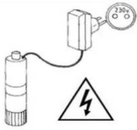
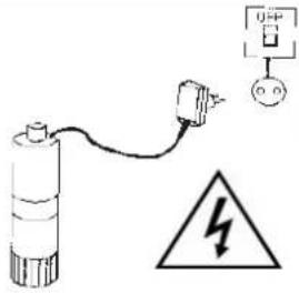
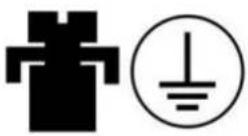
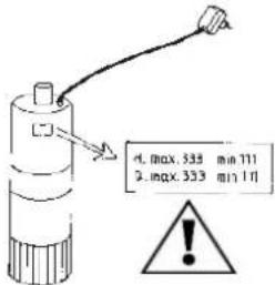
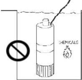
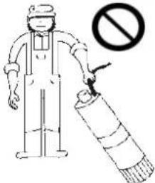
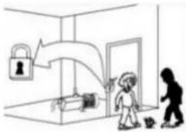
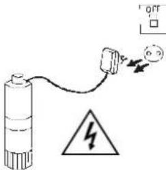
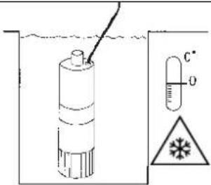
Damage prevention and safety instructions (See figure 5)
| A | Warning! Observe limitations of use. |
| B | The nameplate voltage must be the same as the mains voltage. |
| C | Connect the pump to the mains via an omnipolar switch with at least a 3 mm opening between contacts. |
| D | Install a high-sensitivity differential switch (0.03A) as extra protection against lethal electric shocks. |
| E | Connect the pump to the ground. |
| F | Use pump only within performance limits indicated on the nameplate. |
| G | Be careful with hazardous liquids and environments. |
| H | Do not carry the pump by the power cable. |
| I | This apparatus may be used by children 8 years or older and persons with reduced physical, sensory or mental capacities, or lacking experience and knowledge, if they are supervised or receive adequate training on the safe use of the apparatus and understand the dangers.Children should not be allowed to play with the apparatus.Children should not perform the ordinary cleaning and maintenance tasks without supervision. |
| J | The pump should only be dismantled by authorized personnel. |
| K | Cut out power supply before servicing pump. |
| L | Caution! Avoid icing. |
Contents
Safety precautions 10
- General information.... 11
- Application 11
- Safety....11
- Handling....11
- Installation 11
5.1. Fixing and transport.... 11
5.2. Discharge pipe assembly 12
5.3. Electrical connection 12
5.4. Control Devices 12
5.5. Pre-start checks 12
-
Starting 12
-
Maintenance 12
7.1. General Indications 12
7.2. Maintenance/Inspection 12
- Disposing of the product.... 13
- Nameplate 13
- Possible faults, causes and solutions...... 13
- Technical data 13
- List of main components.... 46
- Illustrations...... 47
Safety precautions
This symbol together with one of the following words “Danger” or “Warning” indicates the risk level deriving from failure to observe the prescribed safety precautions:

DANGER risk of electric shock
Warns that failure to observe the pre cautions involves a risk of electric shock.

DANGER
Warns that failure to observe the pre cautions involves a risk of damage to persons and/or things.

WARNING
Warns that failure to observe the pre cautions involves the risk of damaging the pump and/or the facility.
1. GENERAL INFORMATION
Please observe the following instructions to achieve the best pump performance possible and a trouble free installation.

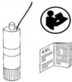
Read these instructions before installing the pump. Save them for future reference.
The DRAINEX models are used for the drainage of sewage water with particles in suspension, septic tanks, etc. Passage of particles in the DRAINEX 400/500 models = 40mm (MAX) and in the DRAINEX 600 models = 65mm (MAX).
The maximum water temperature is 40^ C.
All pumps have been manufactured in top quality material, submitted to strict hydraulic and electric controls.
Correct pump operation is assured providing the instructions on electrical connection, installation and use are strictly adhered to.
Failure to adhere to the instructions can result in premature failure of the pump and voiding of the warranty.
The pump cannot be used in a swimming-pool while there are people bathing.
Do not put your hand or any object into the suction or discharge mouth, since the rotating impeller could cause serious injury or damage.
2. APPLICATION
- Equipment to transfer water containing suspended particles.
- Pumps suitable for extracting drainage and waste water; with filter for solids measuring 40mm and 65 mm.
3. SAFETY
The pump must only be installed in pits by qualified personnel in strict compliance with health and safety regulations in force.
Pit work must be carried out in accordance with local regulations.
4. HANDLING
The pumps are supplied suitably packaged to prevent damage in transit. Before unpacking, check that the packaging has not been damaged or de-formed,
Lift and handle the product with care and with the right tools.
5. INSTALLATION
5.1. Fixing and transport
- Transportable option
- Stationary option
In both cases, the necessary accessories can be supplied separately with their assembly instruct- ions.
For the transportable option, the following are supplied: a chain, stainless steel bases, discharge elbow and screws to fix the latter.
For the stationary option, the following are supplied: a pump fixing accessory, a stationary accessory, a base for two 1" tubes, a joint and all necessary nuts and bolts. See (Fig. 3)
Always lift the pump using the handle.
The pump must always be totally submerged which will provide it with the necessary cooling.
Ensure there is enough space for the free operation of the float switch (fig.3).
The pump must never be supported by the electric cable or the discharge line (fig.3).
5.2. Discharge pipe assembly
In cases in which the discharge run is lengthy or sinuous, we recommend using lines with a larger diameter than the discharge mouth, to avoid head loss due to friction as much as possible and to obtain the best hydraulic performance possible.
Install a check valve to the outlet of the pump and you will prevent pipe from emptying each time pump stops.
The check valve must permit the passage of solids. Ensure that the pipe is not bent and that is correctly secured to the outlet connection because, in addition to preventing the desired flow, proper pump operation will be hindered.
5.3. Electrical connection

The electrical installation must have an effective earth and comply with the national regulations in force.
The protection of the system will be based on a differential switch ( fn = 30mA ) in addition to a multi-pole isolator with a minimum 3 mm contact openings,
Pumps assembled with a starting control box or fitted with a capacitor are supplied ready for operation.
In the case of three-phase pumps the user must provide the protection system.
All pumps must be connected to a control panel fitted with a motor protector. ESPA control panels are built in. The panel comes with the operating instructions and technical information.
5.4. Pre-start checks
The fitter must use a liquid level detection system to ensure that the pump remains submerged at all times.
Pumps are supplied with thermal protectors in their windings. The latter must be connected to a protective switch so that the pump is disconnected before the winding reaches the maximum permitted temperature. Regulations do not permit automatic reconnection, so the control panel must also be equipped with a system to prevent automatic resetting.
ESPA control panels are equipped with all the safety devices mentioned.
See connections diagram (Fig. 2).
THIS PUMP MUST NEVER BE DRY RUN.
5.5. Checks prior to initial start-up

ATTENTION. Check that the mains voltage and frequency coincide with those shown on the nameplate.
The pump must work in a fully submerged position to achieve optimal cooling. See (Fig. 4)
THE PUMP MUST NEVER OPERATE WITHOUT WATER.
6. STARTING
If there is a line valve, open it completely.
Connect the electrical panel plug into a socket. If there is an appropriate level of water, the motor will immediately start up.
Check that the absorbed current is the same as marked on the name plate.
If the motor does not start or no water flows at the end of the line, try to find the anomaly using the troubleshooting guide in point 8.
In the case of three-phase pumps check that the turning direction corresponds to the direction marked by the arrow situated in the suction cone. (fig. 4)

Contact with the rotating impeller may cause serious injury.
7. MAINTENANCE
7.1. General indications

Disconnect the pump from the mains before performing any operation whatsoever.
Under normal conditions these pumps require no special or planned maintenance.

During frosty periods, remember to drain the line.
If the pump is not going to be operated for a long period of time, it is recommended to remove the tank, clean it and store it in a dry, well ventilated place.
To unclog or clean the impeller, it is only necessary to raise the suction cone. To do this, unscrew the screws that fasten the legs. The cover assembly must come off as a whole (fig.4).

ATTENTION: In the event of faults or damage occurring to the pump, repairs should only be carried out by an authorised service agent.
The Official Technical Services list is in www.espa.com.
7.2. Maintenance / inspection
Maintenance must be carried out exclusively by a specialist.
Annual checks:
Check the power consumption, comparing it to the plate showing the characteristics of the pump.
Bearings and lubrication:
The bearings are supplied greased. They do not require subsequent lubrication.
To ensure that the bearings work properly, check whether the axis produces noise or does not rotate smoothly.
Wire inlet and suspension chain:
Visually check that the wire inlet is sealed and that the wire is not bent or pinched.
Check that the chain is secured properly and that it is not damaged.
Cleaning the runner:
To unblock or clean the runner, you only need to lift the suction base. To do so, loosen the fixing screws (as shown in (Fig. 4)).
Changing the oil:
The oil that lubricates the locks while the pump operates under normal conditions should be changed after 3000 h of operation or once a year.
To empty it, dismantle the runner and loosen the T screw shown in (Fig. 4); and/or remove the lock.
Remember that once the rotating part of the lock has been loosened, the oil may leak between the friction areas.
To aid extraction of the runner, once you have removed the fixing screw you can screw in a M10 screw in the thread in the centre of the runner fitted for this purpose.
The oil used is a white oil of mineral origin with medicinal quality. The quantity is 0.7 l.
When changing the oil, use one with similar characteristics that fulfils regional regulations.
If you dismantle the mechanical locks, you are advised to replace them and change the oil.
8. DISPOSING OF THE PRODUCT
When the pump is eventually disposed of, please note that it contains no toxic or polluting material. All main components are material identified to allow selective disposal.
This product or parts of it must be disposed of in an environmentally sound way, use the waste collection service. If this is not possible, contact the nearest ESPA service workshop.
- PLATE SHOWING CHARACTERISTICS
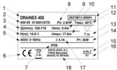
text_image
DRAINEX 400 400 50 013681/STD Q(l/min): 166-716 Hmin: 0.4m H(m): 14,5-1 Hmax: 17.5m 400V 3~50Hz I: 4.1A P1: 2kW IPX8 ESPA 2025, S.L. 17820 Banyoles (MADE IN SPAIN) Is.KLF S1 11 12 13 14 15 16 7 18 17DESCRIPTION
| 1 | Item reference |
| 2 | Voltage + frequency + item specifications |
| 3 | Flow |
| 4 | Pressure |
| 5 | Nominal voltage, no. stages, alternate current symbol and frequency |
| 6 | EC mark |
| 7 | Humidity protection level |
| 8 | Motor max. nominal output (P2) |
| 9 | Minimum working pressure |
| 10 | Maximum pressure |
| 11 | Year and week of manufacture + Pump serial number |
| 12 | Max. liquid temperature |
| 13 | Max. immersed depth |
| 14 | Electric pump unit absorbed power (P1) |
| 15 | Designated motor insulation |
| 16 | Continuous operation symbol |
| 17 | Maximum nominal intensity at nominal voltage |
| 18 | Name and address of vendor responsible for the product |
10. POSSIBLE FAULTS, CAUSES AND SOLUTIONS
1) The pump does not start.
2) Pump runs but there is no flow.
3) Pump stops automatically.
4) Pump does not deliver rated capacity.
| 1 | 2 | 3 | 4 | POSSIBLE PROBLEM | SOLUTIONS |
| X | Lack of electricity | Replace fuses or switch RCCB (30mA) | |||
| X | X | Improper thermal protection | Switch thermal protector or check that voltage is correct | ||
| X | Float switch disconnected | Wait for water level to be back to adequate level | |||
| X | X | Wet end blocked | Call Service Engineer | ||
| X | Blocked float switch | Check the free operation of the float switch | |||
| X | Disconnected discharge pipe | Connect it and fix the discharge pipe correctly | |||
| X | Air trapped at the pump body | Move the pump laterally to empty the air | |||
| X | Check valve assembled way round | Assemble the valve correctly | |||
| X | Pump partially covered of water | Submerge the pump or wait to have the suitable level | |||
| X | X | Inlet filter obstructed | Clean the suction filter | ||
| X | Total manometric head higher than expected | Check the geometric head and loss of head | |||
| X | Impeller worn | Contact a Service Engineer | |||
| X | Deteriorated discharge pipe | Replace it by a new one |
11. TECHNICAL DATA
Liquid temperature... 4°C - 40°C
Ambient temperature: 0°C - 40°C
Storage temperature: -10°C - 50°C
Ambient relative humidity, max.: 95%
Motor class I.
Other data see Figure 1.
8. AFVOEREN VAN HET PRODUCT
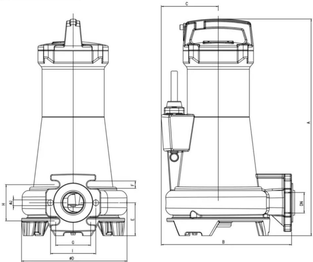
EN List of main components
text_image
Technical cross-sectional diagram of a mechanical device with numbered components for identification.| ES | EN | FR | DE | IT | |
| 1 | Carcasa del motor | Motor casing | Carcasse de moteur | Motorgehäuse | Carcassa del motore |
| 2 | Rodamiento | Bearing | Roulement | Wälzlager | Cuscinetto |
| 3 | Cuerpo bomba | Pump casing | Corps de pompe | Pumpengehäuse | Corpo della pompa |
| 4 | Cierre parte motor | Motor system lock | Fermeture bloc moteur | Verschluss motorbereich | Chiusura parte motora |
| 5 | Cierre parte hidráulica | Hidraulic system lock | Fermeture partie hydraulique | Verschluss hydraulischer bereich | Chiusura parte idraulica |
| 6 | Toma equipotencial | Equipotential connection | Prise equipotentielle | Aquipotentialer anschluss | Presa equipotenziale |
| 7 | Eje motor | Motor shaft | Arbre de moteur | Motorwelle | Albero del motore |
| 8 | Cable | Cable | Câble | Kabel | Cavo |
| 9 | Sensor humedad (*) | Humidity sensor (*) | Senseur d'humidité (*) | Feuchtigkeitssensor (*) | Sensore di umidità (*) |
| 10 | Rodete | Impeller | Roue | Laufrad | Girante |
| 11 | Tapa aspiración | Suction cover | Fond d'aspiration | Saugdekel | Coperchio, lato aspirante |
| PT | NL | RU | AR | CH | |
| 1 | Carcasa motor | Motorhuis | Корпус электродвигателя | المنازن التحركة | 馬達外殼 |
| 2 | Rolamento | Lager | Подшипник | المchool | 軸頸 |
| 3 | Corpo de pompa | Pompbehuizing | Корпус гидравлической части | جسم المضخة | 泵體 |
| 4 | Fecho parte do motor | Afdichting/deksel motorgedeelite | закрыть моторную часть | إغلاق الجزء الحركي | 馬達部分關閉 |
| 5 | Fecho parte hidraulica | Afdichting/deksel hydraulisch gedeelite | закрувающая гидравлическая часть | إغلاق الجزء الهیدروليكي | 液壓零件關閉 |
| 6 | Ligaçao equipotencial | Equipotentiële aansluiting | Экви потенциальная розетка | مGPS متساوي الجهد | 等電位分流 |
| 7 | Veio de motor | Motoras | Вал | عمود المحرك | 電機軸 |
| 8 | Cabo | Kabel | Кабельный ввод | ال KBAIL | 電纖 |
| 9 | Sensor humidade (*) | Vocht sensor (*) | датчик влажности (*) | (*) جهاز استثماعار ERPロBUPE ( | 濕度感測器 (*) |
| 10 | Impulsor | Impeller | Рабочее колесо | الدافعة | 葉輪 |
| 11 | Tapa aspiração | zuigdeksel | Крышка гидравлической части | خطاء الشفط | 吸盤 |
Fig.1 / Abb.1 / Afb.1 / Puc.1
| 50 Hz | Q max. [l/min] | H max. [m] | A 3~400V | P1 [kW] | IP | η(%) | A [mm] | B [mm] | C [mm] | D [mm] | DN | E [mm] | F [mm] | G [mm] | H [mm] | I [mm] | J [mm] | [kg] |
| DRAINEX 400 | 716 | 17,5 | 4,1 | 2 | X8 | 43 | 488 | 319 | 130 | 251 | 50 | 75 | 19 | 86 | 86 | 110 | 14 | 45 |
| DRAINEX 401 | 783 | 20,5 | 4,7 | 2,5 | X8 | 47 | 488 | 319 | 130 | 251 | 50 | 75 | 19 | 86 | 86 | 110 | 14 | 45 |
| DRAINEX 402 | 865 | 23,5 | 5,5 | 3,2 | X8 | 48 | 488 | 319 | 130 | 251 | 50 | 75 | 19 | 86 | 86 | 110 | 14 | 45 |
| DRAINEX 500 | 850 | 25 | 7,2 | 4,2 | X8 | 47 | 526 | 319 | 139 | 256 | 50 | 80 | 19 | 86 | 86 | 110 | 14 | 55 |
| DRAINEX 501 | 870 | 29 | 8,3 | 5 | X8 | 48,5 | 526 | 319 | 139 | 256 | 50 | 80 | 19 | 86 | 86 | 110 | 14 | 55 |
| DRAINEX 502 | 890 | 33 | 8,7 | 5,3 | X8 | 48 | 526 | 319 | 139 | 256 | 50 | 80 | 19 | 86 | 86 | 110 | 14 | 55 |
| DRAINEX 600 | 1050 | 16 | 5,7 | 3 | X8 | 48,5 | 567 | 348 | 139 | 254 | 65 | 87 | 19 | 110 | 110 | - | - | 60 |
| DRAINEX 601 | 1200 | 19 | 6,8 | 3,9 | X8 | 52 | 567 | 348 | 139 | 254 | 65 | 87 | 19 | 110 | 110 | - | - | 60 |
| DRAINEX 602 | 1310 | 22 | 8,1 | 4,8 | X8 | 52 | 567 | 348 | 139 | 254 | 65 | 87 | 19 | 110 | 110 | - | - | 60 |
Fig.2 / Abb.2 / Afb.2 / Рис.2
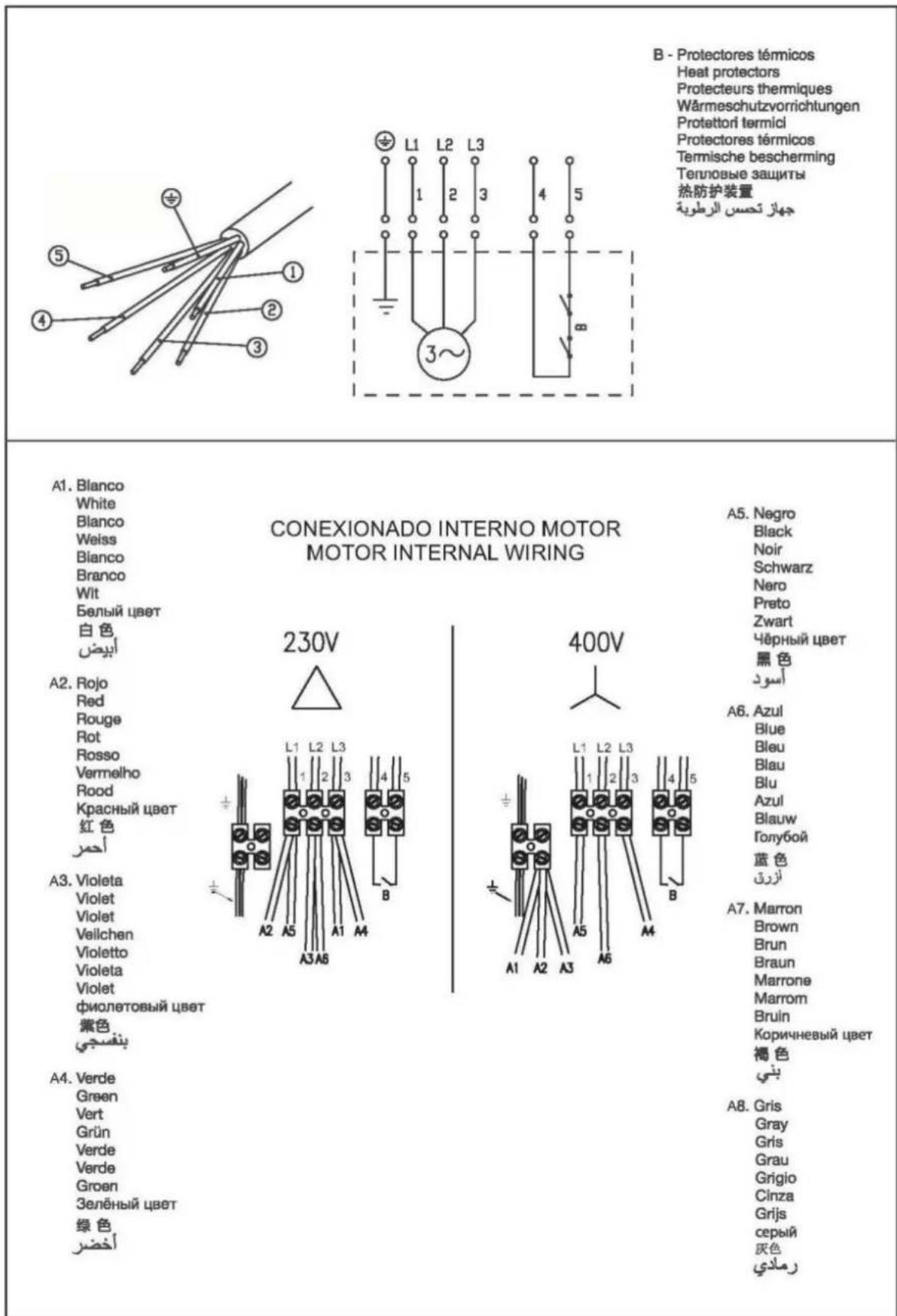
text_image
B - Protectores térmicos Heat protectors Protecteurs thermiques Wärmeschutzvorrichtungen Protettori termici Protectores térmicos Termische bescherming Тепловые защиты 热防护装置 JEHAZ تحسن الرطوية A1. Blanco White Blanco Weiss Blanco Branco Wit Белый цвет 白色 ابيض A2. Rojo Red Rouge Rot Rosso Vermelho Rood Красный цвет 红色 ACHM A3. Violeta Violet Violet Veilchen Violetto Violeta Violet фиолетовый цвет 紫色 بنفصجي A4. Verde Green Vert Grün Verde Verde Groen Зелёный цвет 绿色 أخضر CONEXIONADO INTERNO MOTOR MOTOR INTERNAL WIRING A5. Negro Black Noir Schwarz Nero Preto Zwart Чёрный цвет 黑色 Аسود A6. Azul Blue Bleu Blau Blu Azul Blauw Голубой 蓝色 ازرق A7. Marron Brown Brun Braun Marrone Marrom Bruin Коричневый цвет 褐色 بني A8. Gris Gray Gris Grau Grigio Cinza Grijs серый 灰色 رملاديnatural_image
Technical line drawings of two industrial pump assemblies, one with chain and hook components, the other with a vertical support structure (no text or labels)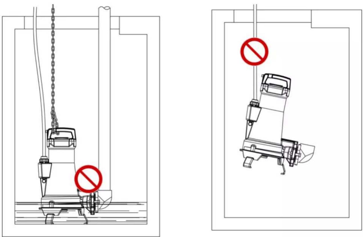
text_image
Technical diagram showing two mechanical device configurations with prohibition signs, one marked with a red circle and the other with a red circle.natural_image
Technical line drawing of a mechanical component with a black arrow indicating rotational motion (no text or symbols present)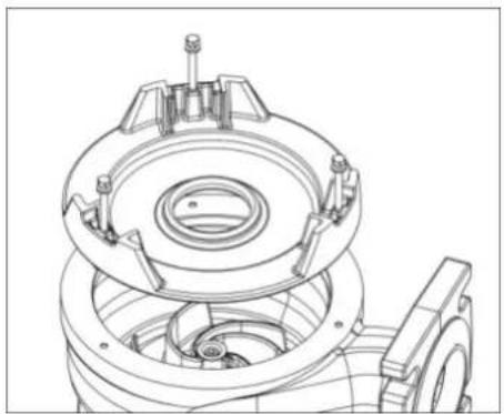
natural_image
Technical line drawing of a mechanical assembly with gears and housing (no text or symbols)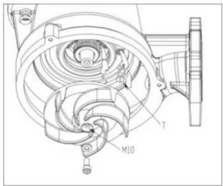
text_image
M10 TFig. 5 / Abb.5 / Afb.5 / Рис.5
 |  |  |  |
| A | B | C | D |
 |  |  |  |
| E | F | G | H |
 |  |  |  |
| I | J | K | L |
NOTAS
ESPA 2025, S.L.
Ctra. de Mieres, s/n - 17820 BANYOLES
GIRONA - SPAIN
www.espa.com