Drainex 100 - Pump ESPA - Free user manual and instructions
Find the device manual for free Drainex 100 ESPA in PDF.
| Product Type | Submersible drainage pump |
| Brand | ESPA |
| Model | Drainex 100 |
| Application | Lifting of water with suspended particles, septic tanks, emptying of tanks or pools |
| Maximum liquid temperature | 35 °C |
| Solid particle passage | 35 mm |
| Supply voltage | 230 V single-phase |
| Frequency | 50 Hz |
| Absorbed power (P1) | 0.75 kW |
| Rated current | 3.4 A |
| Capacitor | 12 µF - 450 V |
| Protection rating | IP68 |
| Maximum immersion depth | 8.5 m |
| Flow rate | 25 to 250 L/min |
| Manometric head | 2 to 7 m |
| Maximum pressure | 7 m |
| Motor insulation class | Is.KLF |
| Operating mode | Continuous (S1) |
| Ambient temperature | 0 °C to 40 °C |
| Storage temperature | -10 °C to 50 °C |
| Maximum ambient humidity | 95 % |
| Maintenance | No maintenance required under normal conditions; clean and store dry if inactive for long periods |
| Safety | Use a 30 mA residual current device and earthing; never run dry |
| Technical service | Interventions reserved for ESPA approved technical service (www.espa.com) |
Frequently Asked Questions - Drainex 100 ESPA
User questions about Drainex 100 ESPA
0 question about this device. Answer the ones you know or ask your own.
Ask a new question about this device
Download the instructions for your Pump in PDF format for free! Find your manual Drainex 100 - ESPA and take your electronic device back in hand. On this page are published all the documents necessary for the use of your device. Drainex 100 by ESPA.
USER MANUAL Drainex 100 ESPA
DRAIN 100M DRAINEX 100M
natural_image
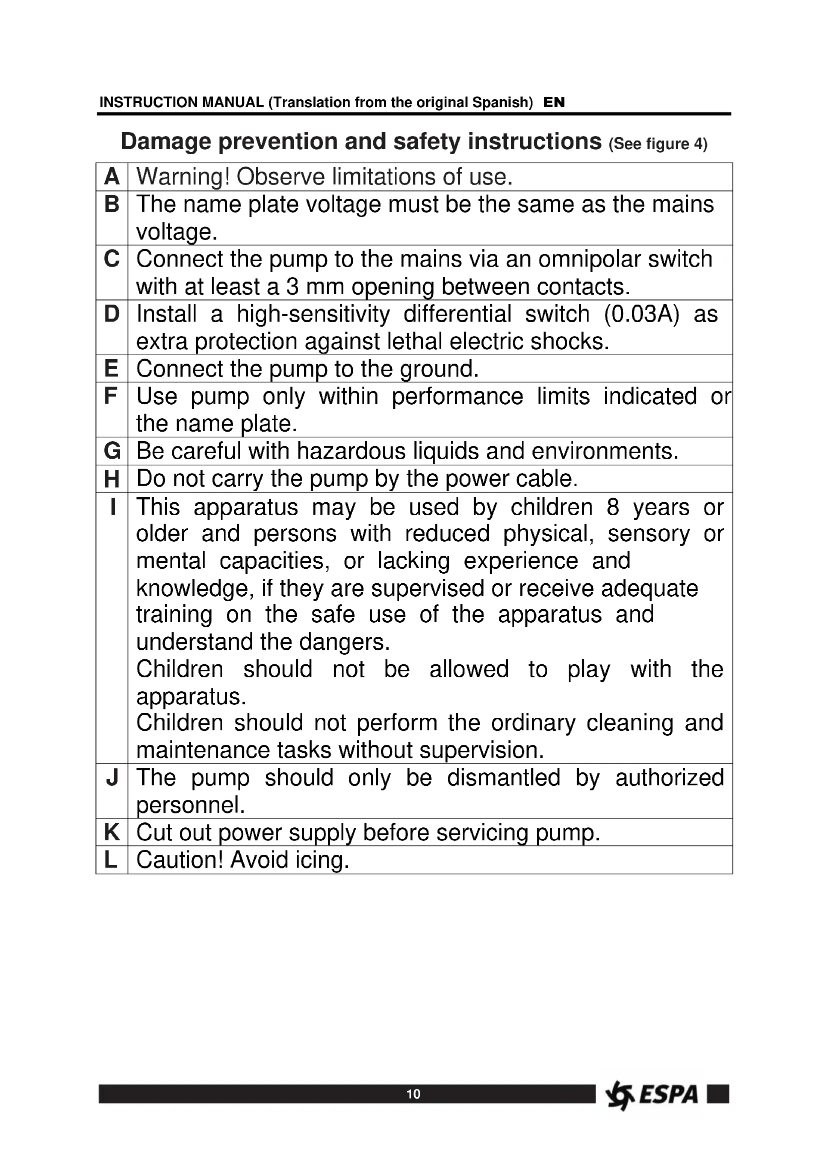
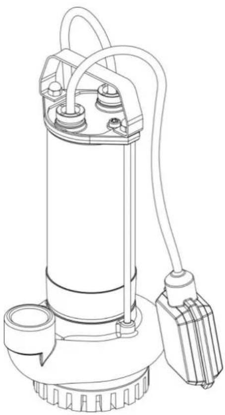
Line drawing of a cylindrical industrial water pump with attached tubing and base (no text or symbols)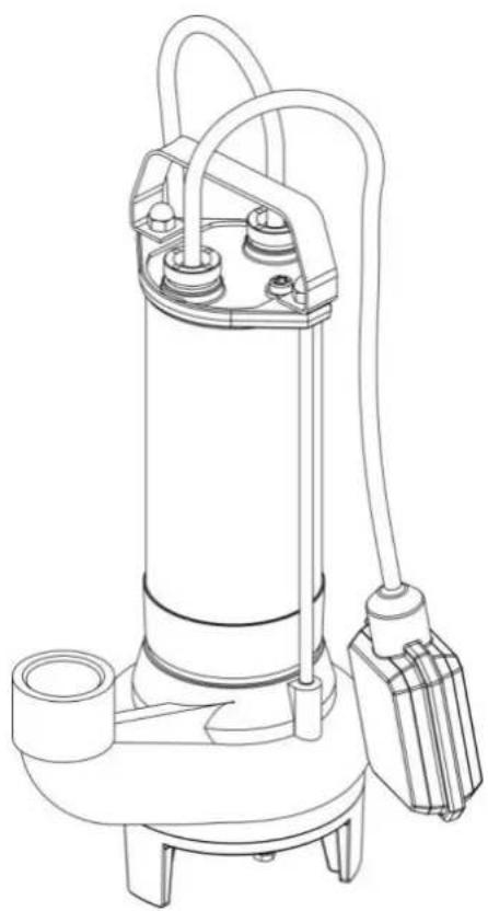
natural_image
Technical line drawing of a cylindrical industrial water pump with attached tubing and control panel (no text or symbols)ES Manual de instrucciones .... 6
(Original)
EN Instruction manual.... 10
(Translation from the original Spanish)
FR Manuel d'instructions 14
(Traduction de l'original en espagnol)
DE Gebrauchsanweisung 18
(Übersetzungausdem Original in Spanisch)
IT Manuale d'istruzioni 22
(Traduzione dall'originale spagnolo)
PT Manual de instruções.... 26
(Tradução do original em espanhol)
NL Handleiding 30
(vertaling van de oorspronkelijke Spaanse)
RU Руководство по эксплуатации 34
(Перевод с оригинального испанского)
ZH 使用说明 38
(从原来的西班牙语翻译)
AR
...... 40
)
EN: EVIDENCE OF CONFORMITY
We declare, under our responsibility, that the products in this manual comply with the following directives and standards:
- Directive 2006/42/EC (Machine Security): Standard EN 809 and EN 60204-1
- Directive EMC 2014/30/EU (Electromagnetic compatibility): Standard EN 61000-6-1 y EN 61000-6-3
- Directive 2014/35/EU (Low voltage): Standard EN 60335-1, EN 60335-2-41
- Directive 2009/125/EC (ecological design): Regulation (EU) 2019/1781 electrical motors and variable speed drives. Standard EN 60034-30.
- Directive 2012/19/EU (on waste electrical and electronic equipment (WEEE)): Standard EN 50419:2006 about marking of electrical and electronic equipment.
- Directive 2011/65/UE (Restriction of hazardous substances): Standard EN 50581
FR : DECLARATION DE CONFORMITÉ
- Directiva 2014/30/UE (EMC): Norme EN 61000-6-1 e a EN 61000-6-3
EVIDENCE OF CONFORMITY
We declare, under our responsibility, that the products in this manual comply with the following directives and standards:
- Supply of Machinery (Safety) Regulations 2008: Standard BS 809 and BS 60204-1
- Electromagnetic Compatibility Regulations 2016: Standard BS 61000-6-1 and BS 61000-6-3.
- Electrical Equipment (Safety) Regulations 2016: Standard BS 60335-1 and BS 60335-2-41.
- The Ecodesign for Energy-Related Products and Energy Information (Amendment) (EU Exit) Regulations 2019: Standard BS 60034-30.
- The Restriction of the Use of Certain Hazardous Substances in Electrical and Electronic Equipment Regulations 2012. Standard BS 50581.
Banyoles, January 14th 2021

Josep Unyó (Technical Manager)
ESPA 2025, SL
Ctra. de Mieres, s/n – 17820 Banyoles
Girona - Spain
Damage prevention and safety instructions (See figure 4)
| A | Warning! Observe limitations of use. |
| B | The name plate voltage must be the same as the mains voltage. |
| C | Connect the pump to the mains via an omnipolar switch with at least a 3 mm opening between contacts. |
| D | Install a high-sensitivity differential switch (0.03A) as extra protection against lethal electric shocks. |
| E | Connect the pump to the ground. |
| F | Use pump only within performance limits indicated or the name plate. |
| G | Be careful with hazardous liquids and environments. |
| H | Do not carry the pump by the power cable. |
| I | This apparatus may be used by children 8 years or older and persons with reduced physical, sensory or mental capacities, or lacking experience and knowledge, if they are supervised or receive adequate training on the safe use of the apparatus and understand the dangers.Children should not be allowed to play with the apparatus.Children should not perform the ordinary cleaning and maintenance tasks without supervision. |
| J | The pump should only be dismantled by authorized personnel. |
| K | Cut out power supply before servicing pump. |
| L | Caution! Avoid icing. |
Contents
Safety precautions....10
-
General information....11
-
Handling....11
-
Installation ....11
3.1. Fixing....11
3.2. Discharge pipe assembly .....11
3.3. Electrical connection .....11
3.4. Pre-start checks .....12
- Starting 12
- Maintenance....12
- Disposing of the product....12
- Nameplate 12
- Possible faults, causes and solutions....13
- Technical data 13
- List of main components....42
- Illustrations....43
Safety precautions
This symbol together with one of the following words “Danger” or “Warning” indicates the risk level deriving from failure to observe the prescribed safety precautions:

DANGER
risk of electric shock

DANGER

WARNING

Warns that failure to observe the pre cautions involves a risk of electric shock.
Warns that failure to observe the pre cautions involves a risk of damage to persons and/or things.
Warns that failure to observe the pre cautions involves the risk of damaging the pump and/or the facility.
Do not put your hand or any object into the suction or discharge mouth, since the rotating impeller could cause serious injury or damage.
1. GENERAL INFORMATION
Please observe the following instructions to achieve the best pump performance possible and a trouble free installation.

Read these instructions before installing the pump. Save them for future reference.
DRAIN series have been designed for the drainage of infiltration water, empty water tanks or swimming pools. DRAINEX series are used for the drainage of sewage water with particles in suspension, septic tanks, etc. The maximum water temperature is 35^ C. Passage of particles up to 35mm.
All pumps have been manufactured in top quality material, submitted to strict hydraulic and electric controls.

Correct pump operation is assured providing the instructions on electrical connection, installation and use are strictly adhered to.

Failure to adhere to the instructions can result in premature failure of the pump and voiding of the warranty.

The pump cannot be used in a swimming-pool while there are people bathing.
2. HANDLING
The pumps are supplied suitably packaged to prevent damage in transit. Before unpacking, check that the packaging has not been damaged or deformed,

Lift and handle the product with care and with the right tools.
3. INSTALLATION
3.1. Fixing

The pump must always be totally submerged which will provide it with the necessary cooling. If there is a lot of dirt at the bottom of the water tank, and you are using a DRAIN pump, it is important to install the pump at least 5cm away from the bottom to avoid dirt blocking the wet end.
Ensure there is enough space for the free operation of the float switch (fig.3).

The pump must never be supported by the electric cable or the discharge line, if it is necessary that the pump does not touch the bottom, suspend it by a plastic cable fixed to the transport handle.
3.2. Discharge pipe assembly
In cases in which the discharge run is lengthy or sinuous, we recommend using lines with a larger diameter than the discharge mouth, to avoid head loss due to friction as much as possible and to obtain the best hydraulic performance possible.
Install a check valve to the outlet of the pump and you will prevent pipe from emptying each time pump stops.
Ensure that the pipe is not bent and that is correctly secured to the outlet connection because, in addition to preventing the desired flow, proper pump operation will be hindered.
3.3. Electrical connection

The electrical installation must have an effective earth and comply with the national regulations in force.
The protection of the system will be based on a differential switch ( fn = 30mA ) in addition to a multi-pole isolator with a minimum 3mm contact openings,
Pumps assembled with a starting control box or fitted with a capacitor are supplied ready for operation.
In the case of three-phase pumps the user must provide the protection system.
3.4. Pre-start checks

Ensure the voltage and frequency of the supply corresponds to the values indicated on the electrical data label.
Ensure that the pump is submerged as shown in Fig.3.
THIS PUMP MUST NEVER BE DRY RUN.
NEVER MODIFY THE FLOAT SWITCH POSITION, WHICH IS ADJUSTED BY THE MANUFACTURER.
4. STARTING
If there is a line valve, open it completely.
Connect the electrical panel plug into a socket. If there is an appropriate level of water, the motor will immediately start up.
Check that the absorbed current is the same as marked on the nameplate.
If the motor does not start or no water flows at the end of the line, try to find the anomaly using the troubleshooting guide in point 8.
In the case of three-phase pumps check that the turning direction corresponds to the direction marked by the arrow situated in the suction cone.
5. MAINTENANCE
Under normal conditions these pumps require no special or planned maintenance.

During frosty periods, remember to drain the line.
If the pump is not going to be operated for a long period of time, it is recommended to remove the tank, clean it and store it in a dry, well ventilated place.
ATTENTION: In the event of faults or damage occurring to the pump, repairs or electric cable replacement should only be carried out by an authorised service agent.
The Official Technical Services list is in www.espa.com.
6. DISPOSING OF THE PRODUCT
When the pump is eventually disposed of, please note that it contains no toxic or polluting material. All main components are material identified to allow selective disposal.
This product or parts of it must be disposed of in an environmentally sound way, use the waste collection service. If this is not possible, contact the nearest ESPA service workshop.
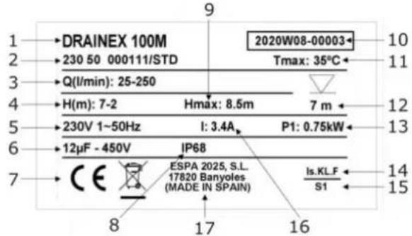
- PLATE SHOWING CHARACTERISTICS
text_image
DRAINEX 100M 230 50 000111/STD Q(l/min): 25-250 H(m): 7-2 230V 1~50Hz 12µF - 450V IP68 ESPA 2025, S.L. 17820 Banyoles (MADE IN SPAIN) 2020W08-00003 Tmax: 35°C Hmax: 8.5m I: 3.4A P1: 0.75kW Is.KL.F S1 10 11 12 13 14 15 9 17 16 8DESCRIPTION
| 1 | Item reference |
| 2 | Voltage + frequency + item specifications |
| 3 | Flow |
| 4 | Pressure |
| 5 | Nominal voltage, no. stages, alternate current symbol and frequency |
| 6 | Capacitor (Single-phase model) |
| 7 | EC mark |
| 8 | Humidity protection level |
| 9 | Maximum pressure |
| 10 | Year and week of manufacture + Pump serial number |
| 11 | Max. liquid temperature |
| 12 | Max. immersed depth |
| 13 | Electric pump unit absorbed power (P1) |
| 14 | Designated motor insulation |
| 15 | Continuous operation symbol |
| 16 | Maximum nominal intensity at nominal voltage |
| 17 | Name and address of vendor responsible for the product |
8. POSSIBLE FAULTS, CAUSES AND SOLUTIONS
1) The pump does not start.
2) Pump runs but there is no flow.
3) Pump stops automatically.
4) Pump does not deliver rated capacity.
| 1 | 2 | 3 | 4 | POSSIBLE PROBLEM | SOLUTIONS |
| X | Lack of electricity | Replace fuses or switch RCCB (30mA) | |||
| X | X | Improper thermal protection | Switch thermal protector or check that voltage is correct | ||
| X | Float switch disconnected | Wait for water level to be back to adequate level | |||
| X | X | Wet end blocked | Call Service Engineer | ||
| X | Blocked float switch | Check the free operation of the float switch | |||
| X | Disconnected discharge pipe | Connect it and fix the discharge pipe correctly | |||
| X | Air trapped at the pump body | Move the pump laterally to empty the air | |||
| X | Check valve assembled way round | Assemble the valve correctly | |||
| X | Pump partially covered of water | Submerge the pump or wait to have the suitable level | |||
| X | X | Inlet filter obstructed | Clean the suction filter | ||
| X | Total manometric head higher than expected | Check the geometric head and loss of head | |||
| X | Impeller worn | Contact a Service Engineer | |||
| X | Deteriorated discharge pipe | Replace it by a new one |
9. TECHNICAL DATA
Liquid temperature... 4°C - 35°C
Ambient temperature: 0°C - 40°C
Storage temperature: -10°C - 50°C
Ambient relative humidity, max.: 95%
Motor class I.
Other data see Figure 1.
6. AFVOEREN VAN HET PRODUCT
EN List of main components
text_image
Technical cross-sectional diagram of a mechanical device with numbered components for identification.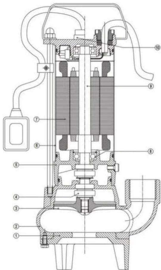
text_image
Technical schematic diagram of a mechanical device with numbered components for identification| ES | EN | FR | DE | IT | |
| 1 | Pie | Foot | Pied | Fub | Piede |
| 2 | Cuerpo bomba | Pump casing | Corps de pompe | Pumpengehäuse | Corpo della pompa |
| 3 | Rodete | Impeller | Roue | Laufrad | Girante |
| 4 | Retén mecánico | Mechanical seal | Garniture mécanique | Gleitringdichtung | Tenuta meccanica |
| 5 | Cuerpo intermedio | Interstage casing | Corps intermédiaire | Zwischengehäuse | Corpo intermedio |
| 6 | Carcasa del motor | Motor casing | Carcasse de moteur | Motorgehäuse | Carcassa del motore |
| 7 | Estátor | Stator | Stator | Stator | Estator |
| 8 | Rodamiento | Bearing | Roulement | Wälzlager | Cuscinetto |
| 9 | Eje motor | Motor shaft | Arbre de moteur | Motorwelle | Albero del motore |
| 10 | Cable | Cable | Câble | Kabel | Cavo |
| PT | NL | RU | ZH | AR | |
| 1 | Pe | Voet | Опора | 脚 | قدم |
| 2 | Corpo de pompa | Pompbehuizing | Корпус насоса | 泵壳 | المضخة علاف |
| 3 | Impulsor | Impeller | Рабочее колесо | 叶轮 | المكرد |
| 4 | Fecho mecânico | Glijringpakking | Механическое уплотнение | 机械密封 | الي ختم |
| 5 | Corpo intermedio | Tussenbehuizing | Масляная камера | 级间套管 | الوسيط الجسم |
| 6 | Carcasa motor | Motorhuis | Корпус двигателя | 马达外壳 | المحرك غلاف |
| 7 | Estator | Stator | Статор | 定了 | الثابت |
| 8 | Rolamento | Lager | Подшипник | 轴承 | تحمل |
| 9 | Veio de motor | Motoras | Вал двигателя | 电机轴 | المحرك رمح |
| 10 | Cabo | Kabel | Кабель | 电缆 | كابل |
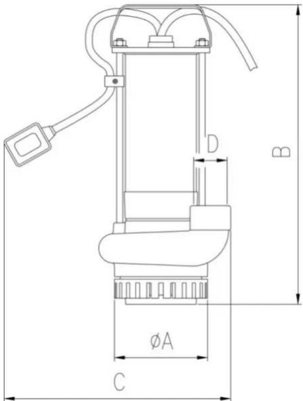
Fig.1 / Abb.1 / Afb.1 / Рис.1
text_image
D B ØA CDRAIN100
text_image
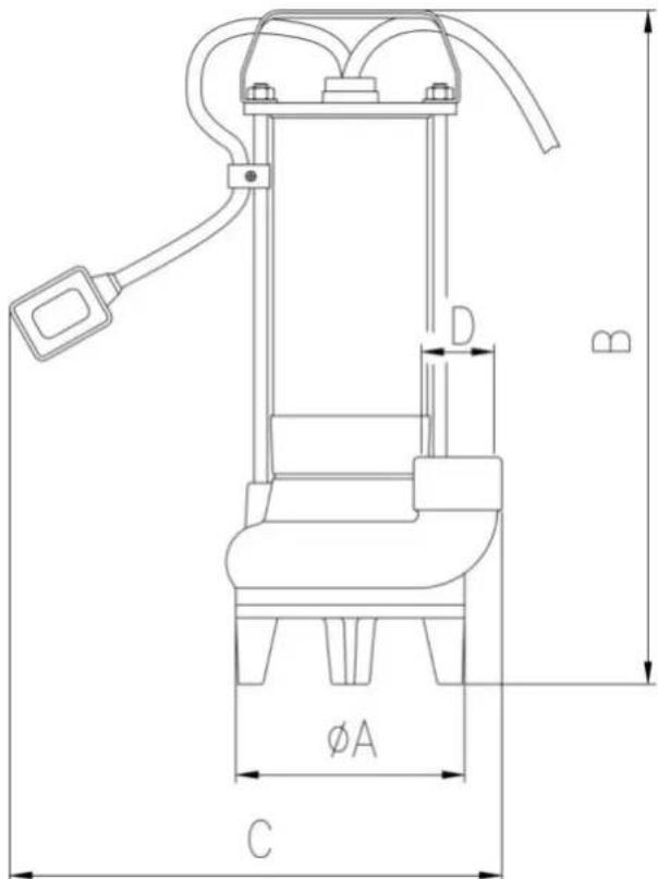
D φA C BDRAINEX100
| 230V 50 Hz | Q max. [l/min] | H max. [m] | A 1~230V | C μF | P1 [kW] | IP | η(%) | A [mm] | B [mm] | C [mm] | D [mm] | ΔT [kg] |
| DRAIN 100M | 300 | 10 | 3.1 | 12 | 0.7 | 68 | 39 | 122 | 392 | 300 | 1 1/4" | 10.5 |
| DRAINEX 100M | 250 | 8.5 | 3.4 | 12 | 0.75 | 68 | 21 | 138 | 407 | 300 | 1 1/4" | 11 |
text_image
① ② ③ E L 230V N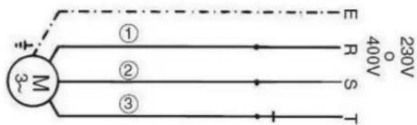
text_image
① ② ③ E R 400V 230V S T| 1. | NEGRO | 2. | AZUL | 3. | MARRON |
| BLACK | BLUE | BROWN | |||
| NOIR | BLEU | MARRON | |||
| SCHWARZ | BLAU | BRAUN | |||
| NERO | AZZURRO | MARRONE | |||
| PRETO | AZUL | CASTANHO | |||
| ZWART | BLAUW | BRUIN | |||
| ЧЕРНЫЙ | ГОЛУБОЙ | КОРИЧНЕВЫЙ | |||
| أسود | ازرق | أسمر | |||
| 黑色 | 蓝色的 | 棕褐色 |
text_image
A B C D E F G H I J K LESPA 2025, S.L.
C/ Mieres, s/n - 17820 BANYOLES
GIRONA – SPAIN
www.espa.com