Draincor - Pump ESPA - Free user manual and instructions
Find the device manual for free Draincor ESPA in PDF.
| Product type | Submersible pump for dirty water |
| Brand | ESPA |
| Model | Draincor |
| Main use | Transfer of water with suspended solids, septic tanks |
| Liquid temperature | 4 °C to 35 °C |
| Ambient temperature | 0 °C to 40 °C |
| Storage temperature | -10 °C to 50 °C |
| Maximum relative humidity | 95 % |
| Motor class | Class I |
| Thermal protection | Built-in (manual reset) |
| Recommended safety device | 30 mA residual current device, grounding |
| Installation type | Submerged, with level float |
| Maintenance | Disconnect before servicing; clean impeller and strainer |
| Solid passage diameter | Up to 45 mm (Draincor 200 model) or 60 mm (Draincor 300 model) - depending on version |
| Impeller alignment | Use a 0.3 mm feeler gauge |
| Compliance | Directives 2006/42/EC, 2014/30/EU, 2014/35/EU, 2011/65/EU |
Frequently Asked Questions - Draincor ESPA
User questions about Draincor ESPA
0 question about this device. Answer the ones you know or ask your own.
Ask a new question about this device
Download the instructions for your Pump in PDF format for free! Find your manual Draincor - ESPA and take your electronic device back in hand. On this page are published all the documents necessary for the use of your device. Draincor by ESPA.
USER MANUAL Draincor ESPA
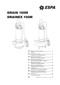
DRAINEX 200/300 DRAINCOR
ES Manual de instrucciones 6 (Original)
EN Instruction manual. 10 (Translation from the original Spanish)
FR Manuel d'instructions 14 (Traduction de l'origine en espagnol)
DE Gebrauchsanweisung 18 (Übersetzungausdem Original in Spanisch)
IT Manuale d'istruzioni 22 (Traduzione dall'originale spagnolo)
PT Manual de instruções 26 (Tradução do original em espanhol)
NL Handleiding 30 (vertaling van de oorspronkelijke Spaanse)
RU RykoBoDCTBO NO 3KcNpyaTALIN 34 (TepeoC opuzuHaBHOO uCnHCKO20)
AR 38
EN: EVIDENCE OF CONFORMITY
We declare, under our responsibility, that the products in this manual comply with the following directives and standards:
- Directive 2006/42/EC (Machine Security): Standard EN 809 and EN 60204-1
- Directive EMC 2014/30/EU (Electromagnetic compatibility) Direttiva 2014/30/UE (Compatibilita elettro-magnetica): Standard EN 61000-6-1 y EN 61000-6-3 Norma EN 61000-6-1 e alla EN 61000-6-3
- Directive 2014/35/EU (Low voltage): Standard EN 60335-1, EN 60335-2-41
- Directive 2011/65/UE (Restriction of hazardous substances): Standard EN 50581.
- Direttiva 2006/42/CE (sicurezza della macchina): Norma EN 809 e alla EN 60204-1
lityDirettiva 2014/30/UE (Compatibilita elettro-magnetica): Norma EN 61000-6-1 e alla EN 61000-6-3 - Direttiva 2014/35/UE (Bassa Tensione): Norma EN 60335-1, EN 60335-2-41
- Direttiva 2011/65/UE (RoHS II): Norma EN 50581.
EVIDENCE OF CONFORMITY
We declare, under our responsibility, that the products in this manual comply with the following directives and standards:
- Supply of Machinery (Safety) Regulations 2008: Standard BS 809 and BS 60204-1
- Electromagnetic Compatibility Regulations 2016: Standard BS 61000-6-1 and BS 61000-6-3.
- Electrical Equipment (Safety) Regulations 2016: Standard BS 60335-1 and BS 60335-2-41.
- The Restriction of the Use of Certain Hazardous Substances in Electrical and Electronic Equipment Regulations 2012. Standard BS 50581.
Banyoles, January 13th 2021

Josep Unyó (Technical Manager)
ESPA 2025, SL
Ctra. de Mieres, s/n - 17820 Banyoles
Girona - Spain
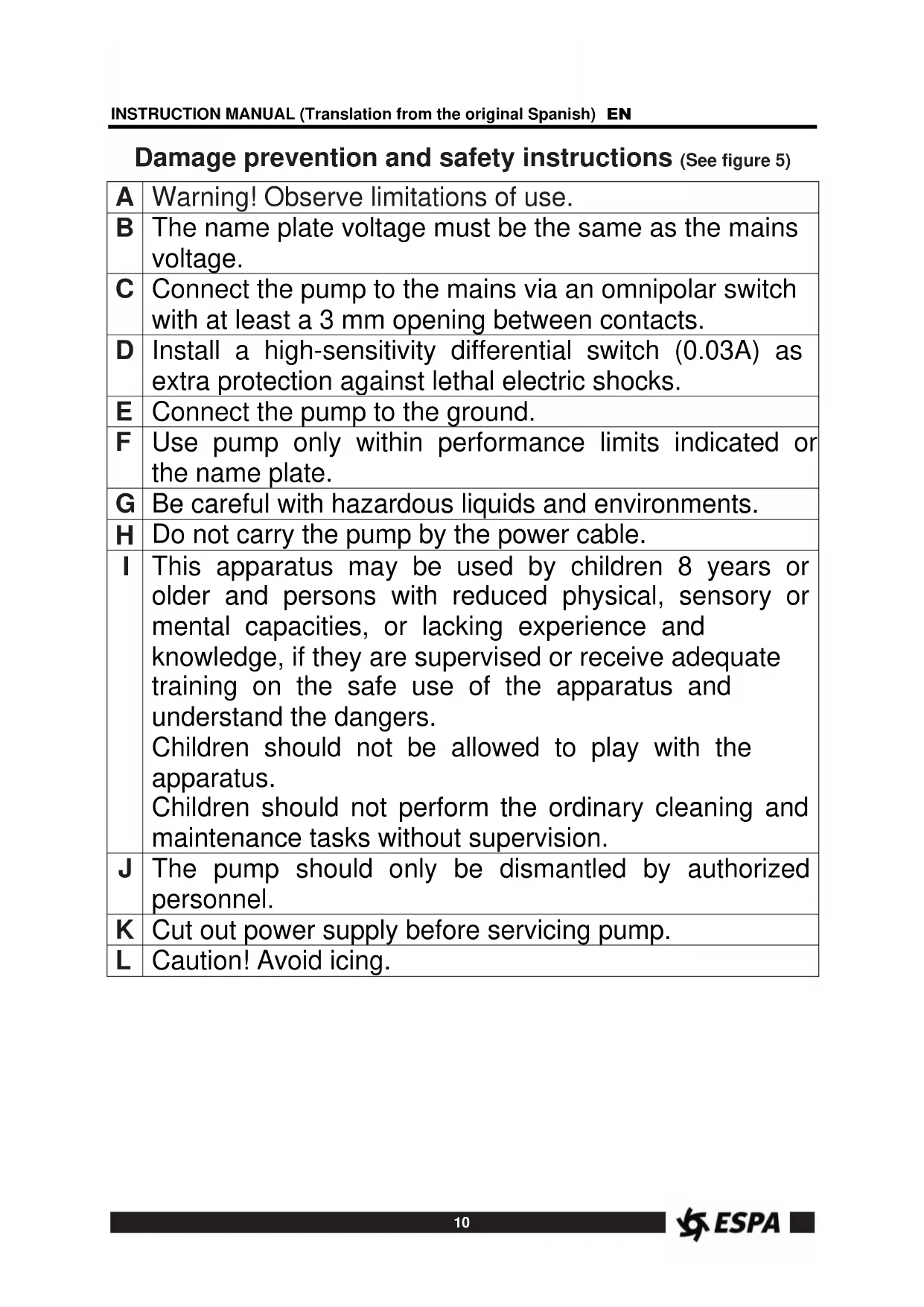
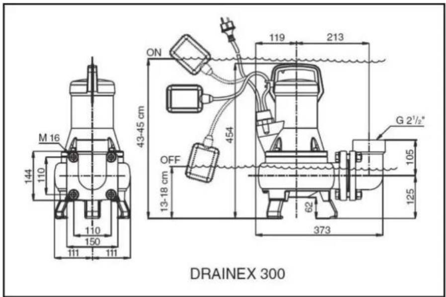
Damage prevention and safety instructions (See figure 5)
| A | Warning! Observe limitations of use. |
| B | The name plate voltage must be the same as the mains voltage. |
| C | Connect the pump to the mains via an omnipolar switch with at least a 3 mm opening between contacts. |
| D | Install a high-sensitivity differential switch (0.03A) as extra protection against lethal electric shocks. |
| E | Connect the pump to the ground. |
| F | Use pump only within performance limits indicated or the name plate. |
| G | Be careful with hazardous liquids and environments. |
| H | Do not carry the pump by the power cable. |
| I | This apparatus may be used by children 8 years or older and persons with reduced physical, sensory or mental capacities, or lacking experience and knowledge, if they are supervised or receive adequate training on the safe use of the apparatus and understand the dangers. Children should not be allowed to play with the apparatus. Children should not perform the ordinary cleaning and maintenance tasks without supervision. |
| J | The pump should only be dismantled by authorized personnel. |
| K | Cut out power supply before servicing pump. |
| L | Caution! Avoid icing. |
Contents
Safety precautions 10
- General information 11
- Handling 11
3.Installation 11
3.1. Fixing 11
3.2. Discharge pipe assembly 11
3.3. Electrical connection 11
3.4. Pre-start checks 11
- Starting 12
- Maintenance 12
6.Disposing of the product. 12 - Nameplate 12
- Possible faults, causes and solutions 13
- Technical data 13
10.List of main components. 40
11.Illustrations. 41
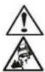
Safety precautions
This symbol together with one of the
following words "Danger" or "Warning" indicates the risk level deriving from failure to observe the prescribed safety precautions:

DANGER
risk of electric shock
Warns that failure to observe the precautions involves a risk of electric shock.

DANGER

WARNING
Warns that failure to observe the precautions involves a risk of damage to persons and/or things.
Warns that failure to observe the pre cautions involves the risk of damaging the pump and/or the facility.
1. GENERAL INFORMATION
Please observe the following instructions to achieve the best pump performance possible and a trouble free installation.

Read these instructions before installing the pump.
Save them for future reference.
The DRAINEX models are used for the drainage of sewage water with particles in suspension, septic tanks, etc. Passage of particles in the DRAINEX 200 models = 45mm MAX and in the DRAINEX 300 models = 60mm MAX).
The maximum water temperature is 35^
All pumps have been manufactured in top quality material, submitted to strict hydraulic and electric controls.

Correct pump operation is assured providing the instructions on electrical connection, installation and use are strictly adhered to.

Failure to adhere to the instructions can result in premature failure of the pump and voiding of the warranty.

The pump cannot be used in a swimmingpool while there are people bathing.

Do not put your hand or any object into the suction or discharge mouth, since the rotating impeller could cause serious injury or damage.
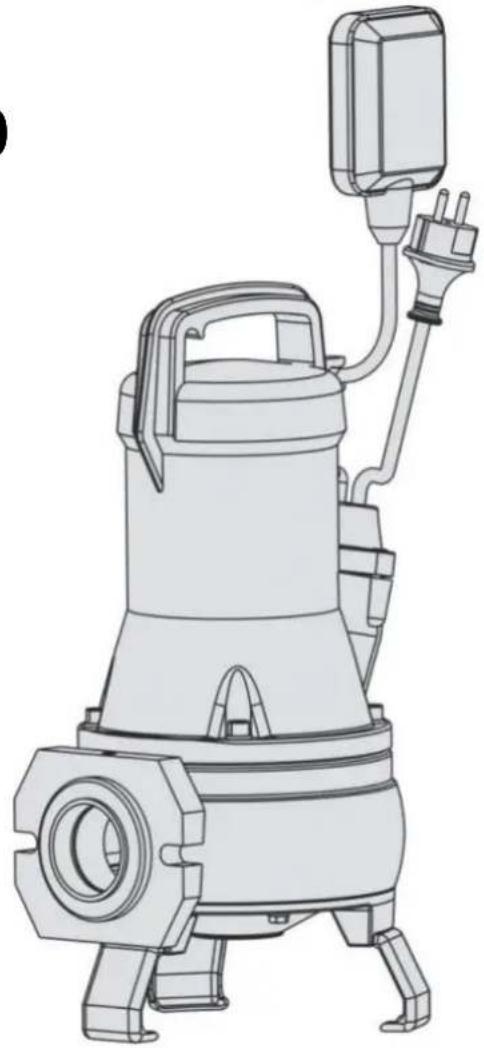
2. HANDLING
The pumps are supplied suitably packaged to prevent damage in transit. Before unpacking, check that the packaging has not been damaged or deformed,

Lift and handle the product with care and with the right tools.
3. INSTALLATION
3.1. Fixing
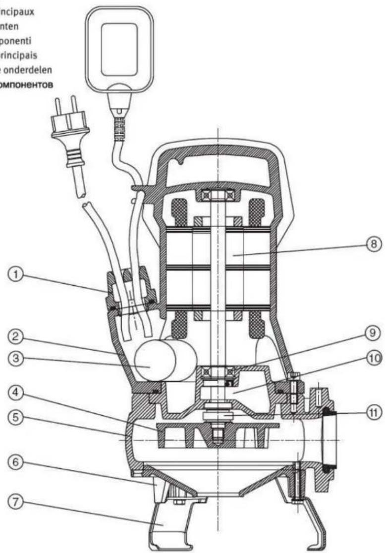
The pump must always be totally submerged which will provide it with the necessary cooling.
Ensure there is enough space for the free operation of the float switch (fig.3).

The pump must never be supported by the electric cable or the discharge line (fig.3).
3.2. Discharge pipe assembly
In cases in which the discharge run is lengthy or sinuous, we recommend using lines with a larger diameter than the discharge mouth, to avoid head loss due to friction as much as possible and to obtain the best hydraulic performance possible.
Install a check valve to the outlet of the pump and you will prevent pipe from emptying each time pump stops. The check valve must permit the passage of solids.
Ensure that the pipe is not bent and that is correctly secured to the outlet connection because, in addition to preventing the desired flow, proper pump operation will be hindered.
3.3. Electrical connection

The electrical installation must have an effective earth and comply with the national regulations in force.
The protection of the system will be based on a differential switch ( fn = 30mA) in addition to a multi-pole isolator with a minimum 3mm contact openings,
Pumps assembled with a starting control box or fitted with a capacitor are supplied ready for operation.
In the case of three-phase pumps the user must provide the protection system.
3.4. Pre-start checks

Ensure the voltage and frequency of the supply corresponds to the values indicated on the electrical data label.
Ensure that the pump is submerged as shown in Fig.3.
THIS PUMP MUST NEVER BE DRY RUN.
4. STARTING
If there is a line valve, open it completely.
Connect the electrical panel plug into a socket. If there is an appropriate level of water, the motor will immediately start up.
Check that the absorbed current is the same as marked on the name plate.
If the motor does not start or no water flows at the end of the line, try to find the anomaly using the troubleshooting guide in point 8.
In the case of three-phase pumps check that the turning direction corresponds to the direction marked by the arrow situated in the suction cone.

Contact with the rotating impeller may cause serious injury.
5. MAINTENANCE

Disconnect the pump from the mains before performing any operation whatsoever.
Under normal conditions these pumps require no special or planned maintenance.

During frosty periods, remember to drain the line.
If the pump is not going to be operated for a long period of time, it is recommended to remove the tank, clean it and store it in a dry, well ventilated place.
To unclog or clean the impeller, it is only necessary to raise the suction cone. To do this, unscrew the screws that fasten the legs. The cover assembly must come off as a whole (fig.4).
On the DRAINCOR, a 0.3mm gauge must be used when refitting to align the turbine with the suction base (fig.4). For correct alignment of the turbine, refer to the screws "A" marked on that drawing.

ATTENTION: In the event of faults or damage occurring to the pump, repairs should only be carried out by an authorised service agent.
The Official Technical Services list is in www.espa.com.
6. DISPOSING OF THE PRODUCT
When the pump is eventually disposed of, please note that it contains no toxic or polluting material. All main components are material identified to allow selective disposal.
This product or parts of it must be disposed of in an environmentally sound way, use the waste collection service. If this is not possible, contact the nearest ESPA service workshop.
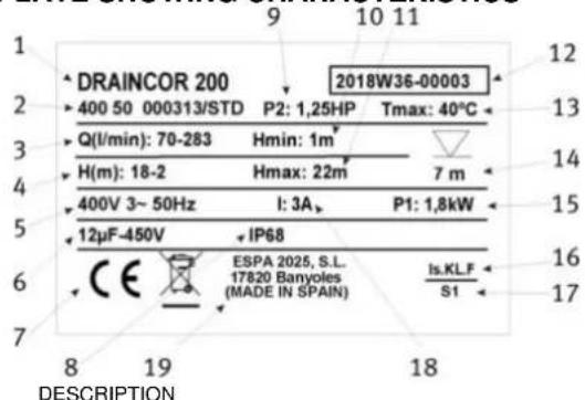
7. PLATE SHOWING CHARACTERISTICS
| 1 | Item reference |
| 2 | Voltage + frequency + item specifications |
| 3 | Flow |
| 4 | Pressure |
| 5 | Nominal voltage, no. stages, alternate current symbol and frequency |
| 6 | Capacitor (Single-phase model) |
| 7 | EC mark |
| 8 | Humidity protection level |
| 9 | Motor max. nominal output (P2) |
| 10 | Minimum working pressure |
| 11 | Maximum pressure |
| 12 | Year and week of manufacture + Pump serial number |
| 13 | Max. liquid temperature |
| 14 | Max. immersed depth |
| 15 | Electric pump unit absorbed power (P1) |
| 16 | Designated motor insulation |
| 17 | Continuous operation symbol |
| 18 | Maximum nominal intensity at nominal voltage |
| 19 | Name and address of vendor responsible for the product |
8. POSSIBLE FAULTS, CAUSES AND SOLUTIONS
1) The pump does not start.
2) Pump runs but there is no flow.
3) Pump stops automatically.
4) Pump does not deliver rated capacity.
| 1 | 2 | 3 | 4 | POSSIBLE PROBLEM | SOLUTIONS |
| X | Lack of electricity | Replace fuses or switch RCCB (30mA) | |||
| X | X | Improper thermal protection | Switch thermal protector or check that voltage is correct | ||
| X | Float switch disconnected | Wait for water level to be back to adequate level | |||
| X | X | Wet end blocked | Call Service Engineer | ||
| X | Blocked float switch | Check the free operation of the float switch | |||
| X | Disconnected discharge pipe | Connect it and fix the discharge pipe correctly | |||
| X | Air trapped at the pump body | Move the pump laterally to empty the air | |||
| X | Check valve assembled way round | Assemble the valve correctly | |||
| X | Pump partially covered of water | Submerge the pump or wait to have the suitable level | |||
| X | X | Inlet filter obstructed | Clean the suction filter | ||
| X | Total manometric head higher than expected | Check the geometric head and loss of head | |||
| X | Impeller worn | Contact a Service Engineer | |||
| X | Deteriorated discharge pipe | Replace it by a new one |
9. TECHNICAL DATA
Liquid temperature. 4^ - 35^
Ambient temperature: 0^ - 40^
Storage temperature: -10°C - 50°C
Ambient relative humidity, max.: 95%
Motor class I.
Other data see Figure 1.
6. AFVOREN VAN HET PRODUCT
7. TEXHnueCKne DAHHbIE
Tempepatya xndkoctn: 4°C - 40°C
Tempepatya okpykaouero Bo3dyxa: ..0°C - 40°C
Tempepatya xpanen: -10°C - 50°C
8. TAPAHINHbIE O83ATEJIbCTBA
HaHacocbIpacnpoctpaHareTcraPANTn
n3ROTOBtEn, cPOK DeNCTBnKOTopoYkA3bIbAeTcB rapaHTnHOM TaHOHe
yCTaHOJIeHHoro 6pa3ca (c DaTbIOKynKn KOHeHbIM NOnb3OBaTeJeM). DokymeHTOM,
NOITBepXdaHOUsm Daty npOdaJx, YBnEeTCRApaHTnHbI TAOHrTOJKeH
6bItb npABINbHO 3ANOHN HPODAuCm
obOpyIDoBaHn. Ero OTCyTCTBne INn
HeNPaBnIbHOe 3ANOHNHeNe MOKeT NOcLyKHTb
npUHNoIOT K3a B rapaHTnHOM 06cLyuKbAHn
obOpyIDoBaHn. IpaHTnHbIe 06a3aTeNbCTBa
BKlIOuAOT B Ce6B BCE npON3BOdCTBeHHbIE
deΦeKtbl INn DEΦeKtbl KOMNJIeKTyOuXn,
NOITBepXdeHHbIe npON3BODtJeM. OnpeDeJIeHne
npUHn BO3HKnHOBeHn HEncnPabHocTeH HAcOCA
npON3BODNTcA BTOPI3OBaHHbIMN CEPBNCbIMN
ueHTpAmN ESPA.
OTHOCHTeBna BnaxHoCTb Bo3dyxa: 95%
Klacc DnrgateJia: I
HbIe daHHbIe: cm. pnc.1.
B clyuae noTBePckDHeHn npOn3BOOCTBeHHORo
6paka nI nDepeKTA KOMNNEKtyUOxN CepBnCHbIM
ZeHTpOM npON3BOOHTCra papaHTnHbI peMOHT nIi
3aMeHa HAcoca. TapaHTnHbIe o6a3aTeNbCTBa He
pacnpoctpaHryOTcHa DepeKtbl, BO3HNKUWe B
pe3yIbTaTe HnpaBnIbHOro 06paueHnE,
He npabnIbHOro 3NeKTPnueCKOrO NOkJIIOueHn, B
cnyuae HapUSeHnna PpaBnI yCTaHOBKn, MOHTaxa,
3KcnIyatau, nPiBedeHHbIX B DaHHOM
pyKOBoODCTBe, a TaKKe Ha KOMNNEKtyUOzne,
NoDBerPkeHHbIe eCTeCTBeHHOMy N3HOcy B
npoucece 3KcnIyatau, a ImEHHo: yNlOTHeHn,
NoDUnNHnKn, KOHeHCaTObpI, UETKN I.T.I.
YcNOBnra rapaHTnHOro 06cnykBaHnra He
npmehraOTcB Cnyuae O6hApyKeHn CLeOB
camoCToTbeHbOH pa36OpKn nII pEmoHTa Hacoca.
Jannnnn11 12-ε
aaii i aiee 1 (o) (j)
1
:


Jaa
y
品
y 1
华
y
g jlll jll l 56 g jlll l l 1, jlll e j g jlll g j
2.3

a
yj
1/2 1
(RCB-30mA)
a
1000 1

15
2.4
aaiy
J 1
a 102
Jaiu 3
a
a
1
y 1
y
a
1
.血
a
4
Ae aee
142
AaCae y, ayal aayyai, iie Caaiaai 1
y 1
i 1
a aaa aaa aaa aa aaa aaa aaa aaa aaa aaa aaa
1 1
4
: ilaeoll 1abe81
小 S_n + 1 = 12( n^2 + 1) - 1n^2 < 12( n^2 + 1) - 1n^2
. 1
Jglal:
RCCB (30mA) p1111 g a1111 dLd11 Jd11: 1
jglllg jaiol jajolil jujsl: qulir g jj
quilll 5 guill lall g y jilul: Jguie g ually
4.15 4.2
1
jua Jua 4g 4uog: juaio fuiai y
algll jiljlaaasld 1: aasall paaagglc alg
y
olally giuej jbjjnl aswoll jai: aolly (jja sgcn aswoll
biulsluauol: 2gluaaall slluo y
glall gglal glllg 1
a#i jg 1
yjgdy
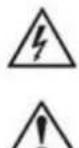
ES Lista de los principales componentes
EN List of main components
FR Nombre des composants principaux
DE Nombre der hauptkomponenten
IT Elenco dei principali componenti
PT Nombre dos componentes principais
NL Lijst van de voornamste onderdelen
RU Пелемь OCHOBHyX KOMNHOHTOB
| ES | EN | FR | DE | IT | |
| 1 | Cable | Cable | Cable | Kabel | Cavo |
| 2 | Carcasa del motor | Motor casing | Carcasse de moteur | Motorgehäuse | Carcassa del motore |
| 3 | Condensador | Capacitor | Condensateur | Kondensator | Condensatore |
| 4 | Rodete | Impeller | Roue | Laufrad | Girante |
| 5 | Cuerpo bomba | Pump casing | Corps de pompé | Pumpengehäuse | Corpo della pompa |
| 6 | Tapa aspiración | Suction cover | Fond d'aspiration | Saugdekel | Coperchio, lato aspirante |
| 7 | Pie | Foot | Pied | Fub | Piede |
| 8 | Eje motor | Motor shaft | Arbre de moteur | Motorwelle | Albero del motore |
| 9 | Rodamente | Bearing | Roulement | Wälzler | Cuscinetto |
| 10 | Cuerpo intermedio | Interstage casing | Corps intermédiaire | Zwischengehäuse | Corpo intermedió |
| 11 | Retén mecánico | Mechanical seal | Garniture mecanique | Gleitringdichtung | Tenuta meccanica |
| PT | NL | RU | AR | |
| 1 | Cabo | Kabel | Кабеловий в�� | Л�� |
| 2 | Carcasa motor | Motorhuis | Корпс злесковая差别 | Бал Бал Бал Бал Бал Бал Бал Бал Бал Бал Бал Бал Бал Бал Бал Бал Бал Бал Бал Бал Бал Бал Бал Бал Бал Бал Бал Бал Бал Бал Бал Бал Бал Бал B B B B B B B B B B B B B B B B B B B B B B B B B B B B B B B B B B B B B B B B B B B B B B B B B B C C C C C C C C C C C C C C C C C C C C C C C C C C C C C C C C C C C C C C C C C C C C C C C C C C B B B B B B B B B B B B B B B B B B B B B B B B B B B B B B B B B B B B B B B B B B B B B B B B B G G G G G G G G G G G G G G G G G G G G G G G G G G G G G G G G G G G G G G G G G G G G G G G G G G C C C C C C C C C C C C C C C C C C C C C C C C C C C C C C C C C C C C C C C C C C C C C C C C C G G G G G G G G G G G G G G G G G G G G G G G G G G G G G G G G G G G G G G G G G G G G G G G G G B B B B B B B B B B B B B B B B B B B B B B B B B B B B B B B B B B B B B B B B B B B B B B B B B R R R R R R R R R R R R R R R R R R R R R R R R R R R R R R R R R R R R R R R R R R R R R R R R R R G G G G G G G G G G G G G G G G G G G G G G G G G G G G G G G G G G G G G G G G G G G G G G G G G F F F F F F F F F F F F F F F F F F F F F F F F F F F F F F F F F F F F F F F F F F F F F F F F F F G G G G G G G G G G G G G G G G G G G G G G G G G G G G G G G G G G G G G G G G G G G G G G G G G M M M M M M M M M M M M M M M M M M M M M M M M M M M M M M M M M M M M M M M M M M M M M M M M M M G G G G G G G G G G G G G G G G G G G G G G G G G G G G G G G G G G G G G G G G G G G G G G G G G R R R R R R R R R R R R R R R R R R R R R R R R R R R R R R R R R R R R R R R R R R R R R R R R R F F F F F F F F F F F F F F F F F F F F F F F F F F F F F F F F F F F F F F F F F F F F F F F F F R R R R R R R R R R R R R R R R R R R R R R R R R R R R R R R R R R R R R R R R R R R R R R R R R L L L L L L L L L L L L L L L L L L L L L L L L L L L L L L L L L L L L L L L L L L L L L L L L L L R R R R R R R R R R R R R R R R R R R R R R R R R R R R R R R R R R R R R R R R R R R R R R R R R P P P P P P P P P P P P P P P P P P P P P P P P P P P P P P P P P P P P P P P P P P P P P P P P P P F F F F F F F F F F F F F F F F F F F F F F F F F F F F F F F F F F F F F F F F F F F F F F F F F L L L L L L L L L L L L L L L L L L L L L L L L L L L L L L L L L L L L L L L L L L L L L L L L L F F F F F F F F F F F F F F F F F F F F F F F F F F F F F F F F F F F F F F F F F F F F F F F F F P P P P P P P P P P P P P P P P P P P P P P P P P P P P P P P P P P P P P P P P P P P P P P P P P R R R R R R R R R R R R R R R R R R R R R R R R R R R R R R R R R R R R R R R R R R R R R R R R R r r r r r r r r r r r r r r r r r r r r r r r r r r r r r r r r r r r r r r r r r r r r r r r r r r l l l l l l l l l l l l l l l l l l l l l l l l l l l l l l l l l l l l l l l l l l l l l l l l l l r r r r r r r r r r r r r r r r r r r r r r r r r r r r r r r r r r r r r r r r r r r r r r r r r R 0 0 0 0 0 0 0 0 0 0 0 0 0 0 0 0 0 0 0 0 0 0 0 0 0 0 0 0 0 0 0 0 0 0 0 0 0 0 0 0 0 0 0 0 0 0 0 0 0 0 8 0 0 0 0 0 0 0 0 0 0 0 0 0 0 0 0 0 0 0 0 0 0 0 0 0 0 0 0 0 0 0 0 0 0 0 0 0 0 0 0 0 0 0 0 0 0 0 0 0 6 0 0 0 0 0 0 0 0 0 0 0 0 0 0 0 0 0 0 0 0 0 0 0 0 0 0 0 0 0 0 0 0 0 0 0 0 0 0 0 0 0 0 0 0 0 0 0 0 0 4 0 0 0 0 0 0 0 0 0 0 0 0 0 0 0 0 0 0 0 0 0 0 0 0 0 0 0 0 0 0 0 0 0 0 0 0 0 0 0 0 0 0 0 0 0 0 0 0 0 5 0 0 0 0 0 0 0 0 0 0 0 0 0 0 0 0 0 0 0 0 0 0 0 0 0 0 0 0 0 0 0 0 0 0 0 0 0 0 0 0 0 0 0 0 0 0 0 0 0 3 0 0 0 0 0 0 0 0 0 0 0 0 0 0 0 0 0 0 0 0 0 0 0 0 0 0 0 0 0 0 0 0 0 0 0 0 0 0 0 0 0 0 0 0 0 0 0 0 0 7 0 0 0 0 0 0 0 0 0 0 0 0 0 0 0 0 0 0 0 0 0 0 0 0 0 0 0 0 0 0 0 0 0 0 0 0 0 0 0 0 0 0 0 0 0 0 0 0 0 2 0 0 0 0 0 0 0 0 0 0 0 0 0 0 0 0 0 0 0 0 0 0 0 0 0 0 0 0 0 0 0 0 0 0 0 0 0 0 0 0 0 0 0 0 0 0 0 0 0 1 0 0 0 0 0 0 0 0 0 0 0 0 0 0 0 0 0 0 0 0 0 0 0 0 0 0 0 0 0 0 0 0 0 0 0 0 0 0 0 0 0 0 0 0 0 0 0 0 0 9 0 0 0 0 0 0 0 0 0 0 0 0 0 0 0 0 0 0 0 0 0 0 0 0 0 0 0 0 0 0 0 0 0 0 0 0 0 0 0 0 0 0 0 0 0 0 0 0 0 、 F 1 1 1 1 1 1 1 1 1 1 1 1 1 1 1 1 1 1 1 1 1 1 1 1 1 1 1 1 1 1 1 1 1 1 1 1 1 1 1 1 1 1 1 1 1 1 1 1 1 1 2 0 0 0 0 0 0 0 0 0 0 0 0 0 0 0 0 0 0 0 0 0 0 0 0 0 0 0 0 0 0 0 0 0 0 0 0 0 0 0 0 0 0 0 0 0 0 0 0 8 1 1 1 1 1 1 1 1 1 1 1 1 1 1 1 1 1 1 1 1 1 1 1 1 1 1 1 1 1 1 1 1 1 1 1 1 1 1 1 1 1 1 1 1 1 1 1 1 1 8 1 1 1 1 1 1 1 1 1 1 1 1 1 1 1 1 1 1 1 1 1 1 1 1 1 1 1 1 1 1 1 1 1 1 1 1 1 1 1 1 1 1 1 1 1 1 1 1 8 2 1 1 1 1 1 1 1 1 1 1 1 1 1 1 1 1 1 1 1 1 1 1 1 1 1 1 1 1 1 1 1 1 1 1 1 1 1 1 1 1 1 1 1 1 1 1 1 1 1 6 1 1 1 1 1 1 1 1 1 1 1 1 1 1 1 1 1 1 1 1 1 1 1 1 1 1 1 1 1 1 1 1 1 1 1 1 1 1 1 1 1 1 1 1 1 1 1 1 1 4 1 1 1 1 1 1 1 1 1 1 1 1 1 1 1 1 1 1 1 1 1 1 1 1 1 1 1 1 1 1 1 1 1 1 1 1 1 1 1 1 1 1 1 1 1 1 1 1 1 5 1 1 1 1 1 1 1 1 1 1 1 1 1 1 1 1 1 1 1 1 1 1 1 1 1 1 1 1 1 1 1 1 1 1 1 1 1 1 1 1 1 1 1 1 1 1 1 1 1 3.5 1.5 1.5 1.5 1.5 1.5 1.5 1.5 1.5 1.5 1.5 1.5 1.5 1.5 1.5 1.5 1.5 1.5 1.5 1.5 1.5 1.5 1.5 1.5 1.5 1.5 5.5 5.5 5.5 5.5 5.5 5.5 5.5 5.5 5.5 5.5 5.5 5.5 5.5 5.5 5.5 5.5 5.5 5.5 5.5 5.5 5.5 5.5 5.5 5.5 5.5 8.5 8.5 8.5 8.5 8.5 8.5 8.5 8.5 8.5 8.5 8.5 8.5 8.5 8.5 8.5 8.5 8.5 8.5 8.5 8.5 8.5 8.5 8.5 8.5 8.5 5.5 5.5 5.5 5.5 5.5 5.5 5.5 5.5 5.5 5.5 5.5 5.5 5.5 5.5 5.5 5.5 5.5 5.5 5.5 5.5 5.5 5.5 5.5 5.5 6.5 6.5 6.5 6.5 6.5 6.5 6.5 6.5 6.5 6.5 6.5 6.5 6.5 6.5 6.5 6.5 6.5 6.5 6.5 6.5 6.5 6.5 6.5 6.5 6.5 8.5 8.5 8.5 8.5 8.5 8.5 8.5 8.5 8.5 8.5 8.5 8.5 8.5 8.5 8.5 8.5 8.5 8.5 8.5 8.5 8.5 8.5 8.5 8.5 6.5 6.5 6.5 6.5 6.5 6.5 6.5 6.5 6.5 6.5 6.5 6.5 6.5 6.5 6.5 6.5 6.5 6.5 6.5 6.5 6.5 6.5 6.5 6.5 5.5 5.5 5.5 5.5 5.5 5.5 5.5 5.5 5.5 5.5 5.5 5.5 5.5 5.5 5.5 5.5 5.5 5.5 5.5 5.5 5.5 5.5 5.5 5.5 4.5 4.5 4.5 4.5 4.5 4.5 4.5 4.5 4.5 4.5 4.5 4.5 4.5 4.5 4.5 4.5 4.5 4.5 4.5 4.5 4.5 4.5 4.5 4.5 4.5 6.5 6.5 6.5 6.5 6.5 6.5 6.5 6.5 6.5 6.5 6.5 6.5 6.5 6.5 6.5 6.5 6.5 6.5 6.5 6.5 6.5 6.5 6.5 6.5 4.5 4.5 4.5 4.5 4.5 4.5 4.5 4.5 4.5 4.5 4.5 4.5 4.5 4.5 4.5 4.5 4.5 4.5 4.5 4.5 4.5 4.5 4.5 4.5 8.5 8.5 8.5 8.5 8.5 8.5 8.5 8.5 8.5 8.5 8.5 8.5 8.5 8.5 8.5 8.5 8.5 8.5 |
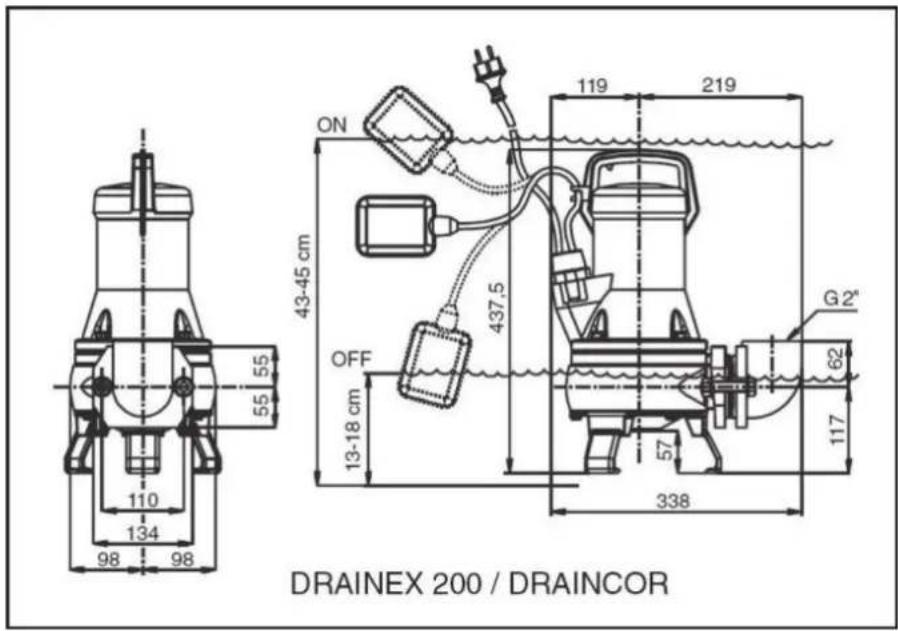
Fig.1 / Abb.1 / Afb.1 / Pnc.1
| 230 V 50 Hz | 230/400 V | Q max. [l/min] | H max. [m] | A 1~230V | A 3~400V | C μF | P1 [kW] | IP | η(%) | ∅ | T [kg] | |
| DRAINEX 200 | √ | √ | 400 | 12 | 5,2 | 2,3 | 16 | 1,1 | 68 | 35 | 2" | 29 |
| DRAINEX 201 | √ | √ | 450 | 14 | 6,2 | 2,6 | 16 | 1,4 | 68 | 36 | 2" | 29 |
| DRAINEX 202 | √ | √ | 516 | 16 | 7,4 | 2,8 | 16 | 1,6 | 68 | 37 | 2" | 29 |
| DRAINEX 300 | √ | √ | 570 | 8 | 5,5 | 2,4 | 16 | 1,2 | 68 | 25 | 2 1/2" | 33,5 |
| DRAINEX 301 | √ | √ | 640 | 10 | 6,8 | 2,7 | 16 | 1,5 | 68 | 28 | 2 1/2" | 33,5 |
| DRAINEX 302 | √ | √ | 700 | 12 | 7,8 | 3 | 16 | 1,8 | 68 | 32 | 2 1/2" | 33,5 |
| DRAINCOR 180 | √ | √ | 190 | 21 | 7,6 | 2,7 | 16 | 1,6 | 68 | 25 | 1 1/2" | 30 |
| DRAINXOR 200 | - | √ | 290 | 22 | - | 3 | - | 1,8 | 68 | 30 | 1 1/2" | 30 |