Tecnoplus 25 - Pump ESPA - Free user manual and instructions
Find the device manual for free Tecnoplus 25 ESPA in PDF.

| Product type | Horizontal multistage pump with electronic regulator |
| Brand | ESPA |
| Model | Tecnoplus 25 |
| Power supply | Single-phase, voltage and frequency per nameplate |
| Maximum pressure | 4.5 bar |
| Adjustable set pressure | 1.5 to 4.5 bar (recommended 3.5 bar max) |
| Minimum flow rate | 2 l/min |
| Check valve | Integrated |
| Motor thermal protection | Integrated |
| LED indicators | LINE (voltage), RUN (running), FAULT (fault) |
| Pressure adjustment | By + and - buttons (pump running) |
| Dry running protection | Yes, with automatic restart attempts |
| Liquid temperature | 4 °C to 40 °C |
| Ambient temperature | 0 °C to 40 °C |
| Storage temperature | -10 °C to 50 °C |
| Priming | Manual by filling water through the plug |
| Maintenance | No regular maintenance required; drain during freezing periods |
| Installation | Fixation on solid base, suction pipe ≥ orifice diameter, max height 5 m above water |
| Compliance | EC Directives: Machinery, EMC, Low Voltage, WEEE, etc. |
| External level probe | Optional (model IN15 ESPA) |
| Repairability | Intervention by authorized technician only |
| Spare parts | Available from ESPA technical service |
Frequently Asked Questions - Tecnoplus 25 ESPA
User questions about Tecnoplus 25 ESPA
0 question about this device. Answer the ones you know or ask your own.
Ask a new question about this device
Download the instructions for your Pump in PDF format for free! Find your manual Tecnoplus 25 - ESPA and take your electronic device back in hand. On this page are published all the documents necessary for the use of your device. Tecnoplus 25 by ESPA.
USER MANUAL Tecnoplus 25 ESPA
natural_image
Technical line drawing of a mechanical pump or motor assembly (no text or symbols)EN Instruction manual.... 11 (Translation from the original Spanish)
EN: EVIDENCE OF CONFORMITY
We declare, under our responsibility, that the products in this manual comply with the following directives and standards:
- Directive 2006/42/EC (Machine Security): Standard EN 809 and EN 60204-1
- Directive EMC 2014/30/EU (Electromagnetic compatibility): Standard EN 61000-6-1 and EN 61000-6-3
- Directive 2014/35/EU (Low voltage): Standard EN 60335-1 and EN 60335-2-41
- Directive 2009/125/EC (ecological design): Regulation (EU) 2019/1781 electrical motors and variable speed drives. Standard EN 60034-30.
- Directive 2012/19/EU (on waste electrical and electronic equipment (WEEE)): Standard EN 50419:2006 about marking of electrical and electronic equipment.
- Directive 2011/65/UE (Restriction of hazardous sustances): Standard EN 50581.
EVIDENCE OF CONFORMITY
We declare, under our responsibility, that the products in this manual comply with the following directives and standards:
- Supply of Machinery (Safety) Regulations 2008: Standard BS 809 and BS 60204-1
- Electromagnetic Compatibility Regulations 2016: Standard BS 61000-6-1 and BS 61000-6-3.
- Electrical Equipment (Safety) Regulations 2016: Standard BS 60335-1 and BS 60335-2-41.
- The Ecodesign for Energy-Related Products and Energy Information (Amendment) (EU Exit) Regulations 2019: Standard BS 60034-30.
- The Restriction of the Use of Certain Hazardous Substances in Electrical and Electronic Equipment Regulations 2012. Standard BS 50581.
Banyoles, July 15th 2022
Josep Unyó (Technical Manager)
ESPA 2025, SL
Ctra. de Mieres, s/n - 17820 Banyoles
Girona - Spain
text_image
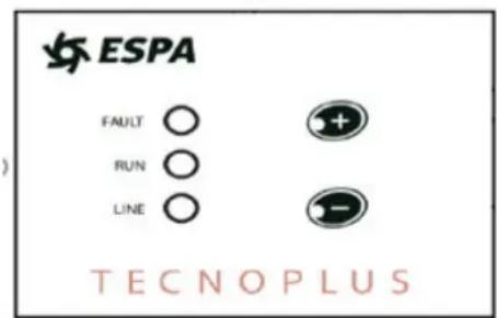
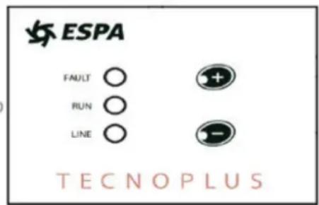
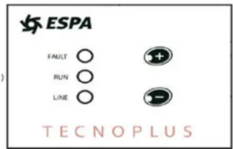
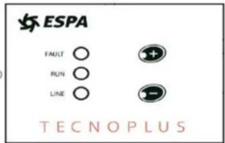
FAULT RUN LINE - + ESPAPanel de control TECNOPLUS 25
text_image
ESPA FAULT ○ RUN ○ LINE ○ TECNOPLUSFault: Led de error.
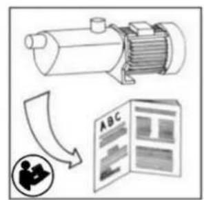
Damage prevention and safety instructions (See figure 4)
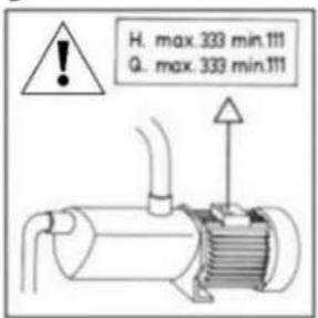
| A | Warning! Observe limitations of use. |
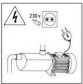
| B | The nameplate voltage must be the same as the mains voltage. |
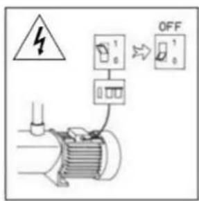
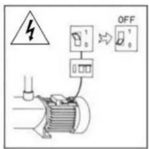
| C | Connect the pump to the mains via an omnipolar switch with at least a 3 mm opening between contacts. |
| D | Install a high-sensitivity differential switch (0.03A) as extra protection against lethal electric shocks. |
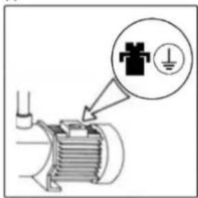
| E | Connect the pump to the ground. |
| F | Use pump only within performance limits indicated on the nameplate. |
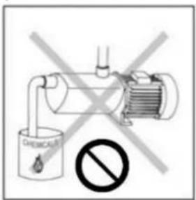
| G | Be careful with hazardous liquids and environments. |
| H | Do not carry the pump by the power cable. |
| I | This apparatus may be used by children 8 years or older and persons with reduced physical, sensory or mental capacities, or lacking experience and knowledge, if they are supervised or receive adequate training on the safe use of the apparatus and understand the dangers.Children should not be allowed to play with the apparatus.Children should not perform the ordinary cleaning and maintenance tasks without supervision. |
| J | Attention to hazardous liquids and environments. |
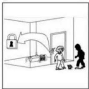
| K | Attention to accidental losses.Do not expose the electric pump to the outdoors. |
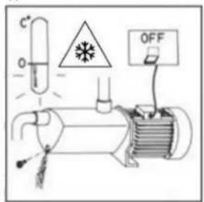
| L | Caution! Avoid icing.Disconnect from the mains before carrying out any maintenance work. |
Contents
Safety precautions 11
-
General information.... 12
-
Handling....12
-
Installation 12
3.1. Fixing 12
3.2. Suction pipe assembly 12
3.3. Discharge pipe assembly 12
3.4. Electrical connection 13
3.5. Checks prior to initial start-up..... 13
- Starting 13
4.1. Start-up and operation.... 13
4.2. Set point pressure adjustment..... 13
4.3. Fault detection / Automatic restarting .. 14
-
Nameplate 14
-
Level Probe (Tecnoplus 25) ..... 14
-
Maintenance 14
-
Product disposal 15
-
Technical data 15
-
Led Indicators (Tecnoplus 25) ...... 15
-
List of possible failures, causes and solutions .... 16
-
Illustrations.... 65
Safety precautions
This symbol together with one of the following words “Danger” or “Warning” indicates the risk level deriving from failure to observe the prescribed safety precautions:

DANGER risk of electric shock
Warns that failure to observe the precautions involves a risk of electric shock.

DANGER
Warns that failure to observe the pre cautions involves a risk of damage to persons and/or things.

WARNING
Warns that failure to observe the pre cautions involves the risk of damaging the pump and/or the facility.
1. GENERAL INFORMATION
Please observe the following instructions to achieve the best pump performance possible and a trouble free installation.

Read these instructions before installing the pump.
Save them for future reference.
They are horizontal multicell centrifugal pumps, composed of several turbines in series that obtain the same flow rate at different pressures, depending on the number of turbines arranged.
They are designed to work with clean water, free of solids in suspension and at a maximum temperature of 40^ C.
The TECNOPLUS pump with regulator is composed of a check valve, LED's for indication and control electronics..
It has been developed to automate starting and stopping and varies the motor speed to maintain a constant pressure. The electronic control also protects against running without water.
As long as any faucet is kept open, the pump will keep running.
When the taps are closed, the pump stops running.
Proper adherence to the installation and operating instructions and electrical wiring diagrams will ensure proper operation of the pump.
Failure to follow the instructions in this manual may result in motor overloads, reduced technical characteristics, shortened pump life and consequences of all kinds, for which we decline any responsibility.
2. HANDLING
The pumps are supplied suitably packaged to prevent damage in transit. Before unpacking, check that the packaging has not been damaged or de-formed,

Lift and handle the product with care and with the right tools.
3. INSTALLATION
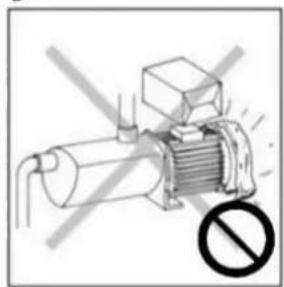
These pumps are designed for indoor use.
Make sure that pump is never submerged and that it rests in a dry and well aired room.
3.1. Fixing
The pump should be fixed to a solid base by means of screws, taking advantage of the holes in the support in order to avoid undesirable noise and vibrations.
The pump should be protected from flooding and provided with dry ventilation.
If you wish to fix the pump, use 2 ∅8 screws and take advantage of the holes in the bracket.
3.2. Suction pipe assembly
The piping must have the same diameter or, if the distance is more than 7 meters higher from the pump inlet, a minimum upward slope of 2% must be permanently guaranteed in order to avoid air pockets.
If the pump is installed at suction, it should be installed as close as possible to the water level in order to reduce the suction stroke to avoid head losses. It is not recommended to install the pump more than 5 m. geometric height from the water level. The installation of a check valve at the suction base is recommended.
The suction pipe must be submerged at least 30 cm below the dynamic water level.
3.3. Discharge pipe assembly

It is forbidden to install a check valve in the rising main.
Assemble the Kitpres and pressure gauge according to Fig. 5.
It is recommended to use pipes of the same diameter as the delivery port or larger to reduce head losses
in long and winding pipe runs.
Piping should never rest its weight on the pump.
Sealing adhesive should not be used to seal pump connections. Use sealing tape for this purpose.
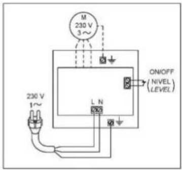
3.4. Electrical connection.
CONNECTING THE PUMP TO THE MAINS (Fig.1)

The electrical installation shall have a multiple separation system with contact opening ≥ 3mm.
The protection of the system shall be based on a differential switch ( I=30 mA ).
The electrical connection shall be made by connecting the pump socket directly to a domestic power socket duly protected according to the regulations in force in each country. The electrical connections must be made according to IEC-60364 (electrical installations in buildings) or according to the regulations in force in the country of destination.

Single-phase motors have built-in thermal protection.
3.5. Checks prior to initial start-up

Check that the mains voltage and frequency correspond to those indicated on the nameplate.
Make sure that the pump shaft rotates freely.
Fill the pump body completely with water through the filler plug. If you have installed a foot valve, fill the suction pipe.
Make sure that there are no leaking seals or fittings.
THE PUMP MUST NEVER RUN WITHOUT WATER.

The electrical installation must be effectively grounded and must comply with current national regulations.
4. STARTING
4.1. Start-up and operation
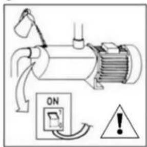
Open all shut-off valves in the system, both suction and discharge.
Switch on the power supply. The LINE voltage indicator lights up.
The pump-motor unit starts automatically. During operation of the pump, the (RUN) indicator lights up. During this operation, keep a water outlet tap open to purge the air from the installation. Once the installation has been purged, close the tap and the unit will stop after ± 10 seconds. Only the voltage indicator (LINE) will be illuminated.
If the pump is not properly primed or there is no water to feed it, the pump will stop after 10 seconds and the LED (FAULT) will light up. To complete the priming of the pump, press the (+) and (-) keys simultaneously, thus restarting the circuit and the 10-second timer.
With a water consumption of more than 2 l/min the pump is always running, below this consumption the control flashes the RUN LED to indicate that we are below the minimum flow rate and after about 10 seconds the pump stops.
If the motor does not work or does not extract water, try to find out the anomaly through the list of the most common possible faults and their possible solutions that we provide on the following pages.
4.2. Set point pressure adjustment.
To raise or lower the setpoint pressure, the pump must be running and the RUN LED must be permanently lit. By pressing and holding one of the two control buttons (+) or (-) the set pressure is varied.
The start pressure is set to 0.5 bar below the set pressure.
Control panel TECNOPLUS 15
text_image
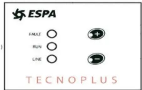
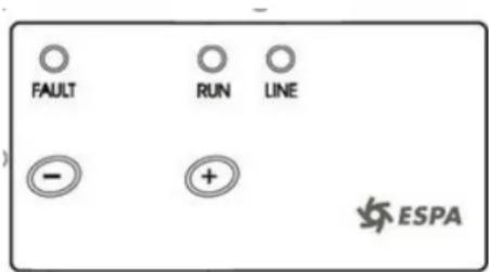
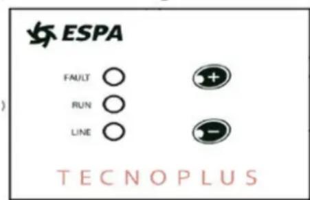
FAULT RUN LINE - + ESPAControl panel TECNOPLUS 25
text_image
ESPA FAULT ○ RUN ○ LINE ○ TECNOPLUSFault: Error LED.
Run: Always on when the engine is running. If it flashes, it indicates low or minimum flow.
Line: Mains voltage indicator.
+ - : Set pressure adjustments.
Considerations:
The set pressure must be 10 m. (1 bar.) above the highest tap of the installation (H.max).
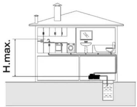
text_image
H.max.| Set point pressures (bar) | |||
| Minimum | Maximum recommended | Limit | |
| Tecnoplus 15 | 1,5 | 2,5 | 3,5 |
| Tecnoplus 25 | 1,5 | 3,5 | 4,5 |
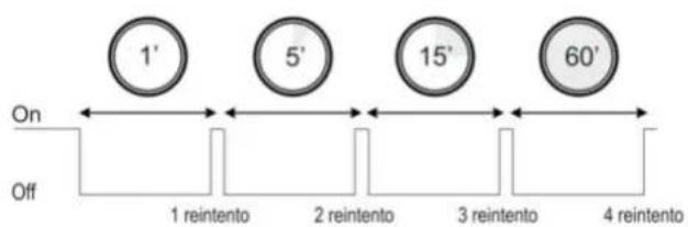
4.3. Fault detection / Automatic restarting
In the event that the electronic circuit detects a lack of water, it will stop the pump and the alarm LED will flash. The circuit will make 4 attempts to connect and if no attempt is successful in re-establishing the pressure due to lack of water, the circuit will remain in fault mode indefinitely until it is manually reactivated.
While the pump is stopped in fault mode, waiting for a retry the alarm LED will be flashing and if 4 unsuccessful retries have been made, the alarm LED will always remain active.
The following graph illustrates the time that elapses between the different retries in the event of not succeeding in any of them.
text_image
1' 5' 15' 60' On Off 1 reintento 2 reintento 3 reintento 4 reintentoPressing the (+) and (-) buttons simultaneously resets the circuit.
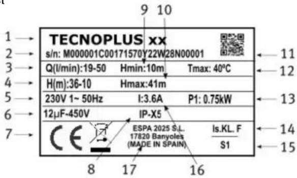
5. NAMEPLATE
text_image
TECNOPLUS xx s/n: M000001C00171570Y22W28N00001 Q(l/min):19-50 Hmin:10m Tmax: 40°C H(m):36-10 Hmax:41m 230V 1~ 50Hz I:3.6A P1: 0.75kW 12μF-450V IP-X5 CE ESPA 2025 S.L. 17820 Banyoles (MADE IN SPAIN) Is.KL. F S1 8 17 16 11 12 13 14 15DESCRIPCIÓN
| 1 | Article reference |
| 2 | Pump serial number |
| 3 | Flow |
| 4 | Pressure |
| 5 | Rated voltaje, number of fases, AC current symbol and frequency |
| 6 | Condensator |
| 7 | EC mark + year of manufacture |
| 8 | Degree protección against moisture |
| 9 | Minimum working pressure |
| 10 | Maximum pressure |
| 11 | QR code with information serial number |
| 12 | T máx. of liquid |
| 13 | Absorbed motor power (P1) |
| 14 | Motor insulation designation |
| 15 | Symbol continuous operation |
| 16 | Maximum rated current at rated voltage |
| 17 | Name and address of the seller responsible for the product |
6. LEVEL PROBE (Tecnoplus 25)
It is possible to install an external level probe for the suction tank. The probe must be of the float type (model IN15 ESPA). See connection diagram fig. 1.
Never open the cover without having disconnected the power supply for at least 5 minutes.
7. MAINTENANCE
Our pumps are maintenance-free.
In times of frost, be careful to empty the pipes. If the pump is not to be used for a long period of time, it is recommended to dismantle it and store it in a dry and ventilated place.
WARNING: in the event of a fault, the pump must only be handled by an authorized service technician.
The list of Official Technical Services can be found at www.espa.com.
8. PRODUCT DISPOSAL
When it is time to dispose of the pump, it does not contain any toxic or polluting material. The main components are properly identified for selective disposal.
Disposal of this product or parts of it must be carried out in an environmentally friendly manner. Use your local waste collection service. If this is not possible, please contact your nearest ESPA service.
9. TECHNICAL DATA
Liquid temperature:....4.°C - 40°C
Ambient temperature:.... 0°C - 40°C
Storage temperature: -10^ - 50°C
10. LED INDICATORS (TECNOPLUS 25 Model)
When the equipment is switched on, a sequence is initiated:
- The LEDs light up twice consecutively.
- The unit starts up.
The possibilities of the LED'S are
0=Led OFF
1=Led ON
2=Slow flashing LED (2s. On/2s. Off)
3=Fast flashing LED (1s. On/1s. Off)
4=Led flashing very fast (0.2s. On/0.2s. Off)
| Led's position when the pump is running | |||
| LINE | RUN | FAULT | Equipment Status |
| 1 | 1 | 0 | Normal operation. Pump is running. |
| 1 | 3 | 0 | Flow rate too low. If it remains in this state for more than 10 sec. the pump will stop. |
| Led's position when the pump is stopped | |||
| LINE | RUN | FAULT | Equipment status |
| 1 | 0 | 0 | Normal operation. The pump is waiting for a flow request. |
| 1 | 2 | 0 | Lack of tank level. When the water level recovers, the pump starts automatically. |
| 1 | 0 | 3 | Dry running error. The pump has stopped due to lack of water and the equipment is cycling through the automatic restart attempts. . |
| 1 | 0 | 1 | Dry running alarm. The equipment is stopped due to lack of water until the manual reset is carried out. |
| 1 | 3 | 3 | Lack of pressure alarm. If the unit detects water circulation and the pressure is below 0.3 bar. The pump stops. It must be reset manually.1 0 4 Pressure transducer alarm. If communication is restored, the unit starts up automatically. |
| 1 | 0 | 4 | Pressure transducer alarm. If communication is restored, the unit starts up automatically. |
| 1 | 2 | 2 | Current error. The pump has stopped due to an overcurrent and the equipment is cycling through the automatic reset attempts (4). |
| 1 | 2 | 1 | Current alarm. The equipment is stopped due to overcurrent until the manual reset is carried out. |
| 1 | 4 | 4 | Short circuit error. The pump has stopped due to an overload and the unit is making the cycle of attempts for automatic reset (4). |
| 1 | 4 | 1 | Short circuit alarm. The equipment is stopped due to overloads until the manual reset is carried out. |
| 2 | 0 | 2 | Voltage error. When the power supply voltage recovers within the established margins, the pump will start up automatically. |
| 1 | 0 | 2 | Internal alarm. Electronic communication failure. Disconnect the pump from the power supply and reconnect by pressing (+) and (-) simultaneously. Depending on the fault, the equipment will restart or remain in fault mode. |
11. LIST OF POSSIBLE FAILURES, CAUSES AND SOLUTIONS
- The engine does not start.
- Engine runs but does not give pressure.
- Excessive engine overheating.
- The flow rate is insufficient.
- Motor stops and starts automatically (Klixon).
- Shaft rotates with difficulty.
| 1 | 2 | 3 | 4 | 5 | 6 | POSSIBLE PROBLEM | SOLUTIONS |
| X | X | X | Pump blocked | Disconnect it and take it to the official Technical Service | |||
| X | Foot valve clogged | Clean it or replaced by new one | |||||
| X | X | Total head higher than expected | Verify geometric head and loss of head | ||||
| X | X | X | Wrong tension | Check that the tension is the same as that on the name plate | |||
| X | X | Water level in well or tank has come down | Verify suction head | ||||
| X | Fuse or thermal relay disconnected | Change fuse or thermal relay | |||||
| X | X | Impellers are worn out | Disconnect pump and take it to your Service Dealer | ||||
| X | Foot valve not submerged | Be sure suction pipe is submerged | |||||
| X | Pump was not primed | Fill pump body with water | |||||
| X | X | Room not properly aired | Provide good ventilation | ||||
| X | Air entry | Seal unions and joints properly |
text_image
FAULT RUN LINE - + ESPA2=La LED clignote lentement (2s. On/2s. Off)
3=La LED clignote rapidement (1s. On/1s. Off)
text_image
FAULT RUN LINE - + ESPABedienfeld TECNOPLUS 25
text_image
ESPA FAULT ○ RUN ○ LINE ○ TECNOPLUSFault: Fehler-LED.
text_image
FAULT RUN LINE - + ESPA2 = LED lampeggiante lento (2s. On/2s. Off)
3=LED lampeggiante veloce (1s. On/1s. Off)
text_image
FAULT RUN LINE - + ESPAPanel de control TECNOPLUS 25
text_image
ESPA FAULT ○ RUN ○ LINE ○ TECNOPLUSFault: Led de error.
text_image
FAULT RUN LINE - + ESPAControlepaneel TECNOPLUS 25
text_image
ESPA FAULT ○ RUN ○ LINE ○ TECNOPLUSFault: Fout LED.
text_image
FAULT RUN LINE - + ESPAtext_image
FAULT RUN LINE - + ESPATECNOPLUS 25 控制面板
text_image
ESPA FAULT ○ RUN ○ LINE ○ TECNOPLUSFault: 故障: 故障LED。
63.....(Tecnoplus 25) LED .10
يجب الاضخةuchiuchiuchiuchiuchiuchiuchiuchiuchiuchiuchiuchiuchiuchiuchiuchiuchiuchiuchiuchiuchiuchiuchiuchiuchiuchiuchiuchiuchiuchiuchiuchiuchiuchiuchiuchiuchiuchiuchiuchiuchiuchiuchiuchiuchiuchiuchiuchiuchiuchiuchiuchiuchiuchiuchiuchiuchiuchiuchiuchiuchiuchiuchiuchiuchiuchiuchiuchiuchiuchiuchiuchiuchiuchiuchiuchiuchiuchiuchiuchiuchiuchiuchiuchiuchiuchiuchiuchiuchiuchiuchiuchiuchiuchiuchiuchiuchiuchiuchiuchiushi.
4.1. trades Shanghai and the
text_image
FAULT RUN LINE - + ESPA(1s. Off/1s. On) وrylic سريع Led=3
text_image
① ② ③ M ~ ⑤ ④ ③ MOTOR L N L N L NTecnoplus15
text_image
M 230 V 3~ ON/OFF (NIVEL) (LEVEL) 230 V 1~ L N 200Tecnoplus25
| 1 | ROJO | 2 | BLANCO | 3 | NEGRO | 4 | MARRÓN | 5 | VERDE-AMARILLO |
| RED | WHITE | BLACK | BROWN | GREEN-YELLOW | |||||
| ROUGE | BLANC | NOIR | MARRON | VERT-JAUNE | |||||
| ROT | WEISS | SCHWARZ | BRAUN | GRÜN-GELB | |||||
| ROSSO | BIANCO | NERO | MARRONE | VERDE-GIALLO | |||||
| VERMELHO | BRANCO | PRETO | CASTAÑO | VERDE-AMARELO | |||||
| RODE | WITTE | ZWARTE | BRUIN | GEEL-GROEN | |||||
| KPACHЫЙ | БЕЛЫЙ | ЧЕРНИТЬ | КОРИЧНЕВЫЙ | ЖЕЛТО-ЗЕЛЕНЫЙ | |||||
| 红色的 | 白色的 | 黑色的 | 棕色的 | 黄绿色 | |||||
| أحمر | أبيض | اسود | بنى | أصفر أخضر |
Fig. 2 / Abb. 2 / Afb. 2
text_image
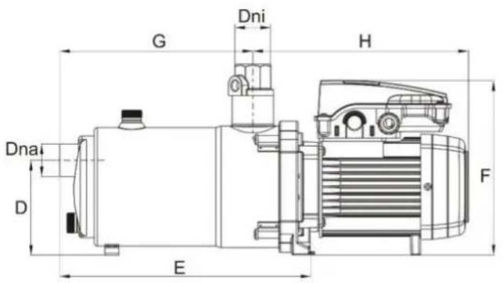
G Dni H Dna D E F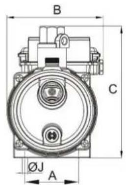
text_image
B C ØJ A| TECNOPLUS230V 50Hz | Q max[l/min] | H max[m] | A 1~ | C | P1[kW] | IP | η(%) | dBa±1 | A[mm] | B[mm] | C[mm] | D[mm] | E[mm] | F[mm] | G[mm] | H[mm] | ∅J | Dna | Dni | PA | Tl[kg] |
| 230V | μF | ||||||||||||||||||||
| TECNOPLUS 15 | 65 | 44 | 3,6 | 12 | 0.8 | X5 | 35 | <70 | 88 | 158 | 216 | 107 | 285 | 197 | 219 | 244 | 9 | Rp 1" | Rp 1" | 1,7 | 9 |
| TECNOPLUS 25 | 108 | 50 | 8,5 | -- | 1,3 | X5 | 35 | <70 | 88 | 149 | 216 | 107 | 468 | 221 | 190 | 278 | 9 | Rp 1" | Rp 1" | 1,7 | 10,5 |
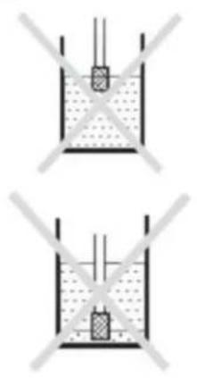
Fig.3 / Abb.3 / Afb.3
natural_image
Two identical diagrams showing a container with liquid and two cross-sectional lines, no text or symbols present.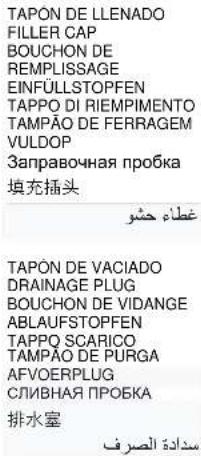
text_image
TAPON DE LLENADO FILLER CAP BOUCHON DE REMLISSAGE EINFÜLLSTOPFEN TAPPO DI RIEMPIMENTO TAMPÃO DE FERRAGEM VULDOP Заправочная пробка 填充插头 غطاء حشو TAPON DE VACIADO DRAINAGE PLUG BOUCHON DE VIDANGE ABLAUFSTOPFEN TAPPO SCARICO TAMPÃO DE PURGA AFVOERPLUG СЛИВНАЯ ПРОБКА 排水室 سGuidة colors
text_image
Máx. 5 m.Fig.4/Abb.4/A.4
text_image
Diagram illustrating a mechanical system with an electric motor and its corresponding document labeled ABC, accompanied by a circular icon showing a person.A
text_image
230 V ###B
text_image
Diagram showing electrical hazard symbol, switch, and OFF button with labeled componentsC
text_image
Electrical warning symbol and diagram showing a fuse, switch, and OFF button with Chinese labelsD
text_image
Diagram showing a motor with a magnified view of the gear and electrical symbol, likely indicating a mechanical or electrical component.E
text_image
H. max. 333 min.111 Q. max. 333 min.111F
text_image
Diagram illustrating a mechanical or electrical system with ON/OFF switch and warning symbolG
natural_image
Diagram of an electric motor with a prohibition symbol (no text or labels present)H
natural_image
Simple line drawing of a room with a lock, a door, and a person walking (no text or symbols)I
text_image
CHEMICAL NO]
text_image
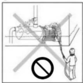
Safety warning illustration showing a person disinfecting an industrial pipe with a 'No' symbol belowK
text_image
Diagram of an electrical circuit with labeled components including a thermometer, warning symbol, and OFF buttonL
Fig.5/Abb.5/A.5
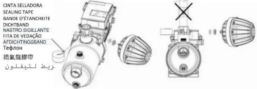
Montaje accesorios Assembly accessories Montage accessoire Versammlung zusatzgerät Montaggio accessori Montagem acessórios Assemblage accessoires Сборка принадлежностей تركيلملحقات 安装配
text_image
CINTA SELLADORA SEALING TAPE BANDE D'ÉTANCHEITE DICHTBAND NASTRO SIGILLANTE FITA DE VEDAÇÃO AFDICHTINGSBAND Telefon 鐵氣龍膠帶10-10-10-10-10-10-10-10-10-10-10-10-10-10-10-10-10-10-10-10-10-10-10-10-10-10-10-10-10-10-10-10-10-10-
text_image
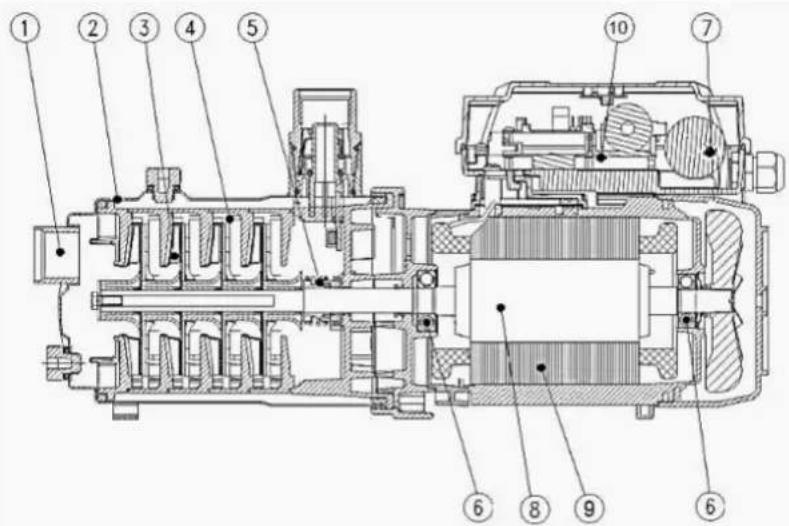
Technical cross-sectional diagram of a mechanical device with numbered components for identification.TECNOPLUS 25
text_image
Technical cross-sectional diagram of a mechanical assembly with numbered components for identification.| ES | EN | FR | DE | IT | PT | |
| 1 | Cuerpo aspiración | Suction casing | Corps d'aspiration | Sauggehäuse | Corpo aspirante | Corpo de aspiração |
| 2 | Cuerpo bomba | Pump casing | Corps de pompe | Pumpengehäuse | Corpo della pompa | Corpo de bomba |
| 3 | Rodete | Impeller | Roue | Laufrad | Girante | Impulsor |
| 4 | Difusor | Diffuser | Diffuseur | Leitrad | Difusor | Difusor |
| 5 | Cierre mecânico | Mechanical seal | Garniture mécanique | Gleintringdichtung | Tenuta meccanica | Fecho mecânico |
| 6 | Rodamiento | Bearing | Roulement | radialkugellager | Cusinetto | Rolamento |
| 7 | Condensador | Capacitor | Condensateur | Kondensator | Condensatore | Condensador |
| 8 | Eje del motor | Motor shaft | Arbre de moteur | Motorwelle | Albero del motore | Veio de motor |
| 9 | Estator | Stator | Stator | Stator | Estator | Stator |
| 10 | Circuito eléctrico | Electrical circuit | Circuit électrique | Stromkreis | Circuito elettrico | Circuito eléctrico |