
222843 - Food Processor Hendi - Free user manual and instructions
Find the device manual for free 222843 Hendi in PDF.
| Product type | Professional food processor |
| Brand | Hendi |
| Model | 222843 |
| Dimensions (L x W x H) | 560 x 500 x 880 mm |
| Net weight | 78 kg |
| Power supply | 220-240 V ~ 50/60 Hz |
| Rated power | 1100 W |
| Bowl capacity | 20 L |
| Maximum flour quantity | 5.0 kg |
| Available speeds | 3 speeds (hook: 197 rpm, flat beater: 317 rpm, whisk: 462 rpm) |
| Included accessories | Dough hook, flat beater, whisk |
| Protection class | Class I (earthing mandatory) |
| Ingress protection | IP21 |
| Maximum noise level | < 70 dB(A) |
| Intended use | Professional use: mixing, kneading, emulsifying/whipping |
| Bowl material | Stainless steel (estimated) |
| Maintenance | Manual cleaning; do not immerse, do not wash in dishwasher |
| Safety | 3 safety devices: bowl, lid, lifting lever |
| Spare parts | Detailed list of parts in the manual (over 40 references) |
| Warranty | 12 months from date of purchase |
Frequently Asked Questions - 222843 Hendi
User questions about 222843 Hendi
0 question about this device. Answer the ones you know or ask your own.
Ask a new question about this device
Download the instructions for your Food Processor in PDF format for free! Find your manual 222843 - Hendi and take your electronic device back in hand. On this page are published all the documents necessary for the use of your device. 222843 by Hendi.
USER MANUAL 222843 Hendi
natural_image
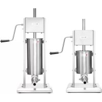
Exterior view of a modern kitchen mixer with control panel and side legs (no visible text or symbols)You should read this user manual carefully before using the appliance.
GB: Read user manual and keep this with the appliance.
natural_image
Simple icon of a house with an arrow pointing left, labeled 'INDOOR' below (no other text or symbols)GB: For indoor use only.


Thank you for purchasing this HENDI appliance. Before using the appliance for the first time, please read this manual carefully, paying particular attention to the safety regulations outlined below.
Safety regulations
- This appliance is not intended for household use.
- The appliance must only be used for the purpose for which it was intended and designed. The manufacturer is not liable for any damage caused by incorrect operation and improper use.
- Keep the appliance and electrical plug away from water and any other liquids. In the event that the appliance should fall into water, immediately remove plug from the socket and do not use until the appliance has been checked by a certified technician. Failure to follow these instructions could cause a risk to lives.
- Never attempt to open the casing of the appliance yourself.
- Do not insert any objects in the casing of the appliance.
- Do not touch the plug with wet or damp hands.
- DANGER OF ELECTRIC SHOCK! Do not attempt to repair the appliance yourself. In case of malfunctions, repairs are to be conducted by qualified personnel only.
- Never use a damaged appliance! Disconnect the appliance from the electrical outlet and contact the retailer if it is damaged.
- c! Do not immerse the electrical parts of the appliance in water or other liquids. Never hold the appliance under running water.
- Regularly check the power plug and cord for any damage. If the power plug or power cord is damaged, it must be replaced by a service agent or similarly qualified persons in order to avoid danger or injury.
- Make sure the cord does not come in contact with sharp or hot objects and keep it away from open fire. To pull the plug out of the socket, always pull on the plug and not on the cord.
- Ensure that the cord (or extension cord) is positioned so that it will not cause a trip hazard.
• Always keep an eye on the appliance when in use. - WARNING As long as the plug is in the socket the appliance is connected to the power source.
- Turn off the appliance before pulling the plug out of the socket.
- Never carry the appliance by the cord.
- Do not use any extra devices that are not supplied along with the appliance.
- Only connect the appliance to an electrical outlet with the voltage and frequency mentioned on the appliance label.
-
Connect the power plug to an easily accessible electrical outlet so that in case of emergency the appliance can be unplugged immediately. To completely switch off the appliance pull the power plug out of the electrical outlet.
• Always turn the appliance off before disconnecting the plug. -
Never use accessories other than those recommended by the manufacturer. Failure to do so could pose a safety risk to the user and could damage the appliance. Only use original parts and accessories.
- This appliance is not intended for use by persons (including children) with reduced physical, sensory or mental capabilities, or lack of experience and knowledge.
- This appliance must not be used by children under any circumstances.
- Keep the appliance and its cord out of reach of children.
- Always disconnect the appliance from the mains if it is left unattended or is not in use, and before assembly, disassembly or cleaning.
- Never leave the appliance unattended during use.
Special Safety Regulations
- Use the machine only as described in this manual.
- This machine should be operated and installed by specialized trained personnel in the kitchen of the food industry such as catering, bakery, pizza, pastry, etc.
- All maintenance, installation and repair works should be performed by specialized trained authorized technicians.
• An equipotential bonding terminal is provided at the rear side of the appliance to allow cross bonding with other equipment.
- Do not place the machine on a heating object (gasoline, electric, charcoal cooker, etc.) Keep the appliance away from any hot surfaces and open flames. Always operate the machine on a level, stable, clean, heat-resistant and dry surface.
- Do not use the machine near explosive or flammable materials, credit cards, magnetic discs or radios.
- Wear protective clothing, mask, or protective glasses if necessary during operation.
- This machine is not intended to be operated by means of an external timer or separate remote-control system.
- Never bypass any safety interlocks on the machine.
- WARNING: Keep all ventilation openings in the appliance clear of obstruction.
- WARNING: ALWAYS switch off the machine and unplug from electrical power supply before cleaning, maintenance or changing attachments.
- Allow at least 30 cm spacing around the appliance for ventilation purpose during use.
- CAUTION! Securely route the power cord if necessary in order to prevent unintentional pulling or contact with the heating surface.
- WARNING! ALWAYS keep hands, long hair and loose clothing away from the moving parts.
- Do not put hands into the guarded area and mixing bowl when the machine is in operation.
- Do not load too much ingredients in order to prevent overflow of the food products. Maximum capacity of the bowl is 10 litres for 222836 and 20 litres for 222843.
- Do not wash the machine with water or a waterjet. Washing with water can cause leakage and increase the risk of electric shock. No parts are dishwasher safe.
- Do not clean or store the machine unless it is completely cooled down.
- Special care should be taken when moving or transporting the machine as it is too heavy. With at least 2 people or using a trolley for assistance. Move the machine slowly, carefully and never be inclined over 45^ C .
Intended use
- The appliance is intended for professional use and can be operated only by qualified personnel.
- The appliance is designed for mixing, kneading and emulsifying/whipping food products operated in the food industry and shops. Any other use may lead to damage to the appliance or personal injury.
- Operating the appliance for any other purpose shall be deemed as a misuse of the device. The user shall be solely liable for improper use of the device.
Grounding installation
This appliance is classified as protection class I appliance and must be connected to a protective ground. Grounding reduces the risk of electric shock by providing an escape wire for the electric current. This appliance is equipped with a cord having a grounding wire with a grounding plug. The plug must be plugged into an outlet that is properly installed and grounded.
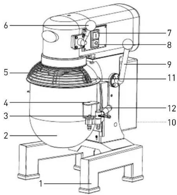
Main parts of the machine
- Rigid stand support
- Bowl
- Bowl clamp (x2)
- Bowl handles (x2)
- Bowl guard
- Speed control lever (3 settings for 3 attachments)
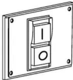
- ON button (GREEN, I)
- STOP button (RED, 0)
- Bowl lift / lower handle
- RESET button (at the rear)
11.Bowl guard handle
12.Bowl cradle
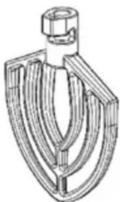
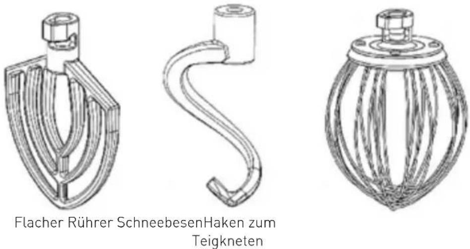
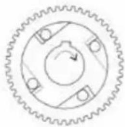
Attachments
natural_image
Technical line drawing of a mechanical component with curved and straight lines (no text or symbols)Flat beater
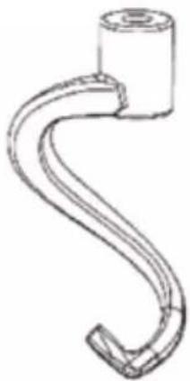
natural_image
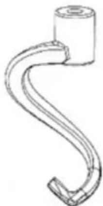
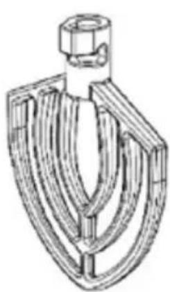
Line drawing of a curved pipe or hook component with a cylindrical head and central hub (no text or symbols)Dough hook

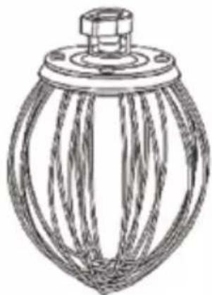
natural_image
Technical line drawing of a mechanical component with radial grooves and a flanged top (no text or symbols)Whisk
Preparations before installation
- Carefully unbolt the machine from the skid using wrench if necessary.
- Remove all protective packaging and wrapping.
-
Check the machine for completeness and transport damages. In case of incomplete delivery (e.g. Whisk, flat beater and dough hook) or damage, contact supplier immediately. DO NOT use the machine. (See ==> Warranty).
-
Clean the machine and attachments before use (See ==> Cleaning and Maintenance).
• Make sure the appliance is completely dry. - Keep the packaging if you intend to store your appliance in the future.
Installation
- Read this manual thoroughly and carefully before installation and operation.
- Ensure the machine is placed in a dry area that have sufficient strength surface to support with no any obstruction during operation nearby.
-
Ensure that the electrical power supply corresponds with the rating label on the machine.
-
There should have adequate space around the machine for the operator to operate. It should be clean and free from obstructions, e.g. Nothing placed on or around the machine, such as scrapers, knives etc.
- Do not wear loose fitting clothing such as scarf, etc and long hair should be tied up and keep away from the moving parts.
CAUTION! Never bypass any safety switch.
Transportation and handling
- Do not move the machine while it is under operation.
-
Unplug the machine, remove the bowl (2) and all attachments (whisk, flat beater or dough hook) when moving the machine.
-
Hold the base of the machine (1) when moving to have better support.
- With at least 2 people or using trolley for assistance to move the machine due to heavy weight.
Special safety features
Attention: This machine has the following 3 safety switches. The machine only be started with all the safety switches are at the proper positions.
- Bowl position safely switch: The machine can be started up once the bowl is positioned at the correct position.
- Bowl guard (5) safety switch: The machine can only be started up once the bowl guard (5) is in the closed position.
- Bowl lift up handle (9) safety switch: The machine can only be started up once the bowl lift up handle (9) is located in the upwards position.
Do not wear loose fitting clothing such as scarf, etc and long hair should be tied up and keep away from the moving parts
Operation
To avoid serious personal injury:
- DO NOT operate the machine without reading the instruction manual.
- ALWAYSSTOP the machine by pressing RED "O" button (8) and unplug from electrical power supply before cleaning, maintenance, repair or changing any attachments.
- ALWAYS keep hands, hair and loose clothing away from the moving parts.

a) About the bowl guard
Note: When bowl guard (5) is open or not properly closed in lock position, the machine will not operate.
- To open the bowl guard (5), hold the bowl guard handle (11) and rotate it clockwise. To close the bowl guard (5), hold the bowl guard handle (11) and rotate it anti-clockwise.
b) Install the bowl (2) to the machine
Note: Install the bowl (2) BEFORE fixing the attachments. Use the supplied bowl (2) only.
-
Lower the bowl by pulling the bowl lift-up lever (9) downwards until it stops. So that the bowl cradle (12) is in a lower position.
-
When the bowl guard handle (11) is lined up at the right side of the machine, the bowl guard (5) is in the is in the rocked position and ready for operation.
-
Place the bowl (2) carefully and slowly using the bowl handles (4) at 2 sides and i) With the locking pin into the hole at the
middle of the bowl cradle (12) and ii) Secure the bowl (2) by pull each bowl clamp (3) forward until the bowl (2) is locked tight.
c) Install different attachments (Flat beater, Dough hook or Whisk) to the machine
Note: It is more convenient and easier to install the attachments prior to adding the ingredients into the bowl (2).
-
Rotate the bowl guard (5) clockwise gently with the bowl guard handle (6), so that it is in the open position.
-
CAUTION! Use excessive force to open or close the bowl guard (5) may damage the safety lock micro switch. Be careful when open or close the bowl guard (5).
d) Pouring and mixing ingredients
Note: Follow the "Mixing ingredients capacity" table in this manual. Overloading will lead to overflow or damage to the machine.
IMPORTANT: Make sure the speed control lever (6) is set at the "dough hook" position.
-
Add all the appropriate ingredients into the bowl (2).
-
Slide the attachments (Flat beater, Dough hook or Whisk) slowly upwards onto the planetary shaft fitting the shaft pin through the slot in the attachments.
-
Rotate the attachments to secure it onto the planetary shaft.
-
Lift upwards the bowl lift lever (9) until the bowl (2) locks into the position.
-
Rotate the bowl guard (5) anti-clockwise and locks into the position.
Attention: The machine will not start if the bowl guard (5) is open / not closed properly or the bowl (2) is at the lower position.
e) Set the speed, attachment & start up the machine
- Select the appropriate speed by lifting or lowering the speed control lever (6). Three fixed speeds are available for different attachments:
Rotation speed Type of ingredient
| Dough hook (Low) | Heavy: Mixing pizza, bread, pasta and |
| Flat beater (Medium) | Medium: 2nd stage of mixing for donut dough, etc. |
| Whisk (High) Light: Whipping cream, egg whites, meringue. | |
IMPORTANT: ALWAYS follow the recommended attachment used and speed setting according to the capacity table and indication next to the speed control lever (6).
ATTENTION: Be careful about the risk of dust and flour escape when slitting of bags of ingredient into bowl (2). Wear protective mask or glasses if necessary.
-
After that, press the GREEN "I" button (7) to switch ON the machine. Press RED "O" button (8) to STOP the machine. The machine will rotate in clockwise direction for item 222843 whereas and anti-clockwise direction for 222836.
-
CAUTION! ALWAYS STOP the machine BEFORE changing speeds. Failure to do so may damage the internal gear construction.
natural_image
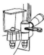
Technical line drawing of a mechanical switch or bracket assembly (no text or symbols)- To change the speed during the operation: a) Press the RED "O" button (8) to STOP the machine. b) Unplug the machine and change the attachment. [See ==> part c]. c) Change the speed by raising or lowering the speed control lever (6) with the correct attachment. d) PresstheGREEN "I" button (7) to restart the machine.
RESET the Hi-limiter (thermal cut-out)
Please note that the RESET button (10) is located at the rear of the machine in order to prevent overheated.
- Unplug the machine from the electrical power outlet first.
-
Let the machine to cool down completely.
-
Press the RESET button (10) of the Hi-limiter (thermal cut-out)
- Then, plug into the electrical power outlet and start up the machine again.
Mixing ingredients capacity
Below table is just a reference about the maximum quantity for making the different food. There are
many factors affecting such as the type of the flour, temperature of water, etc.
| Product Attachment | Max. quantity | ||
| 222836 222843 | |||
| Egg white Whisk 1,0 kg 1,5 kg | |||
| Mashed potato | Flat beater | 2,0 kg 2,5 kg | |
| Meringue (Qty of water) | Whisk | 1,5 litre | 2,0 litre |
| Waffle or pancake batter | Flat beater | 2,5 litres | 3,0 litre |
| Whipped cream | Whisk | 3,5 litres | 4,0 litre |
| Pizza dough (Medium, 50% water) | Dough hook | 2,0 kg 2,5 kg | |
| Pizza dough (Thick, 60% water) Dough hook | 2,5 kg 3,0 kg | ||
| Sponge cake | Whisk 1,5 kg 2,0 kg | ||
| Pie Dough | Flat beater | 2,0 kg 2,5 kg | |
| Bread or Roll Dough (Light/ Medium, 60% water) | Dough hook | Water 1,5 kg/ Flour 2,5 kg | Water 3,0 kg/ Flour 5,0kg |
Cleaning and Maintenance
Attention: Always unplug the appliance from the electrical power outlet and let it cool down completely before cleaning, maintenance, repair & storage.
Cleaning
- Always remove all the attachments before easy cleaning, otherwise it will become stuck on the shaft and difficult to remove later.
- Clean the machine and its attachments thoroughly after each use and ensure all food residues are removed.
- Never immerse the appliance in water or other liquids.
-
Clean the surface with a slightly damp cloth or sponge with some mild soap solution.
-
Never use abrasive sponges, detergents, steel wool or metallic utensils to clean the interior or exterior parts of the appliance.
- DO NOT wash the appliance with water or water-jet. Washing with water can cause leakage and increase the risk of electric shock.
- No any parts or attachments are dishwasher safe.
Recommended cleaning procedure:
| Parts How to clean Frequency | ||
| Bowl Using a sponge or damp cloth | with mild soap and water, rinse, sanitize and dry thoroughly. | Clean after each use |
| Attachments (Dough hook, beater and whisk) | Hand wash using mild soap and water, rinse, sanitize and dry thoroughly. | Clean after each use |
| Bowl guard Hand wash using a sponge | or damp cloth with mild soap and water, rinse, sanitize and dry thoroughly. | Clean after each use |
| Outer surface Wipe with a clean dam | cloth using soap and water, rinse, sanitize and dry. Do not use water jet. | Twice a week |
| Planetary Shaft Wipe with a clean dam | cloth using soap and water, rinse, sanitize and dry. | Clean after each use |
Storage
- Before storage, always make sure the appliance has already been disconnected from the electrical outlet and cooled down completely.
- Store the appliance in a cool, clean and dry place.
Troubleshooting
If the machine does not function properly, please check the below table for the solution. If you are still unable to solve the problem, please contact the supplier/service provider. DO NOT repair yourself.
| Problems Possible causes | Possible solution | |
| Machine do not start running | Bowl guard (5) is not in properly closed position. | Rotate the bowl guard (5) to the right until fully closed properly. |
| Bowl (2) is not raised to the proper location. | Raise the bowl (2) to the correct position by using the level (9). | |
| The power plug is not connected properly. | Check to make sure the power plug is connected properly. | |
| Machine stops during operation | Internal overload activates to prevent overheat. | Press RED, “O” button (8), unplug the machine, leave for cook down completely, press RESET button (10) at the back. |
| Damage or broken transmission belt Check with the supplier | ||
| Machine sound too noisy | Machine is not placed on a horizontal surface. | Adjust the surface or move to another horizontal surface. |
| Bowl (2) is not placed correctly. | Make sure the bowl (2) is placed into the bowl cradle (12) correctly with the guided pins (3). | |
| Attachments not fitted properly. | Remove and install the attachments into position again. | |
| Bowl is overloaded. Reduce ingredients capacity. | ||
| Damaged or worn transmission belt. | Check with the supplier. | |
| Planetary gear needs lack of lubricant. | ||
| Attachments cannot install onto the planetary shaft easily | Lack of lubricant and / or cleaning of the planetary shaft required. | Wipe planetary shaft with a clean damp cloth and lubricate the shaft with mineral oil or grease. |
| Bowl lift / lower handle (9) not operation easily | Lack of lubricant on the bowl slides. | Lubricate bowl slides with mineral oil or grease. |
Technical specification
| Item no. 222836 222843 | |||
| Operating voltage and frequency 220 - 240 V~ 50/60Hz | |||
| Rated input power 600W 1100W | |||
| Net weight (approx.) 53kg 78kg | |||
| Protection class Class I | |||
| Waterproof protection class IP21 | |||
| Rotation speed (r.p.m.) | Dough hook 148 197 | ||
| Flat beater 244 317 | |||
| Whisk 480 462 | |||
| Maximum bowl capacity | 10L | 20L | |
| Maximum amount flour mixing | 2,5 kg | 5,0 kg | |
| Max noise level | < 70 dB (A) | ||
| Outer dimension | 480 x 400 x (H) 630mm | 560 x 500 x (H) 880mm | |
Remark: Technical specification is subjected to change without prior notification.
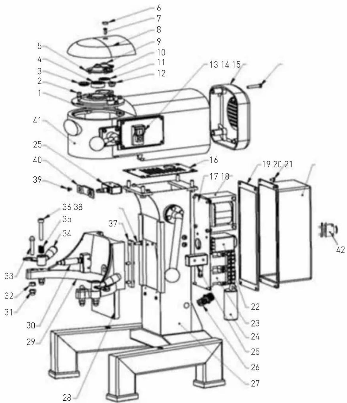
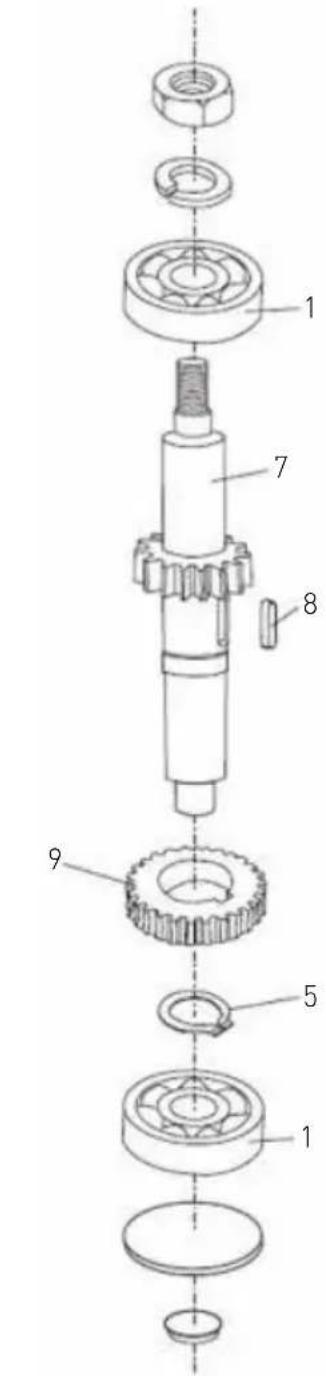
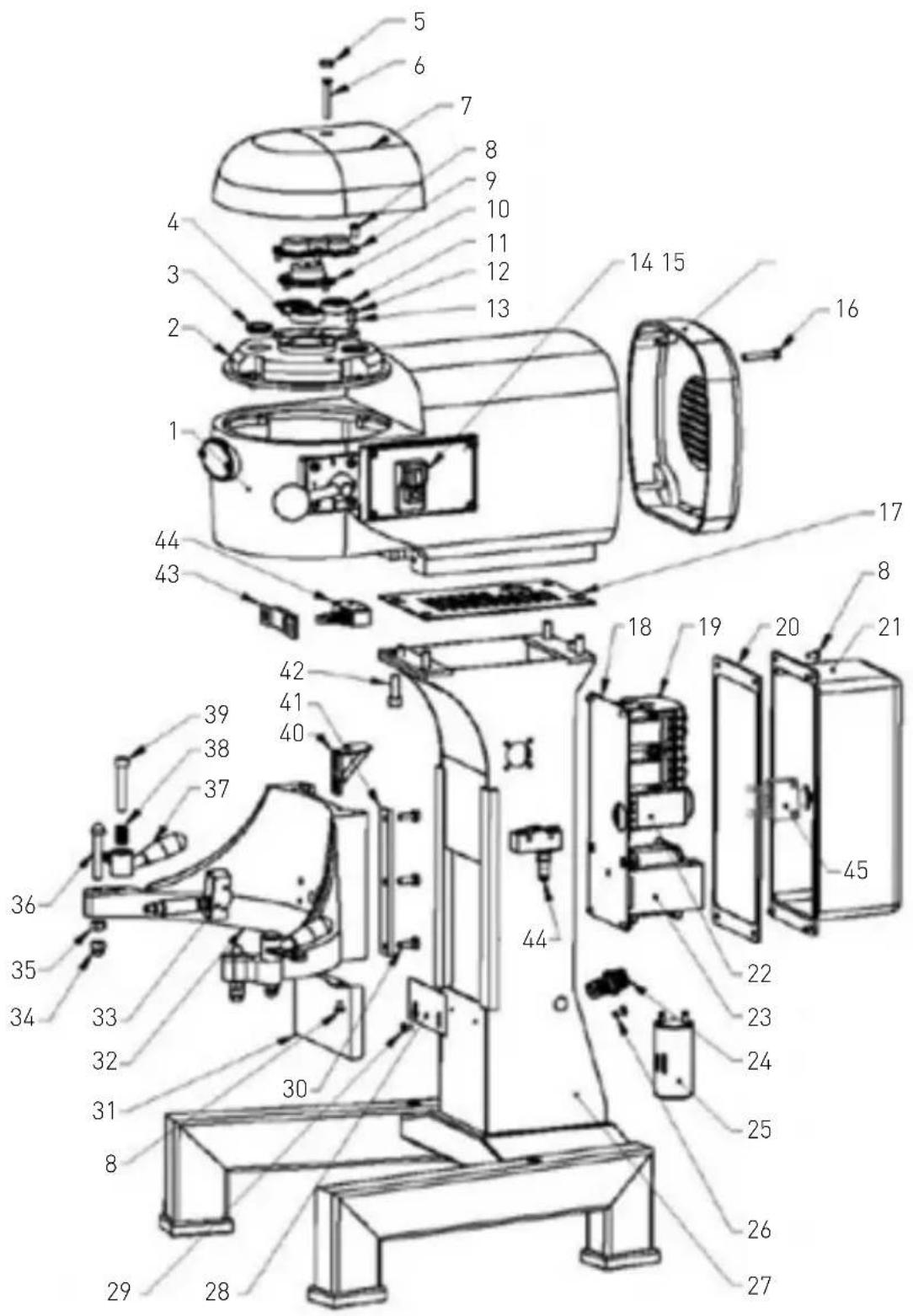
Exploded drawing and part list
Attention: The exploded drawing and part list consists of below parts:
- Transmission gear system at the top, bowl cradle and stand (Figure 1);
- Motor assembly (Figure 4);
- Bowl lift up assembly (Figure 5);
- Axle assembly (Figure 2);
- Bowl guard turning plate and mixing axle (Figure 6);
- Gear axle assembly (Figure 3);
- Speed control assembly (Figure 7)
Figure 1: Transmission gear at the top, bowl cradle and stand
222836:
| Part no. | Part name | Quantity Part no. | Part name | Quantity | ||
| 1 Bearing cover 1 22 Timer relay 1 | ||||||
| 2 Screw (M6X16) 4 23 Relay 2 | ||||||
| 3 Cover 1 24 Capacitor 1 | ||||||
| 4 | Bearing 6202 | 1 | 25 | Microswitch | 3 | |
| 5 | Center cover | 1 | 26 | Cable joint | 1 | |
| 6 Cover 2 27 Upright column | 1 | |||||
| 7 Screw (M5X16) 1 28 | Upright column | board 1 | ||||
| 8 Top cover | 1 29 | Arm complete | 1 | |||
| 9 | Cover | 1 | 30 | Sleeve (for microswitch) | 1 | |
| 10 Screw (M5X8) 5 31 | Cap nut (M8) | 2 | ||||
| 11 Bearing 6001 | 1 32 | Nut (M8) | 4 | |||
| 12 | Cover | 1 | 33 | Bowl's screw | 2 | |
| 13 Power switch 1 34 | Fixed handle | 2 | ||||
| 14 | Rear cover | 1 | 35 | Fixed handle spring | 2 | |
| 15 | Screw (M6X35) 4 36 | Screw (M8X60) | 2 | |||
| 16 | Anti mouse plate | 1 | 37 | Flat clamp | 2 | |
| 17 | Electrical board | 1 | 38 | Screw (M6X16) | 6 | |
| 18 Transformer | 1 39 | Screw (M4X8) | 2 | |||
| 19 | Electric box sealing strips | 1 | 40 | Microswitch rack | 2 | |
| 20 Screw (M5X8) 4 41 | Body | 1 | ||||
| 21 | Electric box | 1 | 42 | Overloaded switch | 1 | |
EN
222843:


| Part no. | Part name | Quantity Part no. | Part name | Quantity | ||
| 1 | Body | 1 24 Cable joint 1 | ||||
| 2 | Bearing cover | 1 25 Capacitor 1 | ||||
| 3 | Cover | 2 | 26 | Copper screw (M5X12) | 1 | |
| 4 | Bearing (6003) | 1 27 | Upright column 1 | |||
| 5 | Cover | 3 | 28 | Upright column board | 1 | |
| 6 | Screw (M6X45) | 1 | 29 | Screw (M4X8) | 2 | |
| 7 | Top cover 1 30 | Screw (M6X16) | 6 | |||
| 8 | Screw (M5X8) | 7 | 31 | Upright column board | 1 | |
| 9 | Cover | 1 | 32 | Arm | 1 | |
| 10 | Center cover | 1 | 33 | Sleeve (for microswitch) | 1 | |
| 11 | Bearing (6201) | 2 | 34 | Cap nut (M8) | 2 | |
| 12 | Screw (M6X14) | 4 | 35 | Nut (M8) | 2 | |
| 13 | Spring washer 6 | 4 | 36 | Bowl's screw | 2 | |
| 14 | Power switch | 1 | 37 | Fixed handle | 2 | |
| 15 | Rear cover | 1 | 38 | Fixed handle spring | 2 | |
| 16 | Screw (M6X35) | 4 | 39 | Screw (M8X60) | 2 | |
| 17 | Anti mouse plate | 1 | 40 | Plastic block | 1 | |
| 18 | Electrical board | 1 | 41 | Flat clamp | 2 | |
| 19 | Relay | 2 | 42 | Screw (M8X25) | 4 | |
| 20 | Electric box sealing strips | 1 | 43 | Microswitch rack | 1 | |
| 21 | Electric box | 1 | 44 | Microswitch | 2 | |
| 22 | Timer relay | 1 | 45 | Overload switch | 1 | |
| 23 | Transformer | 1 | ||||
EN
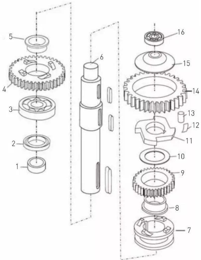
Figure 2: Axle assembly
222836:
natural_image
Pure mechanical gear diagram without any text, numbers, or symbolsFigure 2-1
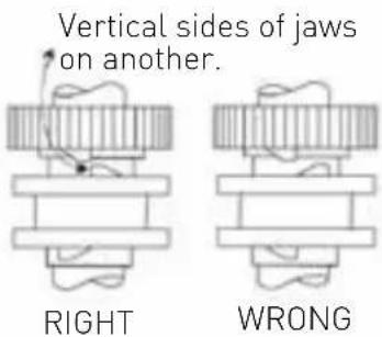
Figure 2-2
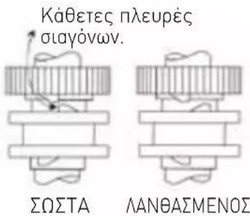
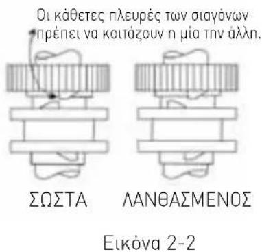
Remark:
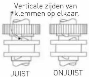
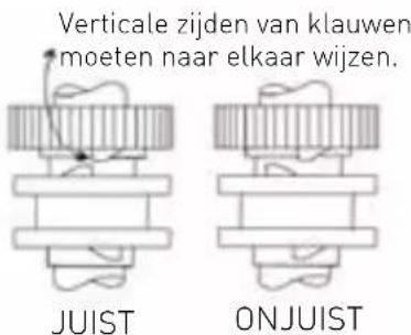
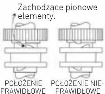
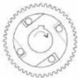
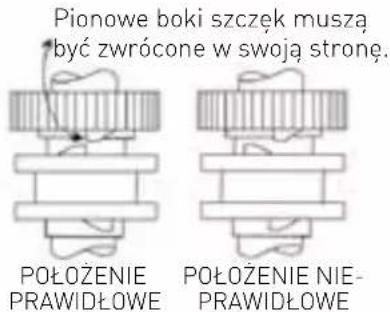
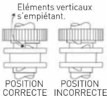
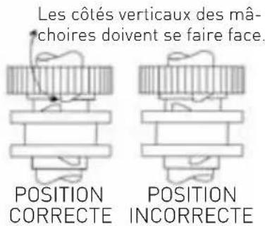
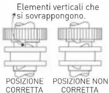
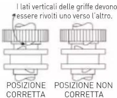
- Be sure to install correct position and lubricate all the pins in figure 2-1.
- Check if oil seal occur after reassembly.
| Part no. | Part name Quantity | |
| 1 Cover | 1 | |
| 2 Oil seal | 1 | |
| 3 Bearing (6204) | 1 | |
| 4 Coupler gear | 1 | |
| 5 bearing | 1 | |
| 6 Central axle | 1 | |
| 7 | Coupler | 1 |
| 8 Bearing | 1 | |
| 9 Small gear ring | 1 | |
| 10 | Divider ring | 1 |
| 11 | Actuator | 1 |
| 12 | Spring | 1 |
| 13 | Roller | 1 |
| 14 | Large gear ring | 1 |
| 15 | Cover 1 | |
| 16 Bearing (6001) | 1 |
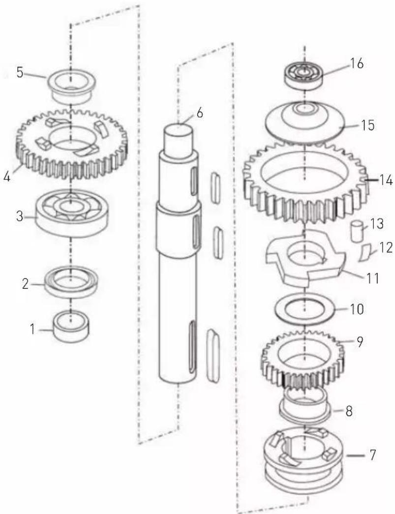
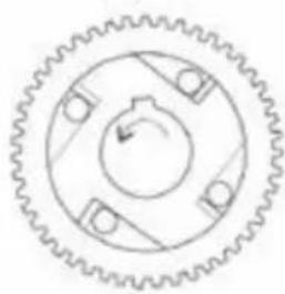
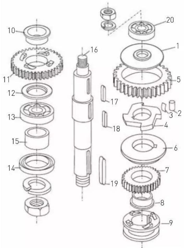
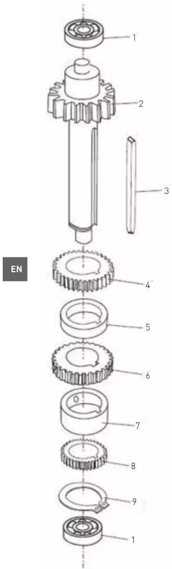
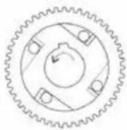
222843:

natural_image
Pure mechanical gear diagram without any text, numbers, or symbolsFigure 2-1
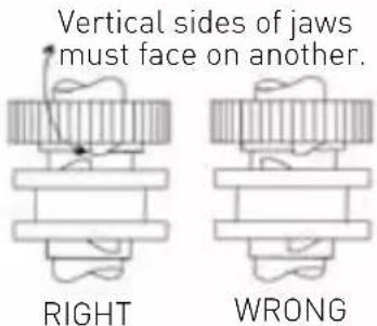
Figure 2-2
Remark:
- Be sure to install correct position and lubricate all the pins in figure 2-1.
- Check if oil seal occur after reassembly.
| Part no. Part name Quantity | ||
| 1 Cover | 1 | |
| 2 Roller | 1 | |
| 3 Spring | 1 | |
| 4 Actuator | 1 | |
| 5 Gear ring | 1 | |
| 6 Divider ring | 1 | |
| 7 | Upper gear | 1 |
| 8 | Bearing ring | 1 |
| 9 Clutch ring | 1 | |
| 10 | Bearing ring | 1 |
| 11 | Lower gear | 1 |
| 12 Ring | 1 | |
| 13 | Bearing (6205) | 1 |
| 14 | Oil seal (30X45X10) | 1 |
| 15 | Stand-off 1 | |
| 16 | Central axle | 1 |
| 17 | Key (6X14) | 1 |
| 18 | Key (5X35) | 1 |
| 19 | Key (6X30) | 1 |
| 20 | Bearing (6003) | 1 |
Figure 3: Gear axle assembly
222836:
| Part no. Part name Quantity | |
| 1 Bearing (6001) 2 | |
| 2 High speed gear axle 1 | |
| 3 Key (5X58) 1 | |
| 4 Top gear 1 | |
| 5 Small stand-off 1 | |
| 6 Gear (lower) 1 | |
| 7 Large stand-off 1 | |
| 8 Bottom gear 1 | |
| 9 Circlip 1 |
Remark: Make sure the keys are all inserted to each gear.
222843:
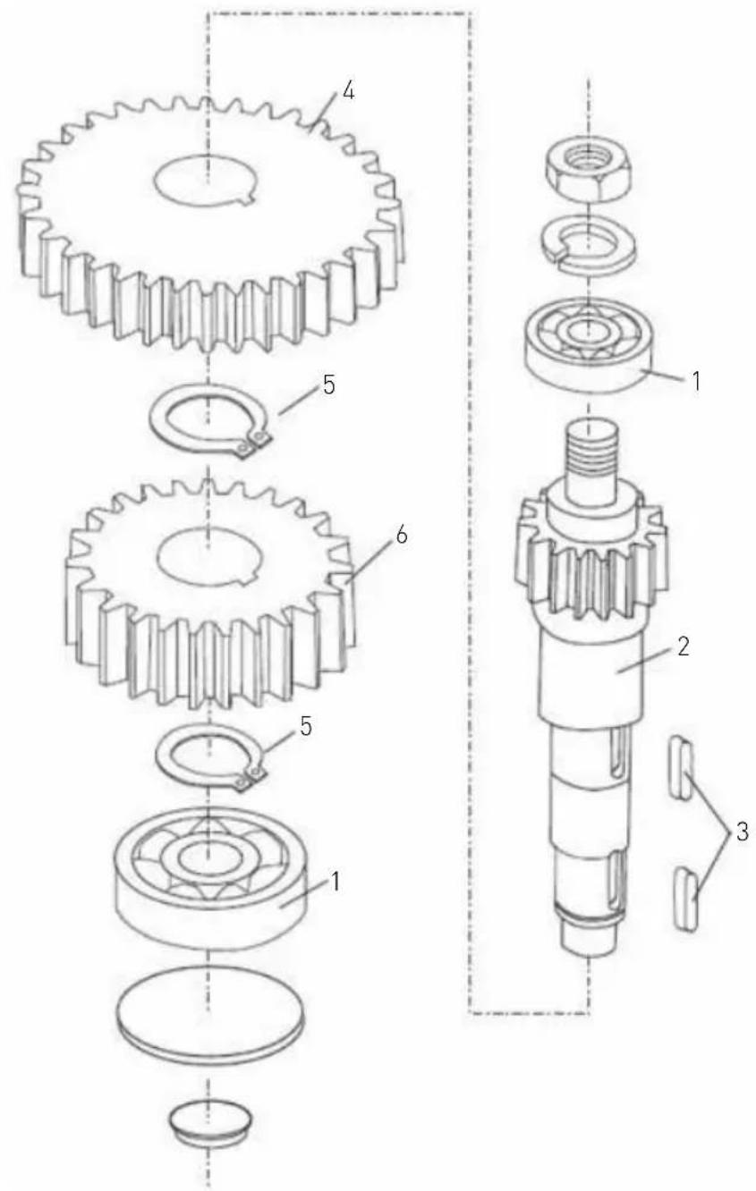
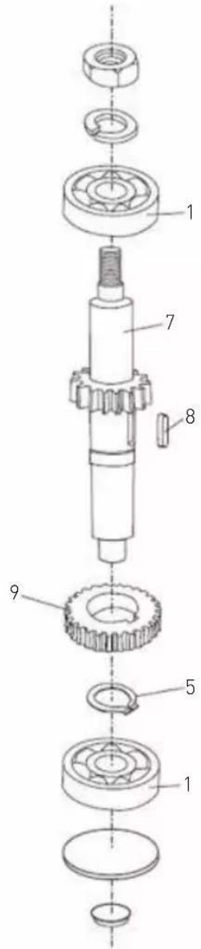
Dual gear axle
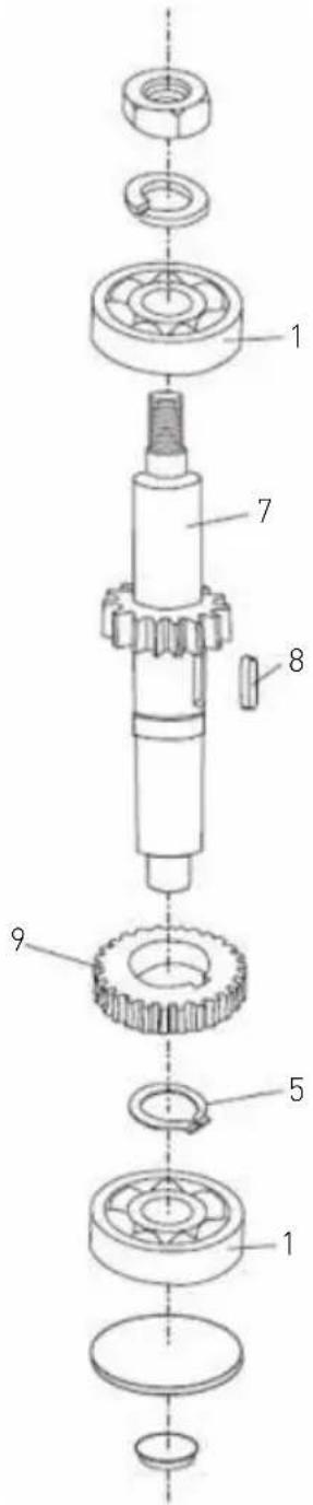
Single gear axle
| Part no. | Part name | Quantity Part no. | Part name | Quantity | ||
| 1 | Bearing (6201) | 4 6 Lower gear 1 | ||||
| 2 | Dual | geared axle 1 | 7 Single geared axle 1 | |||
| 3 | Key (5X11) | 2 8 Key (5X14) | 1 | |||
| 4 | Upper gear | 1 | 9 | Gear | ||
| 5 | Circlip | 3 | ||||
Remark: Make sure the keys are all inserted to each gear.
Figure 4: Motor assembly
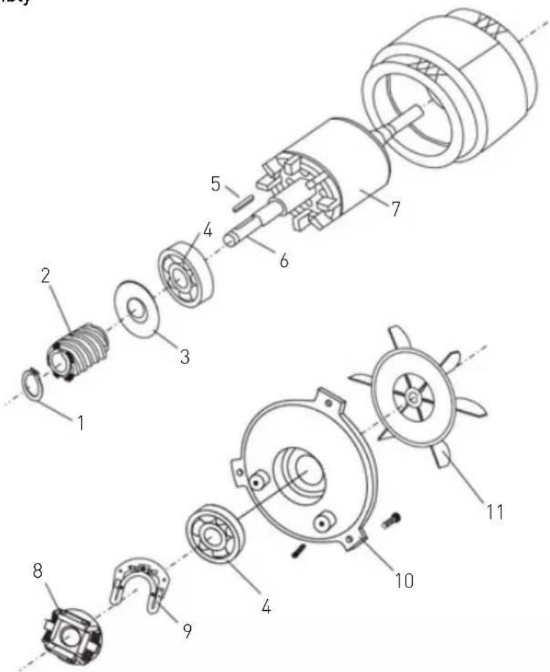
| Part no. | Part name | Quantity Part no. | Part name | Quantity | ||
| 1 Stop ring (222843 only) 1 7 Rotor 1 | ||||||
| 2 Spiral 2 8 Switch 1 | ||||||
| 3 Oil seal 1 9 Plastic switch plate | 1 | |||||
| 4 | Bearing | 1 | 10 | Bearing cover | 1 | |
| 5 | Key (4x22) | 1 | 11 | Fan | 1 | |
| 6 | Axle 1 | |||||
Figure 4-1
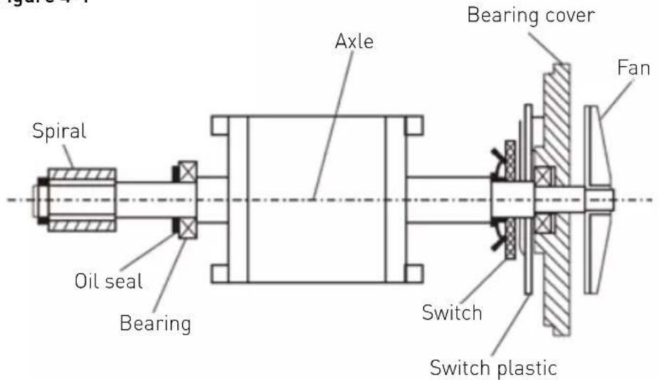
Figure 5: Bowl lift up assembly
EN
| Part no. | Part name | Quantity Part no. | Part name | Quantity | ||
| 1 Nut | (M10) | 3 7 Crank wheel | 1 | |||
| 2 Flat | washer | 2 8 Flange knot | 1 | |||
| 3 | Arm's spring | 1 | 9 | Screw (M6X25) | ||
| 4 Lifting bar | 1 | 10 Key (5x20) | 1 | |||
| 5 | Stop ring | 1 | 11 | Bowl lift handle | ||
| 6 Cotter pin | 12 | Plastic ball | 1 | |||
Figure 6: Turning plate and mixing axle 222836:
| Part no. | Part name | Quantity Part no. | Part name | Quantity | ||
| 1 Inner | gear 1 11 Spring washer 6 5 | |||||
| 2 Screw M4x8 3 12 Ring 1 | ||||||
| 3 Screw M6x20 | 4 13 | Planetary gear 1 | ||||
| 4 Turning plate | 1 14 | Bearing 6203 | 1 | |||
| 5 | Cover | 1 | 15 | Bearing 6003 | 1 | |
| 6 | Spring washer 8 | 1 | 16 | Oil seal (20X40X10) | 1 | |
| 7 Screw M8x25 | 1 17 Key (5X14) | 1 | ||||
| 8 | Bowl guard | 1 | 18 | Mixing axle | 1 | |
| 9 | Plastic cover | 1 | 19 | Back cover of bowl guard | 1 | |
| 10 | Screw M6x16 | 1 | ||||
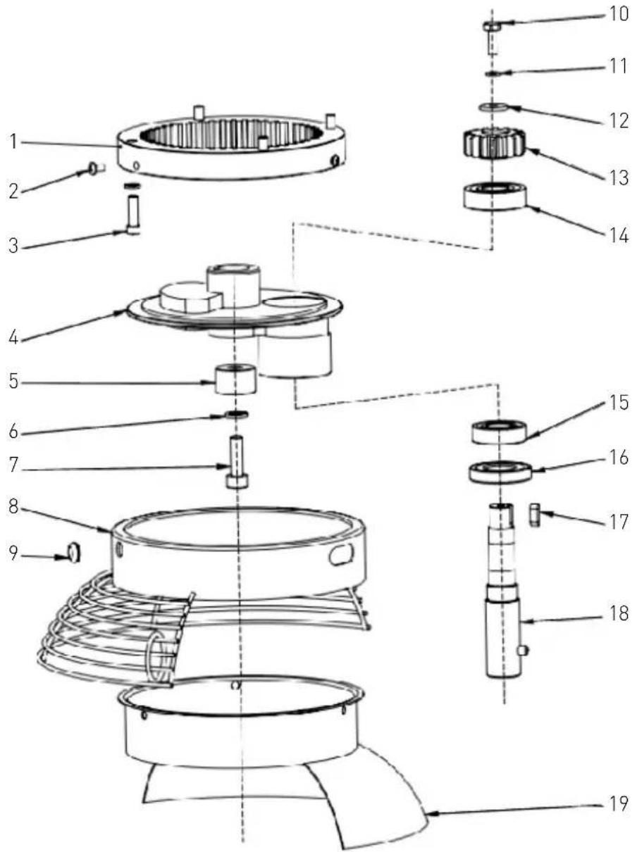
222843:

| Part no. | Part name | Quantity Part no. | Part name | Quantity | ||
| 1 | Inner gear 1 11 Screw M8x16 1 | |||||
| 2 | Screw M5x10 3 12 Spring washer 8 1 | |||||
| 3 | Spring washer 6 6 13 Ring 5 | |||||
| 4 | Screw M6x25 6 14 | Planetary gear 1 | ||||
| 5 | Turning plate | 1 15 Bearing 6203 1 | ||||
| 6 | Spring washer 18 1 16 Bearing 6204 | 1 | ||||
| 7 | Nut (M18) | 1 | 17 | Oil seal (25X50X10) | 1 | |
| 8 | Plastic cover 2 18 Key (5X14) | 1 | ||||
| 9 | Bowl guard | 1 | 19 | Mixing axle | 1 | |
| 10 | Back cover of bowl guard | 1 | ||||
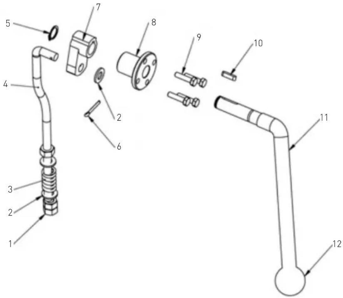
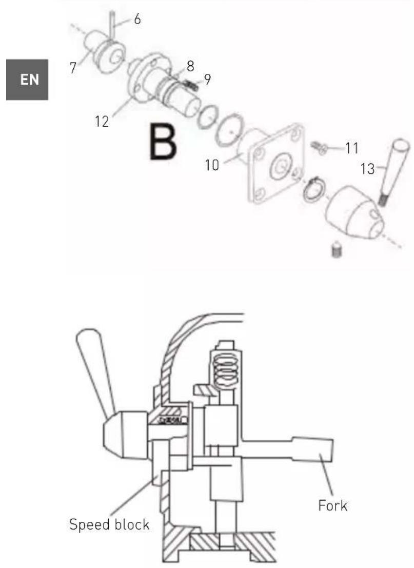
Figure 7: Speed control assembly

| Part no. Part name Quantity | |||
| A | 1 Rod 1 | ||
| 2 Nut 1 | |||
| 3 Spring 1 | |||
| 4 Shaft 1 | |||
| 5 Fork 1 | |||
| B | 6 Pin (3X20) 1 | ||
| 7 Knot 1 | |||
| 8 | Steel ball bearing | 3 | |
| 9 Spring 3 | |||
| 10 | Block cover | 1 | |
| 11 | Screw (M5X10) | 1 | |
| 12 | Shaft 1 | ||
| 13 | Lever | 1 | |
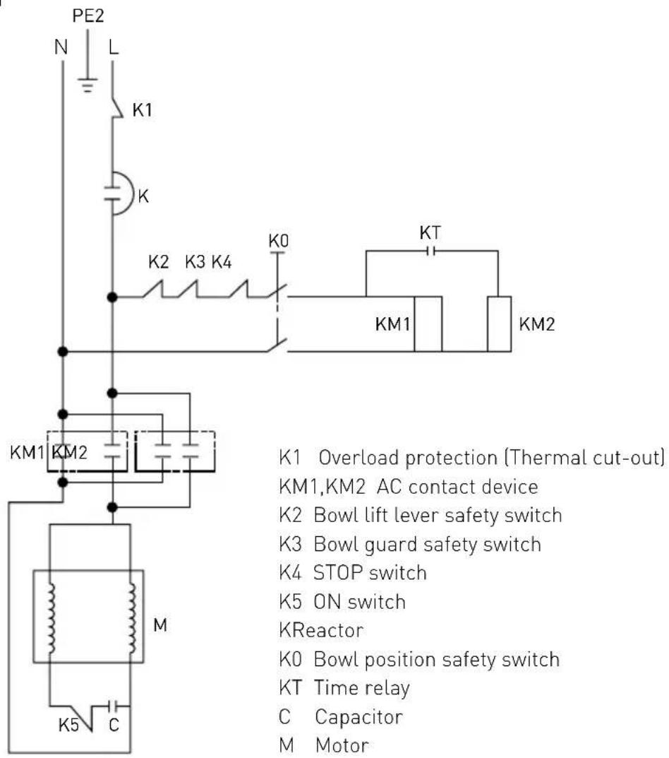
Circuit diagram
Warranty
Any defect affecting the functionality of the appliance which becomes apparent within one year after purchase will be repaired by free repair or replacement provided the appliance has been used and maintained in accordance with the instructions and has not been abused or misused in any way. Your statutory rights are not affected. If the appliance is claimed under warranty, state where and when it was purchased and include proof of purchase (e.g. receipt).
In line with our policy of continuous product development we reserve the right to change the product, packaging and documentation specifications without notice.
Discarding & Environment
When decommissioning the appliance, the product must not be disposed of with other household waste. Instead, it is your responsibility to dispose to your waste equipment by handing it over to a designated collection point. Failure to follow this rule may be penalized in accordance with applicable regulations on waste disposal. The separate collection and recycling of your waste equipment at the time of disposal will help conserve natural resources and ensure that it is recycled in a manner that protects human health and the environment. For more information about where you can drop off your waste for recycling, please contact your local waste collection company. The manufacturers and importers do not take responsibility for recycling, treatment and ecological disposal, either directly or through a public system.
Zubehör
natural_image
Technical line drawing of a mechanical switch or bracket assembly (no text or symbols)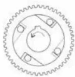
natural_image
Pure mechanical gear diagram without any text, numbers, or symbolsAbb. 2-1
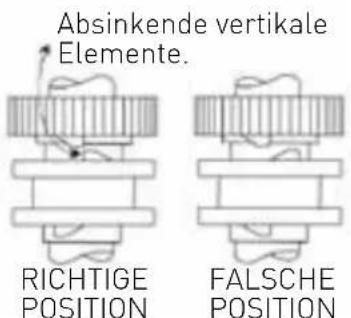
Abb. 2-2
Hinweis:
DE

natural_image
Pure mechanical gear diagram with no text, numbers, or symbolsAbb. 2-1
natural_image
Technical line drawing of a mechanical switch or bracket assembly (no text or symbols)
natural_image
Pure mechanical gear diagram with no text, numbers, or symbolsFiguur 2-1

natural_image
Pure mechanical gear diagram without any text, numbers, or symbolsFiguur 2-1
NL
NL

natural_image
Technical line drawing of a mechanical component with curved and straight sections (no text or symbols)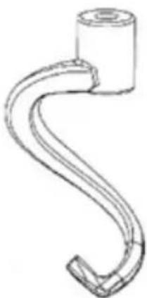
natural_image
Line drawing of a hook-shaped mechanical component (no text or symbols)natural_image
Technical line drawing of a mechanical component with radial grooves and a flanged top (no text or symbols)Przed montażem
natural_image
Technical line drawing of a mechanical switch or bracket assembly (no text or symbols)
natural_image
Pure mechanical gear diagram without any text, numbers, or symbolsRys. 2-1
PL
natural_image
Pure mechanical gear diagram with no text, numbers, or symbolsRys. 2-1
Dual gear axle
Single gear axle
Main parts of the machine
natural_image
Technical line drawing of a mechanical switch or bracket assembly (no text or symbols)
natural_image
Pure mechanical gear diagram without any text, numbers, or symbolsFig. 2-1
FR

natural_image
Pure mechanical gear diagram without any text, numbers, or symbolsFig. 2-1
Axe de transmission double
Axe de transmission simple
natural_image
Technical line drawing of a mechanical switch or bracket assembly (no text or symbols)Recommended cleaning procedure:
natural_image
Pure mechanical gear diagram with no text, numbers, or symbolsFig. 2-1
natural_image
Pure mechanical gear diagram without any text, numbers, or symbolsFig. 2-1
IT
natural_image
Technical line drawing of a mechanical switch or bracket assembly (no text or symbols)
natural_image
Pure mechanical gear diagram without any text, numbers, or symbolsFigura 2-1
RO

natural_image
Pure mechanical gear diagram with no text, numbers, or symbolsFigura 2-1
| Piesă nr. | Denumirea piesei Cantitatea | |
| 1 | Rulment (6001) 2 | |
| 2 | Ax mecanism de mare viteză 1 | |
| 3 | Cheie (5X58) 1 | |
| 4 | Mecanism superior 1 | |
| 5 | Separator mic 1 | |
| 6 | Mecanism inferior 1 | |
| 7 | Separator mare 1 | |
| 8 | Mecanism inferior 1 | |
| 9 | Inel elastic 1 |
RO
natural_image
Technical line drawing of a mechanical switch or bracket assembly (no text or symbols)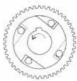
natural_image
Pure mechanical gear diagram with no text, numbers, or symbolsРис. 2-1
RU
natural_image
Pure mechanical gear diagram without any text, numbers, or symbolsРис. 2-1
natural_image
Technical line drawing of a mechanical component with curved and straight sections (no text or symbols)Αναδευτήρας
natural_image
Schematic line drawing of a hook-shaped pipe or hook component (no text or symbols)Γάντος ζύμης
natural_image
Line drawing of a mechanical component with radial grooves and a central hub (no text or symbols)Χτυπητήρι
natural_image
Technical line drawing of a mechanical switch or bracket assembly (no text or symbols)
natural_image
Pure mechanical gear diagram without any text, numbers, or symbolsEikóva 2-1
GR

natural_image
Pure mechanical gear diagram without any text, numbers, or symbolsEikóva 2-1
Nastavci
natural_image
Technical line drawing of a mechanical clamp or bracket with no visible text or symbols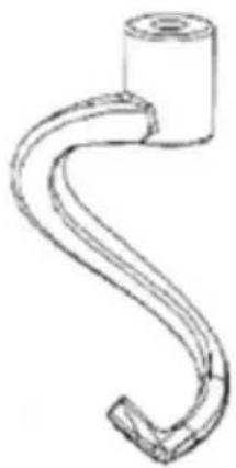
natural_image
Simple line drawing of a curved pipe or hook with a cylindrical end (no text or symbols)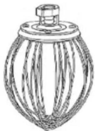
natural_image
Line drawing of a mechanical component with radial grooves and a central hub (no text or symbols)WhiskGruba kukaRavno kazalište
natural_image
Technical line drawing of a mechanical switch or bracket assembly (no text or symbols)| Dio br. Naziv dijela Količina Dio br. Naziv dijela Količina | |||||
| 1 Poklopac ležaja 1 22 Relej tajmera 1 | |||||
| 2 Vijak (M6X16) 4 23 Relej 2 | |||||
| 3 | Poklopac | 1 | 24 | Kapacitor | 1 |
| 4 | Ležaj 6202 | 1 | 25 | Microswitch | 3 |
| 5 | Središnji poklopac | 1 | 26 | Spoj kabela | 1 |
| 6 | Poklopac | 2 27 Uspravni stupac 1 | |||
| 7 Vijak (M5X16) 1 28 Upright ploča stupaca | 1 | ||||
| 8 Gornji poklopac 1 29 Dovršena ruka | 1 | ||||
| 9 | Poklopac | 1 | 30 | Rukavac (za mikroprekidač) | 1 |
| 10 Vijak (M5X8) 5 31 Kapa matica (M8) 2 | |||||
| 11 | Ležaj 6001 | 1 32 Matica (M8) | 4 | ||
| 12 | Poklopac | 1 | 33 | Vijak posude | 2 |
| 13 | Prekidač napajanja | 1 | 34 | Fiksna ručka | 2 |
| 14 | Stražnji poklopac | 1 | 35 | Opruga s fiksnom drškom | 2 |
| 15 | Vijak (M6X35) 4 36 | Vijak (M8X60) 2 | |||
| 16 | Antimišna pločica | 1 | 37 | Ravna stezaljka | 2 |
| 17 | Električna ploča | 1 | 38 | Vijak (M6X16) | 6 |
| 18 Transformator 1 39 | Vijak (M4X8) 2 | ||||
| 19 | Električne trake za brtvlje-nje kutije | 1 40 | Microswitch stalak 2 | ||
| 20 Vijak (M5X8) 4 41 | Tijelo | 1 | |||
| 21 | Električna kutija | 1 | 42 | Preopterećeni prekidač | 1 |
HR
222843:
| Dio br. Naziv dijela Količina Dio br. Naziv dijela Količina | |||||
| 1 Tijelo 1 24 Spoj kabela 1 | |||||
| 2 Poklopac ležaja 1 25 Kapacitor 1 | |||||
| 3 Poklopac 2 26 | Bakreni vijak (M5X12) 1 | ||||
| 4 Ležaj (6003) 1 27 Uspravni stupac | 1 | ||||
| 5 Poklopac 3 28 | Upright ploča stupaca 1 | ||||
| 6 | Vijak (M6X45) | 1 | 29 | Vijak (M4X8) | 2 |
| 7 Gornji poklopac 1 30 Vijak (M6X16) 6 | |||||
| 8 | Vijak (M5X8) | 7 | 31 | Upright ploča stupaca | 1 |
| 9 Poklopac 1 32 Ruka | 1 | ||||
| 10 | Središnji poklopac | 1 | 33 | Rukavac (za mikroprekidač) | 1 |
| 11 | Ležaj (6201) | 2 | 34 | Kapa matica (M8) | 2 |
| 12 | Vijak (M6X14) | 4 35 Matica (M8) 2 | |||
| 13 | Opružna podloška 6 | 4 | 36 | Vijak posude | 2 |
| 14 | Prekidač napajanja | 1 | 37 | Fiksna ručka | 2 |
| 15 | Stražnji poklopac | 1 | 38 | Opruga s fiksnom drškom | 2 |
| 16 | Vijak (M6X35) | 4 | 39 | Vijak (M8X60) | 2 |
| 17 | Antimišna pločica | 1 | 40 | Plastični blok | 1 |
| 18 | Električna ploča | 1 | 41 | Ravna stezaljka | 2 |
| 19 | Relej 2 42 | Vijak (M8X25) 4 | |||
| 20 | Električne trake za brtvlje-nje kutije | 1 43 | Microswitch stalak 1 | ||
| 21 | Električna kutija | 1 | 44 | Microswitch | 2 |
| 22 | Relej tajmera | 1 | 45 | Prekidač preopterećenja | 1 |
| 23 Transformator 1 | |||||
HR
Slika 2: Sklop osovine
222836:

natural_image
Pure mechanical gear diagram with no text, numbers, or symbols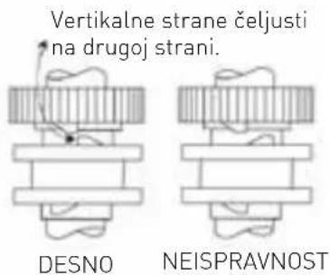
Slika 2-1 Slika 2-2
Napomena:

natural_image
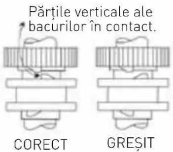
Pure mechanical gear diagram without any text, numbers, or symbolsVertikalne strane čeljusti moraju biti okrenute na drugu stranu.
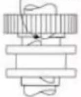
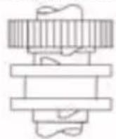
DESNO
NEISPRAVNOST
Slika 2-1 Slika 2-2
Napomena:
Dvostruka osovina zupčanika

Jednostruka osovina zupčanika
| Dio br. Naziv dijela Količina Dio br. Naziv dijela Količina | |||||
| 1 Ležaj (6201) 4 6 Donja brzina 1 | |||||
| 2 | Dvostruka osovina s zup-čanikom | 1 | 7 | Jednostruka osovina s zup-čanikom | 1 |
| 3 Ključ (5X11) 2 8 Ključ (5X14) 1 | |||||
| 4 Gornja brzina 1 9 Gear | 1 | ||||
| 5 | Circlip | 3 | |||
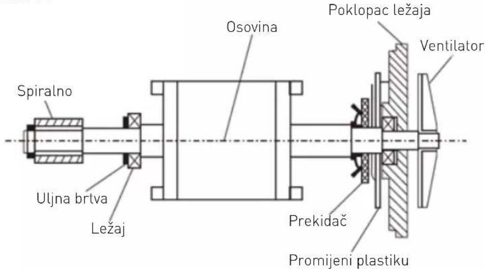
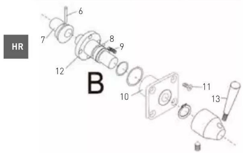
| Dio br. | Naziv dijela Količina Dio br. Naziv dijela Količina | ||||
| 1 | Prsten za zaustavljanje[samo 222843] | 1 7 Rotor 1 | |||
| 2 Spiralno 2 8 Prekidač 1 | |||||
| 3 Uljna brtva 1 9 Plastična preklopna ploča | 1 | ||||
| 4 | Ležaj | 1 | 10 | Poklopac ležaja | 1 |
| 5 | Ključ (4x22) | 1 | 11 | Ventilator | 1 |
| 6 Osovina | 1 | ||||
Slika 4-1
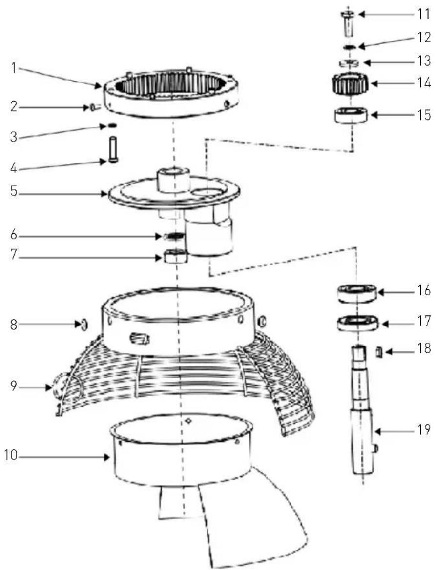
Slika 5: Sklop za podizanje posude

HR
| Dio br. Naziv dijela Količina Dio br. Naziv dijela Količina | |||||
| 1 Unutarnji zupčanik 1 11 Opružna podloška 6 5 | |||||
| 2 Vijak M4x8 3 12 Prsten 1 | |||||
| 3 Vijak M6x20 4 13 Planetarna oprema | 1 | ||||
| 4 Ploča za okretanje 1 14 Ležaj 6203 | 1 | ||||
| 5 | Poklopac | 1 | 15 | Ležaj 6003 | 1 |
| 6 | Opružna podloška 8 | 1 | 16 | Uljna brtva (20X40X10) | 1 |
| 7 Vijak M8x25 1 17 Ključ (5X14) | 1 | ||||
| 8 | Zaštita posude | 1 | 18 | Osovina za miješanje | 1 |
| 9 Plastični poklopac 1 19 | Stražnji poklopac štitnika posude | 1 | |||
| 10 | Vijak M6x16 1 | ||||
222843:
| Dio br. Naziv dijela Količina Dio br. Naziv dijela Količina | |||||
| 1 Unutarnji zupčanik 1 11 Vijak M8x16 1 | |||||
| 2 Vijak | M5x10 3 12 Opružna podloška 8 1 | ||||
| 3 Opružna podloška 6 6 13 Prsten | 5 | ||||
| 4 Vijak | M6x25 6 14 | Planetarna oprema | 1 | ||
| 5 Ploča za okretanje | 1 15 | Ležaj 6203 | 1 | ||
| 6 | Opružna podloška 18 | 1 | 16 | Ležaj 6204 | 1 |
| 7 | Matica (M18) | 1 | 17 | Uljna brtva (25X50X10) | 1 |
| 8 Plastični poklopac | 2 18 | Ključ (5X14) | 1 | ||
| 9 | Zaštita posude | 1 | 19 | Osovina za miješanje | 1 |
| 10 | Stražnji poklopac štitnika posude | 1 | |||
Slika 7: Sklop za kontrolu brzine
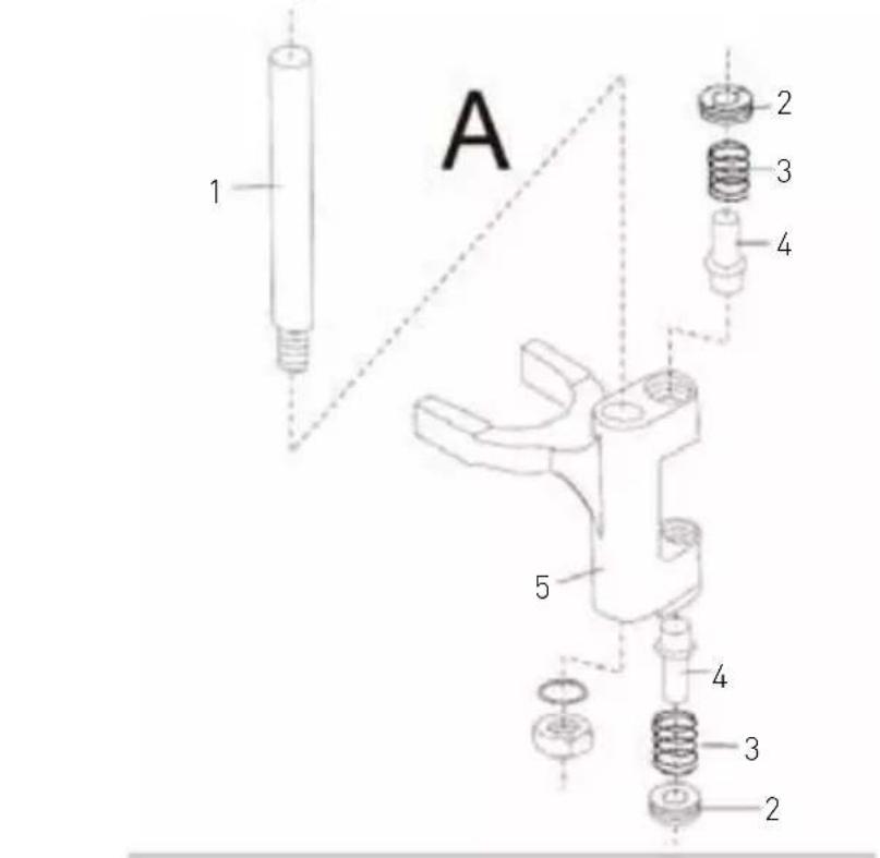
| Dio br. Naziv dijela Količina | |||
| A | 1 Šipka 1 | ||
| 2 Matica 1 | |||
| 3 Proljeće 1 | |||
| 4 Osovina 1 | |||
| 5 Vilica 1 | |||
| B | 6 Pin (3X20) 1 | ||
| 7 Knot 1 | |||
| 8 | Čelični kuglični ležaj | 3 | |
| 9 Proljeće 3 | |||
| 10 | Poklopac bloka 1 | ||
| 11 | Vijak (M5X10) | 1 | |
| 12 | Osovina 1 | ||
| 13 Ručica 1 | |||

Dijagram kruga
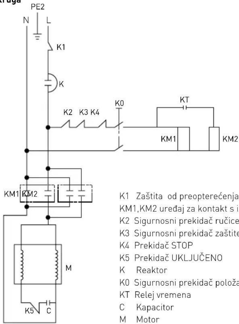
natural_image
Technical line drawing of a mechanical switch or bracket assembly (no text or symbols)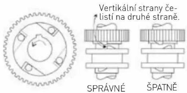
CZ
natural_image
Pure mechanical gear diagram with no text, numbers, or symbols
natural_image
Technical line drawing of a mechanical switch or bracket assembly (no text or symbols)
natural_image
Pure mechanical gear diagram with no text, numbers, or symbolsnatural_image
Pure mechanical gear diagram without any text, numbers, or symbolsKétfokozatú tengely

Egyfokozatú tengely
HU
HENDI Romania S.R.L.
39100 Bolzano (BZ), Italy
Tel: +39 800 727 438
Email: office.italy@hendi.eu
HENDI HK Ltd.
1208, 12/F Exchange Tower
33 Wang Chiu Road, Kowloon Bay, Hong Kong
Tel: +852 2154 2618
Email: info-hk@hendi.eu
Find HENDI on internet:
www.hendi.com
www.facebook.com/HendiToolsforChefs
https://www.linkedin.com/company/hendi-tools-for-chefs/
www.youtube.com/HendiEquipment
GB: Changes, printing and typesetting errors reserved.


- Safety regulations
- Special Safety Regulations
- Intended use
- Grounding installation
- Main parts of the machine
- Attachments
- Preparations before installation
- Installation
- Transportation and handling
- Special safety features
- Operation
- a) About the bowl guard
- Note: When bowl guard (5) is open or not properly closed in lock position, the machine will not operate.
- b) Install the bowl (2) to the machine
- c) Install different attachments (Flat beater, Dough hook or Whisk) to the machine
- d) Pouring and mixing ingredients
- e) Set the speed, attachment & start up the machine
- RESET the Hi-limiter (thermal cut-out)
- Mixing ingredients capacity
- Cleaning and Maintenance
- Cleaning
- Storage
- Troubleshooting
- Exploded drawing and part list
- Remark:
- Circuit diagram
- Warranty
- Discarding & Environment
- Hinweis:
- Przed montażem
- Nastavci
- Napomena:
- Dijagram kruga
- HENDI Romania S.R.L.
- HENDI HK Ltd.
- Find HENDI on internet:
Brand : Hendi
Model : 222843
Category : Food Processor