PowerConnect JEX4500 - Router DELL - Free user manual and instructions
Find the device manual for free PowerConnect JEX4500 DELL in PDF.
| Product Type | Ethernet switch with routing functions |
| Brand | Dell |
| Model | PowerConnect JEX4500 |
| Maximum weight (with two power supplies) | 40 lb (18 kg) |
| Weight (one power supply) | 37 lb (17 kg) |
| Number of power supplies | 2 (redundant) |
| Power supply | Alternating current (AC) |
| Network ports | 48 ports (even numbers 0-38 top, odd bottom) |
| Management port | 1 MGMT port (RJ-45, me0) |
| Console port | 1 console port |
| USB port | 1 USB port |
| Uplink modules | Slots for optional modules (not detailed) |
| Display | LCD screen with Menu and Enter keys |
| Main functions | Virtual Chassis (J-EX4500 and mixed J-EX4200), J-Web, EZSetup, CLI, out-of-band management via VME |
| Operating system | Junos (Junos OS) |
| Rack mounting | 19 inches, mounting brackets provided (front or rear, EXHAUST or INTAKE airflow) |
| Safety | Mandatory grounding, installation by qualified personnel, disconnect during thunderstorms |
| Included accessories | Mounting brackets, screws, grounding cable with lug, Ethernet cable |
Frequently Asked Questions - PowerConnect JEX4500 DELL
User questions about PowerConnect JEX4500 DELL
0 question about this device. Answer the ones you know or ask your own.
Ask a new question about this device
Download the instructions for your Router in PDF format for free! Find your manual PowerConnect JEX4500 - DELL and take your electronic device back in hand. On this page are published all the documents necessary for the use of your device. PowerConnect JEX4500 by DELL.
USER MANUAL PowerConnect JEX4500 DELL
Dell PowerConnect J-Series J-EX4500 Ethernet Switch Quick Start
To install and configure a Dell PowerConnect J-Series J-EX4500 Ethernet Switch (regulatory model number EX4500) on a two-post 19-inch rack or cabinet, you need:
- Two mounting brackets and 20 mounting screws (provided)
• A Phillips (+) screwdriver, number 2 - 8 rack-mount screws—and 8 cage nuts and washers if your rack requires them—of the appropriate size and type to secure the chassis to your rack or cabinet (provided)
- A flat-blade (-) screwdriver if you are installing the switch in a rack with square, nonthreaded holes
- A jumper cable and cord retainer for each power supply (provided)
- For Virtual Chassis connection, one or more Virtual Chassis cables and cable connector retainers
- A grounding cable—14 AWG (2 mm²), minimum 90°C wire—with appropriate grounding lug attached by a licensed electrician, for grounding points 0.625 in. (15.86 mm) apart
- Two 10-32 x.1/4-in. screws with split washers to secure the grounding lug to the switch
- An Ethernet cable with an RJ-45 connector attached (provided)
• A management host with an Ethernet port, such as a PC or laptop
NOTE: For four-post rack or cabinet installation and other information, see the Dell PowerConnect J-EX4500 switch documentation at http://www.support.dell.com/manuals.
Part 1: Install a Power Supply in the Switch (If It Is Not Installed)
-
Ensure that you have the correct power supply:
-
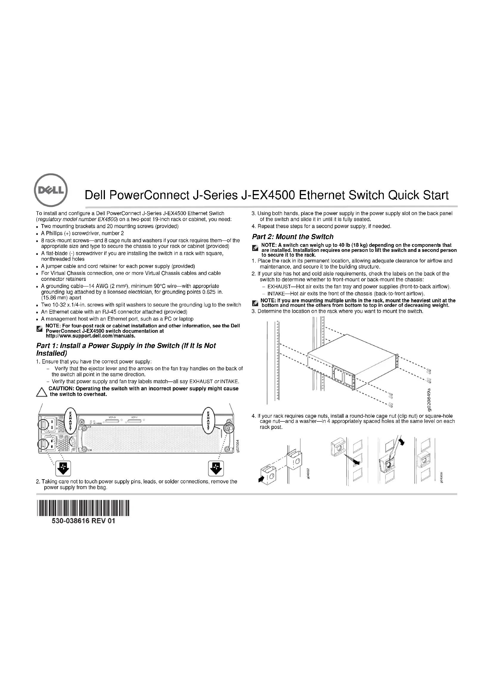
Verify that the ejector lever and the arrows on the fan tray handles on the back of the switch all point in the same direction.
- Verify that power supply and fan tray labels match—all say EXHAUST or INTAKE.
CAUTION: Operating the switch with an incorrect power supply might cause the switch to overheat.
text_image
EXHAUST VCP.0 VCP.1 EXHAUST 2021064-
Taking care not to touch power supply pins, leads, or solder connections, remove the power supply from the bag.
-
Using both hands, place the power supply in the power supply slot on the back panel of the switch and slide it in until it is fully seated.
- Repeat these steps for a second power supply, if needed.
Part 2: Mount the Switch
NOTE: A switch can weigh up to 40 lb (18 kg) depending on the components that are installed. Installation requires one person to lift the switch and a second person to secure it to the rack.
- Place the rack in its permanent location, allowing adequate clearance for airflow and maintenance, and secure it to the building structure.
- If your site has hot and cold aisle requirements, check the labels on the back of the switch to determine whether to front-mount or back-mount the chassis:
- EXHAUST—Hot air exits the fan tray and power supplies (front-to-back airflow). - INTAKE—Hot air exits the front of the chassis (back-to-front airflow).
NOTE: If you are mounting multiple units in the rack, mount the heaviest unit at the bottom and mount the others from bottom to top in order of decreasing weight.
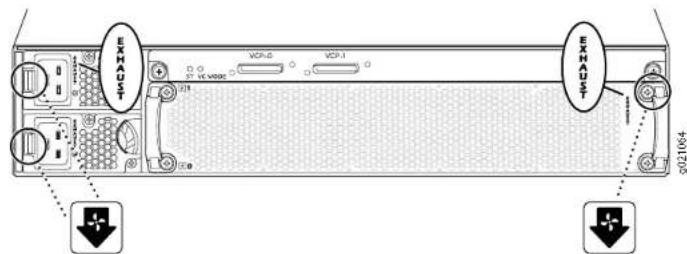
3. Determine the location on the rack where you want to mount the switch.
natural_image
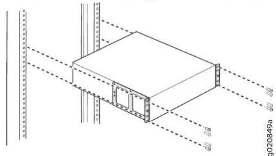
Technical line drawing of a rectangular structural component with dashed alignment lines and dimension labels (no readable text or symbols)- If your rack requires cage nuts, install a round-hole cage nut (clip nut) or square-hole cage nut—and a washer—in 4 appropriately spaced holes at the same level on each rack post.
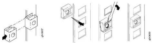
text_image
Technical diagram showing four different installation or mounting configurations with labeled components and directional arrows indicating assembly or movement.
530-038616 REV 01
Dell PowerConnect J-Series J-EX4500 Ethernet Switch Quick Start—page 2
- Place the switch on a flat, stable surface.
- Align the mounting brackets along the front or back of the chassis side panels depending on whether you are front-mounting or back-mounting the switch.
- Attach the mounting brackets to the chassis with the mounting screws, and tighten the screws.

text_image
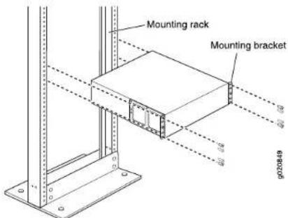
Technical diagram of an electronic device with labeled components and directional arrows indicating assembly or measurement.- Have one person grasp both sides of the switch to lift it and position it in the rack, aligning the mounting bracket holes with the holes in the rack posts so that the bottom hole in each bracket lines up with a hole at the same level in each rack post.
text_image
Mounting rack Mounting bracket p020449- Have a second person install a rack-mount screw in each hole to secure the switch to the rack.
- After ensuring that the chassis is level, tighten the screws.
Part 3: Connect the Switch to Earth Ground
- Connect one end of the grounding cable to a proper earth ground, such as the rack in which the switch is mounted.
- Place the grounding lug attached to the grounding cable over the protective earthing terminal on the left side of the chassis (toward the back), and secure the lug to the terminal by tightening the screws and washers.

text_image
Grounding lug Screw (with split washer)Part 4: Attach the Jumper Cable to the Power Supply
- Squeeze the two sides of the jumper cable retainer clip, and insert the L-shaped ends of the wire clip into the holes in the bracket on each side of the AC appliance inlet.

text_image
Retainer clip Adjustment nut Tighten adjustment nut- Insert the coupler end of the jumper cable into the AC appliance inlet.
- Push the retainer clip toward the cord until the cord slides into the slot in the adjustment nut.
- Turn the nut until it is tight against the base of the coupler and the slot in the nut is turned 90° from the top of the switch.
- If the AC power source outlet has a power switch, set it to the OFF (0) position.
- Repeat these steps for a second power supply, if needed.
NOTE: Do not power on the switch at this time. You will do so as part of initial configuration. Power-on timing is particularly important for Virtual Chassis configurations because power-on order helps determine mastership.
Part 5: Determine How You Will Operate Your J-EX4500 Switch
- Standalone—To operate your J-EX4500 as a standalone switch, go to Part 6 on page 3 to connect power and perform initial configuration.
- J-EX4500 Virtual Chassis—To create a Virtual Chassis with another J-EX4500 switch, go to Part 7 on page 4.
- Mixed Virtual Chassis—To create a Virtual Chassis with up to eight J-EX4200 switches and up to one other J-EX4500 switch, go to Part 8 on page 4.
Dell PowerConnect J-Series J-EX4500 Ethernet Switch Quick Start—page 3
CAUTION: Although J-EX4500 switches are shipped with the Virtual Chassis module installed, Virtual Chassis operation requires preparation in addition to hardware connection. Do not physically connect multiple switches in a Virtual Chassis before reading the appropriate instructions.
You can also add your J-EX4500 switch to an existing J-EX4200 Virtual Chassis or mixed J-EX4200 and J-EX4500 Virtual Chassis. For instructions, see the Dell PowerConnect J-EX Series documentation at http://www.support.dell.com/manuals.
NOTE: You can configure and manage a standalone J-EX4500 switch with the J-Web interface, but the J-Web interface does not support configuration and management of a J-EX4500 Virtual Chassis or a mixed Virtual Chassis.
Part 6: Power On the Switch and Perform Initial Configuration
NOTE: If your switch will be part of a J-EX4500 Virtual Chassis, go first to Part 7 on page 4. For a mixed Virtual Chassis, go first to Part 8 on page 4.
Read through the following steps before you begin the configuration:
- Insert the jumper cable plug into the power source outlet on the switch.
- If the AC power source outlet has a power switch, set it to the ON (I) position.
- Verify that the LED on each power supply glows steadily green for normal operation.
- Enable a DHCP client on the management PC or laptop you will connect to the switch so that the management device can obtain an IP address dynamically.
- Become familiar with the LCD panel, Menu and Enter buttons, and status LEDs.
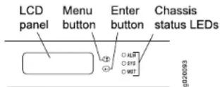
The LCD panel displays a count-down timer when the switch is in initial setup mode. You must complete the initial configuration using EZSetup within 10 minutes. After 10 minutes, the switch exits EZSetup and reverts to the factory default configuration, and the PC or laptop loses connectivity to the switch
-
Transition the switch into initial setup mode:
-
Press the Menu button until you see MAINTENANCE MENU. Then press the Enter button.
- Press the Menu button until you see EZSetup. Then press the Enter button. If EZSetup does not appear as an option in the menu, select Factory Default to return the switch to the factory default configuration. EZSetup is displayed in the menu only when the switch is set to the factory default configuration.
-
Press the Enter button to confirm setup and continue with EZSetup.
-
Connect the Ethernet cable from the Ethernet port on the PC or laptop to the MGMT port (me0) on the front panel of the switch.
The me0 interface (the port labeled MGMT) is configured as the DHCP server with the default IP address 192.168.1.1. The switch can assign an IP address to the management PC or laptop in the range 192.168.1.2 through 192.168.1.253.
- From the PC or laptop, open a Web browser, type http://192.168.1.1 in the address field, and press the Enter key.
- On the J-Web Login page, enter root as the username, leave the password field blank, and click Login.
- On the Introduction page, click Next.
NOTE: If you are configuring a Virtual Chassis master switch, the values you enter in Steps 11 through 14 are applied to all Virtual Chassis members.
- On the Basic Settings page, enter the hostname, enter and reenter a password, specify the time zone, and synchronize the switch date and time settings with the management PC or laptop—or set them manually—and click Next.
- On the Management Options page, select Out-of-band Management—Configure management port to configure the management interface, and click Next.
- Specify the IP address and default gateway for the management interface.
- Click Next. On the Manage Access page, you may select options to enable Telnet, SSH, and SNMP services. For SNMP, you can configure the read community, location, and contact.
- Click Next. The Summary page displays the settings you have selected.
- Click Finish. The configuration is committed as the active switch configuration.
NOTE: If connectivity between the management PC or laptop and the switch is lost, reconnect by entering the appropriate commands on the PC or laptop to release and renew the IP address—or remove and reinsert the Ethernet cable. - For standalone operation only, log in to the command-line interface (CLI) and set the mode to intraconnect:
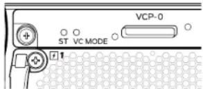
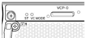
user@switch> request chassis pic-mode intraconnect For standalone operation only, verify that the green ST (status) LED on the Virtual Chassis module is on steadily and that the VC MODE LED is off.
- Observe the amber ALM (alarm) LED to the right of the LCD panel.
A lit amber (minor) alarm LED is normal. It indicates that the switch has no rescue configuration set. To save the current configuration as a rescue configuration that you can return to with the rollback command, log in to the CLI and enter user@switch> request system configuration rescue save
Dell PowerConnect J-Series J-EX4500 Ethernet Switch Quick Start—page 4
Part 7: Create a J-EX4500 Virtual Chassis with Two J-EX4500 Switches
- Verify that both J-EX4500 switches are running the same version of the Junos operating system (Junos OS).
- With a Virtual Chassis cable and cable connector retainer, interconnect the J-EX4500 switches using a dedicated Virtual Chassis port (VCP) on the back of each switch.

text_image
Technical diagram showing a mechanical device with labeled components and an orange arrow indicating direction or force.- Write down the serial numbers of the switches to be connected in the Virtual Chassis, and select a master switch to power on and configure first.
- On the master switch only, connect power and perform initial configuration. See Part 6 on page 3.
- (Optional) On the master switch, enter configuration mode, and configure the virtual management Ethernet (VME) interface for out-of-band management of the Virtual Chassis:
user@switch> configure
user@switch# set interfaces vme unit 0 family inet address ip-address
- On the master switch, specify the preprovisioned configuration mode, assign both switches the routing-engine role, and commit the configuration:
user@switch# edit virtual-chassis
user@switch# set preprovisioned
user@switch# set member 0 serial-number serial-number role routing-engine
user@switch# set member 1 serial-number serial-number role routing-engine
user@switch# commit
- Power on the other J-EX4500 switch—no initial configuration is necessary—and verify that the LED on each power supply glows steadily green for normal operation.
- On the master switch, verify that the green MST (master) LED to the right of the LCD panel is on steadily.
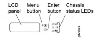
text_image
LCD panel Menu button Enter button Chassis status LEDs ALM PYS MST GD20093- On both switches in the Virtual Chassis, verify that the green ST (status) and VC MODE LEDs on the Virtual Chassis module are on steadily.
Part 8. Create a Mixed J-EX4200 and J-EX4500 Virtual Chassis

CAUTION: Do not physically connect multiple switches in a Virtual Chassis before reading these instructions.
Your switch can be part of a Virtual Chassis configuration of as many as eight J-EX4200 switches and one other J-EX4500 switch. A J-EX4500 switch must be the master.
These instructions show you how to configure two J-EX4500 switches and two J-EX4200 switches—none are current Virtual Chassis members—in a preprovisioned configuration. We highly recommend preprovisioning for a mixed Virtual Chassis.
- Ensure that both J-EX4200 switches for the mixed Virtual Chassis are initially configured. See the Dell PowerConnect J-EX4200 switch documentation at http://www.support.dell.com/manuals.
- Verify that the J-EX4200 switches and J-EX4500 switches to be connected in the mixed Virtual Chassis are all running the same version of Junos OS.
- Write down the serial numbers of the switches to be connected in the Virtual Chassis, and select a J-EX4500 switch as the master switch.
- Power on the J-EX4500 master switch first, and then power on the other J-EX4500 member switch. For a switch not previously configured, see Part 6 on page 3.
- Set both J-EX4500 switches to mixed Virtual Chassis mode, and reboot each switch: user@switch> request virtual-chassis mode mixed user@switch> request system reboot
- Power on both J-EX4200 Virtual Chassis member switches.
- Set both J-EX4200 switches to mixed Virtual Chassis mode, and reboot each switch: user@switch> request virtual-chassis mode mixed user@switch> request system reboot
- (Optional) Log back in to the master switch, enter configuration mode, and configure the virtual management Ethernet (VME) interface for out-of-band management of the Virtual Chassis:
user@switch> configure
user@switch# set interfaces vme unit 0 family inet address ip-address
Dell PowerConnect J-Series J-EX4500 Ethernet Switch Quick Start—page 5
- On the master switch, specify the preprovisioned configuration mode, and assign both J-EX4500 members (including the master) the routing-engine role:
user@switch# edit virtual-chassis user@switch# set preprovisioned user@switch# set member member-id-1 serial-number serial-number-1 role routing-engine user@switch# set member member-id-2 serial-number serial-number-2 role routing-engine
- On the master switch, continue preprovisioning by assigning both J-EX4200 members the linecard role, then commit the configuration:
user@switch# set member member-id-3 serial-number serial-number-3 role linecard user@switch# set member member-id-4 serial-number serial-number-4 role linecard user@switch# commit
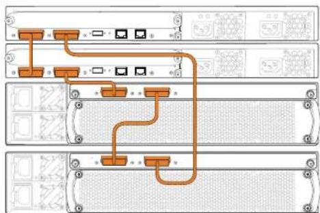
- With four Virtual Chassis cables and cable connector retainers, interconnect the four switches using the dedicated VCPs on the back of each switch.
flowchart
graph TD
    A["Port 1"] --> B["Port 2"]
    B --> C["Port 3"]
    C --> D["Port 4"]
    D --> E["Port 5"]
    E --> F["Port 6"]
    F --> G["Port 7"]
    G --> H["Port 8"]
    H --> I["Port 9"]
    I --> J["Port 10"]
    J --> K["Port 11"]
    K --> L["Port 12"]
    L --> M["Port 13"]
    M --> N["Port 14"]
    N --> O["Port 15"]
    O --> P["Port 16"]
    P --> Q["Port 17"]
    Q --> R["Port 18"]
    R --> S["Port 19"]
    S --> T["Port 20"]
- On the master switch:
- Verify that the green MST (master) LED to the right of the LCD panel is on steadily.

- Verify that the green ST (status) and VC MODE LEDs on the Virtual Chassis module are both on steadily.

text_image
VCP-0 ST VC MODE 1-
On the other J-EX4500 member switch, verify that the green MST LED is blinking and that the green ST and VC MODE LEDs are on steadily.
-
On both J-EX4200 line card members, verify that the MST LED to the right of the LCD panel is off.
Safety Warnings Summary
This is a summary of safety warnings. For a complete list of warnings, including translations, see the Dell PowerConnect J-EX4500 switch documentation at http://www.support.dell.com/manuals.

WARNING: Failure to observe these safety warnings can result in personal injury or death.
- Permit only trained and qualified personnel to install or replace switch components.
- Perform only the procedures described in this quick start and the J-EX4500 switch documentation. Only authorized service personnel must perform other services.
- Before installing the switch, read the planning instructions in the J-EX4500 switch documentation to make sure that the site meets power, environmental, and clearance requirements for the switch.
- Before connecting the switch to a power source, read the installation instructions in the J-EX4500 switch documentation.
- A J-EX4500 switch with one power supply weighs 37 lb (17 kg). With two power supplies, the switch weighs 40 lb (18 kg). Installing the switch in a rack requires one person to lift the switch and a second person to install mounting screws. To prevent injury, keep your back straight and lift with your legs, not your back.
- If the rack has stabilizing devices, install them in the rack before mounting or servicing the switch in the rack.
- Before installing or after removing an electrical component, always place it component-side up on a flat antistatic surface or in an electrostatic bag.
- Do not work on the switch or connect or disconnect cables during electrical storms.
- Before working on equipment that is connected to power lines, remove jewelry, including rings, necklaces, and watches. Metal objects heat up when connected to power and ground and can cause serious burns or become welded to the terminals.
Contacting Dell Inc.
For technical support, see http://www.support.dell.com.
Dell PowerConnect J-Series J-EX4500 Ethernet Switch Quick Start—page 6
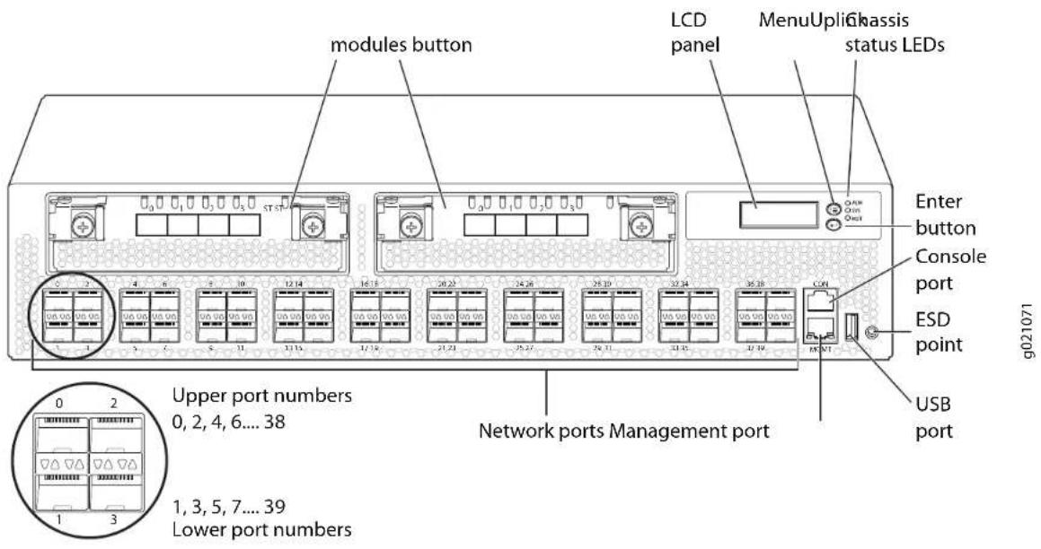
text_image
modules button LCD panel MenuUpliGhassis status LEDs Enter button Console port ESD point USB port Upper port numbers 0, 2, 4, 6... 38 Lower port numbers 1, 3, 5, 7... 39 Network ports Management port g021071Information in this document is subject to change without notice. Trademarks used in this text: Dell™, the DELL™ logo, and PowerConnect™ are trademarks of Dell Inc. Juniper Networks® and Junos® are registered trademarks of Juniper Networks, Inc. in the United States and other countries. All other trademarks, service marks, registered trademarks, or registered service marks are the property of their respective owners. Juniper Networks assumes no responsibility for any inaccuracies in this document. Juniper Networks reserves the right to change, modify, transfer, or otherwise revise this publication without notice. Products made or sold by Juniper Networks or components thereof might be covered by one or more of the following patents that are owned by or licensed to Juniper Networks: U.S. Patent Nos. 5,473,589, 5,905,725, 5,909,440, 6,192,051, 6,333,650, 6,359,479, 6,406,312, 6,429,706, 6,459,579, 6,493,347, 6,538,518, 6,538,899, 6,552,918, 6,567,902, 6,578,186, and 6,590,785. Copyright © 2011, Juniper Networks, Inc. All rights reserved. Reproduction of these materials in any manner whatsoever without the written permission of Juniper Networks is strictly forbidden. Juniper Networks Part Number: 530-038616. Revision 01, 30 April 2011.

text_image
EXHAUST VCP-5 VCP-1 EXHAUST 0027004natural_image
Technical line drawing of a rectangular electronic component with mounting brackets and dashed alignment lines (no text or symbols)text_image
Technical diagram showing four different installation or mounting configurations with labeled components and directional arrows indicating assembly or movement.
530-038616 REV 01
text_image
Technical diagram of an electronic device with labeled components and measurement annotationstext_image
Technical diagram of a mechanical device with labeled components and an orange arrow indicating direction or flow.user@switch> configure user@switch# set interfaces vme unit 0 family inet address ip-address
user@switch# edit virtual-chassis user@switch# set preprovisioned user@switch# set member 0 serial-number serial-number role routing-engine user@switch# set member 1 serial-number serial-number role routing-engine user@switch# commit
user@switch# edit virtual-chassis
user@switch# set preprovisioned
user@switch# set member member-id-1 serial-number
serial-number-1 role routing-engine
user@switch# set member member-id-2 serial-number
serial-number-2 role routing-engine
user@switch# set member member-id-3 serial-number
serial-number-3 role linecard
user@switch# set member member-id-4 serial-number
serial-number-4 role linecard
user@switch# commit
text_image
VCP-0 ST VC MODE +1text_image
EXHAUST VCP-0 VCP-1 EXHAUST 0021004natural_image
Technical line drawing of a mechanical assembly with mounting brackets and dashed alignment lines (no text or symbols)text_image
Technical diagram showing installation of a wall-mounted electrical socket with mounting holes and wiring connections
530-038616 REV 01
text_image
Technical diagram of an electronic device with labeled components and measurement indicatorstext_image
Technical diagram of a mechanical device with labeled components and an orange arrow indicating direction or flow.user@switch# edit virtual-chassis
user@switch# set preprovisioned
user@switch# set member 0 serial-number serial-number role
routing-engine
user@switch# set member 1 serial-number serial-number role
routing-engine
user@switch# commit
user@switch# set interfaces vme unit 0 family inet address ip-address
user@switch# edit virtual-chassis
user@switch# set preprovisioned
user@switch# set member member-id-1 serial-number
serial-number-1 role routing-engine
user@switch# set member member-id-2 serial-number
serial-number-2 role routing-engine
user@switch# set member member-id-3 serial-number
serial-number-3 role linecard
user@switch# set member member-id-4 serial-number
serial-number-4 role linecard
user@switch# commit
text_image
VCP-0 ST VC MODE +1natural_image
Technical line drawing of a rectangular electronic component with vertical supports and dashed lines indicating hidden edges (no text or symbols)text_image
Technical diagram showing electrical connector assembly with labeled components and directional arrows indicating connection points.
530-038616 REV 01
Commutateur Ethernet Dell PowerConnect J-Series J-EX4500 - Guide de mise en route (page 2)
text_image
Technical diagram of a computer control panel with labeled components and measurement annotationstext_image
VCP-0 ST VC MODE 1text_image
Technical diagram showing a mechanical device with labeled components and an orange arrow indicating direction or flow.user@switch# edit virtual-chassis user@switch# set preprovisioned user@switch# set member member-id-1 serial-number serial-number-1 role routing-engine user@switch# set member member-id-2 serial-number serial-number-2 role routing-engine
text_image
VCP-0 ST VC MODE +1text_image
EXHAUST VCP-0 VCP-1 EXHAUST QD21304natural_image
Technical line drawing of a rectangular structural component with dashed alignment lines and bolted joints (no text or symbols)text_image
Technical diagram showing four different installation or assembly steps with labeled components and directional arrows
530-038616 REV 01
text_image
Technical diagram of an electronic device with labeled components and measurement annotationstext_image
Technical diagram showing a mechanical device with labeled components and an orange arrow indicating direction or force.user@switch# edit virtual-chassis user@switch# set preprovisioned user@switch# set member member-id-1 serial-number serial-number-1 role routing-engine user@switch# set member member-id-2 serial-number serial-number-2 role routing-engine
user@switch# set member member-id-3 serial-number serial-number-3 role linecard user@switch# set member member-id-4 serial-number serial-number-4 role linecard user@switch# commit
text_image
VCP-0 ST VC MODE +1text_image
EXHAUST VOP-0 VOP-1 EXHAUST Q221064natural_image
Technical line drawing of a rectangular electronic component with mounting holes and dashed lines indicating hidden edges (no text or symbols)text_image
Technical diagram showing four different installation or mounting methods with labeled components and arrows indicating assembly steps.
530-038616 REV 01
Panduan Ringkas Dell PowerConnect J-Series J-EX4500 Ethernet Switch—halaman 2
text_image
Technical diagram of an electronic device with labeled components and connection linestext_image
VCP-0 ST VC MODE 1- Perhatikan LED alarm kuning tua di sebelah kanan panel LCD.
text_image
Technical diagram showing a mechanical device with labeled components and an orange arrow indicating direction or force.text_image
VCP-0 ST VC MODE 1user@switch# set interfaces vme unit 0 family inet address ip-address
Panduan Ringkas Dell PowerConnect J-Series J-EX4500 Ethernet Switch—halaman 5
- Pada switch master, tetapkan mode konfigurasi preprovisioned, lalu tetapkan peran routing-engine ke kedua anggota J-EX4500 (termasuk master):
user@switch# edit virtual-chassis user@switch# set preprovisioned user@switch# set member member-id-1 serial-number serial-number-1 role routing-engine user@switch# set member member-id-2 serial-number serial-number-2 role routing-engine
user@switch# set member member-id-3 serial-number serial-number-3 role linecard user@switch# set member member-id-4 serial-number serial-number-4 role linecard user@switch# commit
text_image
VCP-0 ST VC MODE 1text_image
EXHAUST VCP-0 VCP-1 EXHAUST Q021064text_image
Technical diagram showing electrical mounting bracket installation with labeled components and assembly steps
530-038616 REV 01
text_image
Technical diagram of an electronic device with labeled components and measurement annotationsnatural_image
Technical line drawing of a mechanical device with no visible text or symbolsuser@switch# set interfaces vme unit 0 family inet address
ip-address
user@switch# edit virtual-chassis user@switch# set preprovisioned user@switch# set member member-id-1 serial-number serial-number-1 role routing-engine user@switch# set member member-id-2 serial-number serial-number-2 role routing-engine
user@switch# set member member-id-3 serial-number serial-number-3 role linecard user@switch# set member member-id-4 serial-number serial-number-4 role linecard user@switch# commit
text_image
VCP-0 ST VC MODE +1natural_image
Technical line drawing of a rectangular electronic component with mounting brackets and dashed alignment lines (no text or symbols)text_image
Technical diagram showing three steps of a mechanical assembly or mounting process with labeled components and directional arrows.
530-038616 REV 01
text_image
Technical diagram of an electronic device with labeled components and annotations in Chinesetext_image
VCP-0 ST VC MODE 1text_image
Technical diagram showing a mechanical device with labeled components and an orange arrow indicating direction or force.user@switch# set interfaces vme unit 0 family inet address ip-address
user@switch# set member 0 serial-number serial-number role routing-engine
user&switch# set member 1 serial-number serial-number role routing-engine
user@switch# commit
user@switch# set member member-id-1 serial-number
serial-number-1 role routing-engine
user@switch# set member member-id-2 serial-number
serial-number-2 role routing-engine
user@switch# set member member-id-3 serial-number
serial-number-3 role linecard
user@switch# set member member-id-4 serial-number
serial-number-4 role linecard
user@switch# commit
text_image
VCP-0 ST VC MODE +1text_image
EXHAUST VCP-0 VCP-1 EXHAUST Φ21064natural_image
Technical line drawing of a rectangular electronic device with mounting brackets and wiring (no text or symbols)text_image
Technical diagram of an electronic device with labeled components and connection pointstext_image
VCP-0 ST VC MODE 1text_image
Technical diagram showing a mechanical device with labeled components and an orange arrow indicating direction or force.user@switch# edit virtual-chassis user@switch# set preprovisioned user@switch# set member member-id-1 serial-number serial-number-1 role routing-engine user@switch# set member member-id-2 serial-number serial-number-2 role routing-engine
user@switch# set member member-id-3 serial-number serial-number-3 role linecard user@switch# set member member-id-4 serial-number serial-number-4 role linecard user@switch# commit
text_image
VCP-0 ST VC MODE #1text_image
EXHAUST VCP-0 VCP-1 EXHAUST DC11964natural_image
Technical line drawing of a mechanical assembly with mounting brackets and dashed alignment lines (no text or symbols)text_image
Technical diagram showing installation steps of a wall-mounted switch or socket, with labeled components and directional arrows.
530-038616 REV 01
text_image
Technical diagram of a device with labeled ports and control panel, showing internal components and measurement annotations.text_image
VCP-0 ST VC MODE 1text_image
Technical diagram of a mechanical device with labeled components and directional arrow indicating flow or movementuser@switch# set interfaces vme unit 0 family inet address ip-address
user@switch# edit virtual-chassis
user@switch# set preprovisioned
user@switch# set member 0 serial-number serial-number role routing-engine
user@switch# set member 1 serial-number serial-number role routing-engine
user@switch# commit
user@switch# set interfaces vme unit 0 family inet address ip-address
user@switch# edit virtual-chassis user@switch# set preprovisioned user@switch# set member member-id-1 serial-number serial-number-1 role routing-engine user@switch# set member member-id-2 serial-number serial-number-2 role routing-engine
text_image
VCP-0 ST VC MODE +1text_image
EXHAUST VCP-0 VCP-1 EXHAUST Φ21064natural_image
Technical line drawing of a rectangular electronic component mounted on vertical rails, with no visible text or symbols.text_image
Technical diagram of an electronic device with labeled components and internal structure annotationstext_image
Technical diagram showing a mechanical device with labeled components and an orange arrow indicating direction or force.text_image
VCP-0 ST VC MODE 1text_image
VCP-0 ST VC MODE +1natural_image
Technical line drawing of a mechanical assembly with mounting brackets and dashed alignment lines (no text or symbols)text_image
EXHAUST VCP-0 VCP-1 EXHAUST 0021064on' 90° 75' 12:30' 12:30' 12:30' 12:30' 12:30' 12:30' 12:30' 12:30' 12:30' 12:30' 12:30' 12:30' 12:30' 12:30' 12:30'
(1) OFF (2) OK (3) OK (4) OK (5) OK (6) OK (7) OK (8) OK (9) OK (10) OK (11) OK (12) OK (13) OK (14) OK (15) OK (16) OK (17) OK (18) OK (19) OK (20) OK (21) OK (22) OK (23) OK (24) OK (25) OK (26) OK (27) OK (28) OK (29) OK (30) OK (31) OK (32) OK (33) OK (34) OK (35) OK (36) OK (37) OK (38) OK (39) OK (40) OK (41) OK (42) OK (43) OK (44) OK (45) OK (46) OK (47) OK (48) OK (49) OK (50) OK (51) OK (52) OK (53) OK (54) OK (55) OK (56) OK (57) OK (58) OK (59) OK (60) OK (61) OK (62) OK (63) OK (64) OK (65) OK (66) OK (67) OK (68) OK (69) OK (70) OK (71) OK (72) OK (73) OK (74) OK (75) OK (76) OK (77) OK (78) OK (79) OK (80) OK (81) OK (82) OK (83) OK (84) OK (85) OK (86) OK (87) OK (88) OK (89) OK (90) OK (91) OK (92) OK (93) OK (94) OK (95) OK (96) OK (97) OK (98) OK (99) OK (100).
text_image
Technical diagram of an electronic device with labeled components and internal structure annotations8.
text_image
VCP-0 ST VC MODE 1.LCD-הַרְעָהִי, אַרְעָהִי, אַרְעָהִי LED-הַרְעָהִי, 18
. Opening LED is given (70x) Enter-1 (70x) Menu is given, LCD-75 is given .5

text_image
LCD Menu Enter LED 020093text_image
VCP-0 ST VC MODE 1J-EX4500 Virtual Chassis-J-EX4200 877
user@switch# set interfaces vme unit 0 family inet address
ip-address
J-EX4500 J-EX4500 Virtual Chassis:7
text_image
Technical diagram showing a mechanical device with labeled components and an orange arrow indicating flow direction.الإستعمال: 3
user@switch|set interfaces vme unit 0 family inet address
ip-address
user@switch# set member 0 serial-number serial-number role
routing-engine
user@switch# set member 1 serial-number serial-number role
routing-engine
user@switch# commit
text_image
LCD Menu Enter LED ALM SYS MST g020093text_image
VCP-0 ST VC MODEuser@switch# set member member-id-1 serial-number
serial-number-I role routing-engine
user@switch# set member member-id-2 serial-number
serial-number-2 role routing-engine
linecard J-EX4200, 10
user@switch# set member member-id-3 serial-number serial-number-3 role linecard
user@switch| set member member-id-4 serial-number
serial-number-4 role linecard
user@switch# commit
Juniper Networks, Inc. man who don't know that he is on Junos® Juniper Networks® Dell Inc man who don't know on PowerConnect™-DELL™, Dell™: and his son of the company's name in the case of the company's name. Juniper Networks man who don't know on PowerConnect™-DELL™, Dell™: and his son of the company's name in the case of the company's name. Juniper Networks man who don't know on PowerConnect™-DELL™, Dell™: and his son of the company's name in the case of the company's name. Juniper Networks man who don't know on PowerConnect™-DELL™, Dell™: and his son of the company's name, and his son of the company's name. Juniper Networks man who don't know on PowerConnect™-DELL™, Dell™: and his son of the company's name, and his son of the company's name. Juniper Networks man who don't know on PowerConnect™-DELL™, Dell™: and his son of the company's name, and his son of the company's name. Juniper Networks man who don't know on PowerConnect™-DELL™, Bell™: and his son of the company's name, and his son of the company's name, and his son of the company's name. Juniper Networks man who don't know on PowerConnect™-DELL™, Bell™: and his son of the company's name, and his son of the company's name, and his son of the company's name. Juniper Networks man who don't know on PowerConnect™-DELL™, Bell™: and his son of the company's name, and his son of the Company's name, and his son of the Company's name, and his son of the Company's name. Juniper Networks man who don't know on PowerConnect™-DELL™, Bell™: and his son of the Company's name, and his son of the Company's name, and his son of the Company's name, and his son of the Company's name. Juniper Networks man who don't know on PowerConnect™-DELL™, Bell™: and his son of the Company's name, and his son of the Company's name, and his son of the Company's name, and his son of the Company's name. Juniper Networks man who don't know on PowerConnect™-DALE™, Bell™: and his son of the Company's name, and his son of the Company's name, and his son of the Company's name, and his son of the Company's name, and his son of the Company's name. Juniper Networks man who don't know on PowerConnect™-DALE™, Bell™: and his son of the Company's name, and his son of the Company's name, and his son of the Company's name, and his son of the Company's name. Juniper Networks man who don't know on PowerConnect™-DALE™, Bell™: and his son of the Company's name, and his son of the Company's name, and his son of the Company's name, and his son of the Company's name. Juniper Networks man who don't show on PowerConnect™-DALE™, Bell™: and his son of the Company's name, and his son of the Company's name, and his son of the Company's name, and his son of the Company's name. Juniper Networks man who don't show on PowerConnect™-DALE™, Bell™: and his son of the Company's name, and his son of the Company's name, and his son of the Company's name, and his son of The Company's name. Juniper Networks man who don't show on PowerConnect™-DALE™, Bell™: and his son of the Company's name, and his son of the Company's name, and his son of the Company's name, and his son of the Company's name. Juniper Networks man who don't show on PowerConnect™-DALE™, Bell™: and his son of the Company's name, and his son of the Company's name, and its son of the Company's name. Juniper Networks man who don't show on PowerConnect™-DALE™, Bell™: and his son of the Company's name, and his son of the Company's name, and his son of the Company's name. Juniper Networks man who don't show on PowerConnect™-DALE™, Bell™: and his son of the Company's name, and his son of the Company's name, and his son of the Company's name. Juniper Networks man who don't show on PowerConnect™-DALE™, Bell™: and his son of the Company's name, and his son of the Company's name, and his son of the Company's Name. Juniper Networks man who don't show on PowerConnect™-DALE™, Bell™: and his son of the Company's name, and his son of the Company's name, and his son of the Company's Name. Juniper Networks man who don't show on PowerConnect™-DALE™, Bell™: and his son of the Company's name, and his son of the Company's Name. Juniper Networks man who don't show on PowerConnect™-DALE™, Bell™: and his son of the Company's Name, and his son of the Company's Name. Juniper Networks man who don't show on PowerConnect™-DALE™, Bell™: and his son of the Company's Name, and his son of the Company's Name. Juniper Networks man who don't show on PowerConnect™-DALE™, Bell™: and his son of the Company's Name, and his son of the Company's Name. Juniper Networks man who don't show on PowerConnect™-DARTEM-DALETM-DALETM-DALETM-DALETM-DALETM-DALETM-DALETM-DALETM-DALETM-DALETM-DALETM-DALETM-DALETM-DALETM-DALETM-DALETM-DALETM-DALETM-DALETM-DALETM-DALETM-DALETM-DALETM-DALETM-DALETM-DALEMTDARTEM-DALETM-DALETM-DALETM-DALETM-DALETM-DALETM-DALETM-DALETM-DALETM-DALETM-DALETM-DALETM-DALETM-DALETM-DALETM-DALETM-DALETM-DALETM-DALETM-DALETM-DARTEM-DALETM-DALETM-DALETM-DALETM-DALETM-DALETM-DALETM-DALETM-DARTEM-DARTEM-DARTEM-DARTEM-DARTEM-DARTEM-DARTEM-DARTEM-DARTEM-DARTEM-DARTEM-DARTEM-DARTEM-DARTEM-DARTEM-DARTEM-DARTEM-DARTEM-DARTEM-DARTEM-DARTEM-DARTEM-DARTEM-DARTEM-DARTEM-DARTEMTDARTEM-DARTEM-DARTEM-DARTEM-DARTEM-DARTEM-DARTEM-DARTEM-DARTEM-DARTEM-DARTEM-DARTEM-DARTEM-DARTEM-DARTEM-DARTEM-DARTEM-DARTEM-DARTEM-DARTEM-DARTEM-DARTEM-DARTEM-DARTEM-DARTEM