PowerConnect 3048 - Router DELL - Free user manual and instructions
Find the device manual for free PowerConnect 3048 DELL in PDF.
| Product Type | 48-port managed network switch |
| Brand | Dell |
| Model | PowerConnect 3048 |
| Category | Router / Switch |
| Dimensions (approx.) | 44.5 x 30.5 x 4.4 cm (1U) |
| Weight (approx.) | 5.4 kg |
| Power Supply | 100-240 V AC, 50-60 Hz, power cord |
| Network Ports | 48 RJ-45 10/100/1000 ports, 2 GBIC slots |
| Console Port | 1 RS-232 DB-9 male serial port (DTE) |
| Management | Web interface, console (VT100 terminal emulation), command line interface |
| Key Features | Layer 2 switching, VLAN, QoS, link aggregation, password security |
| Password Protection | Active by default (user root, password switch), changeable |
| IP Address | Static assignment via console or DHCP (depending on configuration) |
| Installation | Desktop (rubber feet) or 19-inch rack (kit provided) |
| Ventilation | Free space of at least 5.1 cm on sides, 12.7 cm at rear |
| Maintenance and Cleaning | Clean exterior with a soft, dry cloth; do not use liquids |
| Safety | Complies with CE standards (EN 55022 Class A, EN 55024, EN 60950); precautions against electrostatic discharge |
| Spare Parts / Repairability | Contact Dell technical support for any replacement or repair |
| Package Contents | Switch, power cord, console cable, rubber feet, rack mount kit, CD with documentation |
| Warranty | Standard manufacturer warranty, coverage varies by region |
| General Information | 176-page manual available in multiple languages; online support at support.euro.dell.com |
Frequently Asked Questions - PowerConnect 3048 DELL
User questions about PowerConnect 3048 DELL
0 question about this device. Answer the ones you know or ask your own.
Ask a new question about this device
Download the instructions for your Router in PDF format for free! Find your manual PowerConnect 3048 - DELL and take your electronic device back in hand. On this page are published all the documents necessary for the use of your device. PowerConnect 3048 by DELL.
USER MANUAL PowerConnect 3048 DELL
Systeminformationshandbuch
Notes, Notices, and Cautions

NOTE: A NOTE indicates important information that helps you make better use of your system.

NOTICE: A NOTICE indicates either potential damage to hardware or loss of data and tells you how to avoid the problem.

CAUTION: A CAUTION indicates a potential for property damage, personal injury, or death.
Information in this document is subject to change without notice. © 2002 Dell Computer Corporation. All rights reserved.
Reproduction in any manner whatsoever without the written permission of Dell Computer Corporation is strictly forbidden.
Trademarks used in this text: Dell, the DELL logo, and PowerConnect are trademarks of Dell Computer Corporation; Microsoft and Windows are registered trademarks of Microsoft Corporation; EMC is the registered trademark of EMC corporation.
Other trademarks and trade names may be used in this document to refer to either the entities claiming the marks and names or their products. Dell Computer Corporation disclaims any proprietary interest in trademarks and trade names other than its own.
October 2002 P/N 3X685 Rev. A00
Contents
Caution: Safety Instructions 5
General 5
Rack Mounting of Systems 6
Modems, Telecommunications, or Local Area Network Options 8
When Working Inside Your System 8
Protecting Against Electrostatic Discharge 8
About This Guide 9
Finding Information and Assistance 10
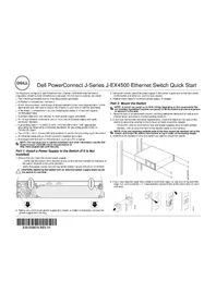
Getting Started/Setup 10
Package Contents 10
Before You Connect to the Network: Mounting Kit Instructions ..... 11
Connecting the Console Port. 12
Password Protection 13
IP Address Assignment 14
Connecting Devices to the Switch 15
Regulatory Information 15
CE Notice (European Union) 17
EN 55022 Compliance (Czech Republic Only) ..... 18
Polish Center for Testing and Certification Notice ..... 18
Caution: Safety Instructions
Use the following safety guidelines to ensure your own personal safety and to help protect your system from potential damage.
General
- Observe and follow service markings. Do not service any product except as explained in your system documentation. Opening or removing covers that are marked with the triangular symbol with a lightning bolt may expose you to electrical shock. Components inside these compartments should be serviced only by a trained service technician.
-
If any of the following conditions occur, unplug the product from the electrical outlet and replace the part or contact your trained service provider:
-
The power cable, extension cable, or plug is damaged.
- An object has fallen into the product.
– The product has been exposed to water.
– The product has been dropped or damaged. -
The product does not operate correctly when you follow the operating instructions.
-
Keep your system away from radiators and heat sources. Also, do not block cooling vents.
- Do not spill food or liquids on your system components, and never operate the product in a wet environment. If the system gets wet, see the appropriate section in your troubleshooting guide or contact your trained service provider.
- Do not push any objects into the openings of your system. Doing so can cause fire or electric shock by shorting out interior components.
- Use the product only with approved equipment.
- Allow the product to cool before removing covers or touching internal components.
- Operate the product only from the type of external power source indicated on the electrical ratings label. If you are not sure of the type of power source required, consult your service provider or local power company.
Caution: Safety Instructions (continued)
- Use only approved power cable(s). If you have not been provided with a power cable for your system or for any AC-powered option intended for your system, purchase a power cable that is approved for use in your country. The power cable must be rated for the product and for the voltage and current marked on the product's electrical ratings label. The voltage and current rating of the cable should be greater than the ratings marked on the product.
- To help prevent electric shock, plug the system and peripheral power cables into properly grounded electrical outlets. These cables are equipped with three-prong plugs to help ensure proper grounding. Do not use adapter plugs or remove the grounding prong from a cable. If you must use an extension cable, use a 3-wire cable with properly grounded plugs.
- Observe extension cable and power strip ratings. Make sure that the total ampere rating of all products plugged into the extension cable or power strip does not exceed 80 percent of the ampere ratings limit for the extension cable or power strip.
- To help protect your system from sudden, transient increases and decreases in electrical power, use a surge suppressor, line conditioner, or uninterruptible power supply (UPS).
- Position system cables and power cables carefully; route cables so that they cannot be stepped on or tripped over. Be sure that nothing rests on any cables.
- Do not modify power cables or plugs. Consult a licensed electrician or your power company for site modifications. Always follow your local/national wiring rules.
- When connecting or disconnecting power to hot-pluggable power supplies, if offered with your system, observe the following guidelines:
- Install the power supply before connecting the power cable to the power supply.
- Unplug the power cable before removing the power supply.
- If the system has multiple sources of power, disconnect power from the system by unplugging all power cables from the power supplies.
- Move products with care; ensure that all casters and/or stabilizers are firmly connected to the system. Avoid sudden stops and uneven surfaces.
Rack Mounting of Systems
Observe the following precautions for rack stability and safety. Also refer to the rack installation documentation accompanying the system and the rack for specific caution statements and procedures.
Caution: Safety Instructions (continued)
Systems are considered to be components in a rack. Thus, "component" refers to any system as well as to various peripherals or supporting hardware.

CAUTION: Installing systems in a rack without the front and side stabilizers installed could cause the rack to tip over, potentially resulting in bodily injury under certain circumstances. Therefore, always install the stabilizers before installing components in the rack.
After installing system/components in a rack, never pull more than one component out of the rack on its slide assemblies at one time. The weight of more than one extended component could cause the rack to tip over and may result in serious injury.

NOTE: Your system is safety-certified as a free-standing unit and as a component for use in a Dell rack cabinet using the customer rack kit. The installation of your system and rack kit in any other rack cabinet has not been approved by any safety agencies. It is your responsibility to have the final combination of system and rack kit in a rack cabinet evaluated for suitability by a certified safety agency. Dell disclaims all liability and warranties in connection with such combinations.
- System rack kits are intended to be installed in a rack by trained service technicians. If you install the kit in any other rack, be sure that the rack meets the specifications of a Dell rack.

CAUTION: Do not move racks by yourself. Due to the height and weight of the rack, a minimum of two people should accomplish this task.
- Before working on the rack, make sure that the stabilizers are secured to the rack, extended to the floor, and that the full weight of the rack rests on the floor. Install front and side stabilizers on a single rack or front stabilizers for joined multiple racks before working on the rack.
- Always load the rack from the bottom up, and load the heaviest item in the rack first.
- Make sure that the rack is level and stable before extending a component from the rack.
- Use caution when pressing the component rail release latches and sliding a component into or out of a rack; the slide rails can pinch your fingers.
- After a component is inserted into the rack, carefully extend the rail into a locking position, and then slide the component into the rack.
- Do not overload the AC supply branch circuit that provides power to the rack. The total rack load should not exceed 80 percent of the branch circuit rating.
- Ensure that proper airflow is provided to components in the rack.
Caution: Safety Instructions (continued)
- Do not step on or stand on any component when servicing other components in a rack.
CAUTION: A qualified electrician must perform all connections to DC power and to safety grounds. All electrical wiring must comply with applicable local or national codes and practices.
CAUTION: Never defeat the ground conductor or operate the equipment in the absence of a suitably installed ground conductor. Contact the appropriate electrical inspection authority or an electrician if you are uncertain that suitable grounding is available.
CAUTION: The system chassis must be positively grounded to the rack cabinet frame. Do not attempt to connect power to the system until grounding cables are connected. Completed power and safety ground wiring must be inspected by a qualified electrical inspector. An energy hazard will exist if the safety ground cable is omitted or disconnected.
Modems, Telecommunications, or Local Area Network Options
- Do not connect or use a modem during a lightning storm. There may be a risk of electrical shock from lightning.
- Never connect or use a modem in a wet environment.
- Do not plug a modem or telephone cable into the network interface controller (NIC) receptacle.
- Disconnect the modem cable before opening a product enclosure, touching or installing internal components, or touching an uninsulated modem cable or jack.
When Working Inside Your System
Protecting Against Electrostatic Discharge
NOTICE: Only a certified service technician should perform repairs on your system. Damage due to servicing that is not authorized by Dell is not covered by your warranty.
Static electricity can harm delicate components inside your system. To prevent static damage, discharge static electricity from your body before you touch any of the electronic components, such as the microprocessor. You can do so by periodically touching an unpainted metal surface on the chassis.

Caution: Safety Instructions (continued)
You can also take the following steps to prevent damage from electrostatic discharge (ESD):
- When unpacking a static-sensitive component from its shipping carton, do not remove the component from the antistatic packing material until you are ready to install the component in your system. Just before unwrapping the antistatic packaging, be sure to discharge static electricity from your body.
- When transporting a sensitive component, first place it in an antistatic container or packaging.
- Handle all sensitive components in a static-safe area. If possible, use antistatic floor pads and workbench pads and an antistatic grounding strap.

NOTE: Your system may also include circuit cards or other components that contain batteries. These batteries must also be disposed of in a battery deposit site. For information about such batteries, refer to the documentation for the specific card or component.
About This Guide
This document contains getting started/setup, safety, regulatory, and warranty information about your Dell ^™ PowerConnect ^™ network switch.
To obtain the latest versions of the documents on your hard drive, go to the Dell Support website at support.dell.com.
Finding Information and Assistance
Resource Contents Using the Resource
| Dell Support website• Technical support and information• Downloads for your system• Order or delivery status• Hints and tips, technology papers, service information | Go tosupport.dell.comand complete the one-time registration.• Get help with general usage, installation, and troubleshooting questions.• Obtain answers to technical service and support questions.• Get the latest versions of the drivers for your system.• Access documentation about your system and devices.• Join online discussions with other Dell customers and Dell technical professionals.• Explore a list of online links to Dell's primary vendors. | |
| Premier Support.Dell.com | Dell Premier Support website• Service call status• Top technical issues by product• Frequently asked questions by product number• Customized service tags• System configuration detail | Go topremiersupport.dell.com:The Dell Premier Support website is customized for corporate, government, and education customers.This site may not be available in all regions. |
Getting Started/Setup
Package Contents
Before you begin installing the switch, confirm that your package contains the following items:
- Switch
- AC power cable
- Null modem cable
-
Self-adhesive rubber pads for desktop installation
-
Rackmount kit for rack installation
- Dell PowerConnect CD
Before You Connect to the Network: Mounting Kit Instructions

NOTICE: Do not connect the switch to the network until you have established the correct Internet Protocol (IP) settings.
Before you connect to the network, you must install the switch on a flat surface or in a rack, set up a terminal emulation program, and plug in the power cable. Then you will set up a password and IP address.
The switch is supplied with rubber feet for stationing it on a flat surface and mounting brackets and screws for mounting it in a rack.
Installing on a Flat Surface
The switch can be installed on any appropriate level surface that can safely support the weight of the hubs and their attached cables. There must be adequate space around the switch for ventilation and access to cable connectors.
To install the switch on a flat surface:
1 Set the switch on the flat surface and check for proper ventilation.
Allow at least 5.1 cm (2 inches) on each side for proper ventilation and 12.7 cm (5 inches) at the back for power cable clearance.
2 Attach rubber feet on each marked location on the bottom of the chassis.
The rubber feet are optional but recommended to keep the unit from slipping.
Installing in a Rack
The switch can be installed in most standard 48.3-cm (19-inch) racks.
To install the switch in a rack:
1 Use the supplied screws to attach a mounting bracket to each side of the switch.
2 Position the switch in the rack and align the holes in the mounting bracket with the holes in the rack.

NOTE: For racks that are not prethreaded, cage nuts are provided.
3 Insert and tighten two screws appropriate for your rack through each of the mounting brackets.
Connecting the Console Port
The switch provides an RS-232 serial port that enables a connection to a desktop system or terminal for monitoring and configuring the switch. This port is a male DB-9 connector, implemented as a data terminal equipment (DTE) connection.
To use the console port, you need the following equipment:
- A terminal or TTY-compatible terminal, or a desktop or portable system with a serial port and the capability to emulate a terminal
- A null modem or crossover RS-232 cable with a female DB-9 connector for the console port on the switch
To connect a terminal to the console port:
1 Connect the female connector of the RS-232 cable directly to the console port on the switch, and tighten the captive retaining screws.
2 Connect the other end of the cable to a terminal or the serial connector of a desktop system running terminal emulation software.
Ensure the terminal emulation software is set as follows:
aSelect the appropriate serial port (serial port 1 or serial port 2).
bSet the data rate to 9600 baud.
cSet the data format to 8 data bits, 1 stop bit, and no parity.
d Set flow control to none.
e Under Properties, select VT100 for Emulation mode.
f Select Terminal keys for Function, Arrow, and Ctrl keys. Ensure that the setting is for Terminal keys (not Windows keys).

NOTICE: When using HyperTerminal with Microsoft® Windows® 2000, ensure that you have Windows 2000 Service Pack 2 or later installed. With Windows 2000 Service Pack 2, the arrow keys function properly in HyperTerminal's VT100 emulation. Go to www.microsoft.com for information on Windows 2000 service packs.
3 Once you have set up the terminal correctly, plug the power cable into the power receptacle on the back of the switch.
The boot sequence appears in the terminal.
Password Protection
From the initial welcome screen, you must enter a password to proceed, if password protection is enabled. If password protection is disabled, the Main Menu is displayed and you immediately have access to the switch management interface. By default, password protection is disabled. If enabled, the default password is switch and the default username is root.

text_image
PowerConnect 5012 System Manager/Security Admin Web Access is: Enabled Password Protection is: Disabled New Password: Verify Password: HitTo prevent unauthorized access to the switch, turn on password protection:
1 Select System Manager and press
Use the
2 Select Security Admin.
3 Type your password and press

NOTE: The first time you set up Password Protection, you must do it from the console screen. Once the switch is set up, it can be managed through the web interface. See Section 3, "Web Interface," for more information.
4 Type your password again to confirm it and press
5 Press

NOTE: If you enable password protection without setting your own password, the default password is switch.
IP Address Assignment

text_image
PowerConnect 5012 System Manager/IP Settings IP Address: 192.168.67.3 Network Mask: 255.255.240.0 Gateway Address: 192.168.69.250 Enter this switch's IP addressBefore you can assign an IP address to the switch, you must obtain the following information from your network administrator:
• IP address for the switch
- Default gateway for the network
• Network mask for this network
To assign an IP address to the switch:
1 From the Main Menu, select System Manager and press
2 Select IP Settings.
3 In the first field, type the correct IP address for the system.
4 Enter the IP address of the default gateway for the network to which the switch belongs.
5 Enter the network mask for this network.
6 Press
7 After you make IP changes, restart the system.
8 Press
9 Select System Manager and then select Reset to restart the switch.
Confirm the reset.

NOTICE: You must restart the system from the System Manager/Reset page for the changes to take effect.
Connecting Devices to the Switch
At this point, you are ready to use appropriate network cabling to connect devices to the switch's RJ-45 connectors.
To connect a device to a CBIC port:
1 Use your cabling requirements to select an appropriate GBIC module type.
2 Insert the GBIC module (sold separately) into the GBIC slot.
3 Use the appropriate network cabling to connect a device to the connectors on the GBIC module.
Regulatory Information
Electromagnetic Interference (EMI) is any signal or emission, radiated in free space or conducted along power or signal leads, that endangers the functioning of a radio navigation or other safety service or seriously degrades, obstructs, or repeatedly interrupts a licensed radio communications service. Radio communications services include but are not limited to AM/FM commercial broadcast, television, cellular services, radar, air-traffic control, pager, and Personal Communication Services (PCS). These licensed services, along with unintentional radiators such as digital devices, including computer systems, contribute to the electromagnetic environment.
Electromagnetic Compatibility (EMC) is the ability of items of electronic equipment to function properly together in the electronic environment. While this computer system has been designed and determined to be compliant with regulatory agency limits for EMI, there is no guarantee that interference will not occur in a particular installation. If this equipment does cause interference with radio communications services, which can be determined by turning the equipment off and on, you are encouraged to try to correct the interference by one or more of the following measures:
- Reorient the receiving antenna.
- Relocate the computer with respect to the receiver.
- Move the computer away from the receiver.
- Plug the computer into a different outlet so that the computer and the receiver are on different branch circuits.
If necessary, consult a Dell Technical Support representative or an experienced radio/television technician for additional suggestions.
Dell computer systems are designed, tested, and classified for their intended electromagnetic environment. These electromagnetic environment classifications generally refer to the following harmonized definitions:
• Class A is typically for business or industrial environments.
• Class B is typically for residential environments.
Information Technology Equipment (ITE), including peripherals, expansion cards, printers, input/output (I/O) devices, monitors, and so on, that are integrated into or connected to the system should match the electromagnetic environment classification of the computer system.
A Notice About Shielded Signal Cables: Use only shielded cables for connecting peripherals to any Dell device to reduce the possibility of interference with radio communications services. Using shielded cables ensures that you maintain the appropriate EMC classification for the intended environment. For parallel printers, a cable is available from Dell. If you prefer, you can order a cable from Dell on the World Wide Web at accessories.us.dell.com/sna/category.asp?category_id=4117.
Most Dell computer systems are classified for Class B environments. However, the inclusion of certain options can change the rating of some configurations to Class A. To determine the electromagnetic classification for your system or device, refer to the following sections specific for each regulatory agency. Each section provides country-specific EMC/EMI or product safety information.
CE Notice (European Union)
Marking by the symbol indicates compliance of this Dell computer to the EMC Directive and the Low Voltage Directive of the European Union. Such marking is indicative that this Dell system meets the following technical standards:
- EN 55022 — "Information Technology Equipment — Radio Disturbance Characteristics — Limits and Methods of Measurement."
- EN 55024 — "Information Technology Equipment - Immunity Characteristics - Limits and Methods of Measurement."
- EN 61000-3-2 — "Electromagnetic Compatibility (EMC) - Part 3: Limits - Section 2: Limits for Harmonic Current Emissions (Equipment Input Current Up to and Including 16 A Per Phase)."
- EN 61000-3-3 — "Electromagnetic Compatibility (EMC) - Part 3: Limits - Section 3: Limitation of Voltage Fluctuations and Flicker in Low-Voltage Supply Systems for Equipment With Rated Current Up to and Including 16 A."
• EN 60950 — "Safety of Information Technology Equipment."
NOTE: EN 55022 emissions requirements provide for two classifications:
• Class A is for typical commercial areas.
• Class B is for typical domestic areas.
RF INTERFERENCE WARNING: This is a Class A product. In a domestic environment this product may cause radio frequency (RF) interference, in which case the user may be required to take adequate measures.
A "Declaration of Conformity" in accordance with the preceding directives and standards has been made and is on file at Dell Computer Corporation Products Europe BV, Limerick, Ireland.
EN 55022 Compliance (Czech Republic Only)
This device belongs to Class B devices as described in EN 55022, unless it is specifically stated that it is a Class A device on the specification label. The following applies to devices in Class A of EN 55022 (radius of protection up to 30 meters). The user of the device is obliged to take all steps necessary to remove sources of interference to telecommunication or other devices.
Polish Center for Testing and Certification Notice
The equipment should draw power from a socket with an attached protection circuit (a 3-prong socket). All equipment that works together (computer, monitor, printer, and so on) should have the same power supply source.
The phasing conductor of the room's electrical installation should have a reserve short-circuit protection device in the form of a fuse with a nominal value no larger than 16 amperes (A).
To completely switch off the equipment, the power supply cable must be removed from the power supply socket, which should be located near the equipment and easily accessible.
A protection mark "B" confirms that the equipment is in compliance with the protection usage requirements of standards PN-93/T-42107 and PN-EN 55022: 1996.
text_image
PowerConnect 5012 System Manager/Security Admin Web Access is: Enabled Password Protection is: Disabled New Password: Verify Password: Hittext_image
PowerConnect 5012 System Manager/IP Settings IP Address: 192.168.67.3 Network Mask: 255.255.240.0 Gateway Address: 192.168.69.250 Enter this switch's IP addressThis device belongs to Class B devices as described in EN 55022, unless it is specifically stated that it is a Class A device on the specification label. The following applies to devices in Class A of EN 55022 (radius of protection up to 30 meters). The user of the device is obliged to take all steps necessary to remove sources of interference to telecommunication or other devices.
text_image
PowerConnect 5012 System Manager/Security Admin Web Access is: Enabled Password Protection is: Disabled New Password: Verify Password: Hittext_image
Telnet - 192.168.67.3 Connect Edit Terminal Help PowerConnect 5012 System Manager/IP Settings IP Address: 192.168.67.3 Network Mask: 255.255.240.0 Gateway Address: 192.168.69.250 Enter this switch's IP addressSysteminformationshandbuch
text_image
PowerConnect 5012 System Manager/Security Admin Web Access is: Enabled Password Protection is: Disabled New Password: Verify Password: Hittext_image
PowerConnect 5012 System Manager/IP Settings IP Address: 192.168.67.3 Network Mask: 255.255.240.0 Gateway Address: 192.168.69.250 Enter this switch's IP addressPremier Support.Dell.com
Witryna sieci Web Dell Premier Support
Przejdź do witryny premiersupport.dell.com:
text_image
PowerConnect 5012 System Manager/Security Admin Web Access is: Enabled Password Protection is: Disabled New Password: Verify Password: Hit
text_image
PowerConnect 5012 System Manager/IP Settings IP Address: 192.168.67.3 Network Mask: 255.255.240.0 Gateway Address: 192.168.69.250 Enter this switch's IP addresstext_image
PowerConnect 5012 System Manager/Security Admin Web Access is: Enabled Password Protection is: Disabled New Password: Verify Password: Hittext_image
PowerConnect 5012 System Manager/IP Settings IP Address: 192.168.67.3 Network Mask: 255.255.240.0 Gateway Address: 192.168.69.250 Enter this switch's IP addressRound Rock, TX 78682
Avenida Soles No. 55
text_image
Telnet - 192.168.67.3 Connect Edit Terminal Help PowerConnect 5012 System Manager/IP Settings IP Address: 192.168.67.3 Network Mask: 255.255.240.0 Gateway Address: 192.168.69.250 Enter this switch's IP addresstext_image
PowerConnect 5012 System Manager/Security Admin Web Access is: Enabled Password Protection is: Disabled New Password: Verify Password: HitCtrl keys- Arrow, Function Terminal keys
©2003 Doll Computer Corporation