
PowerConnect 6248P - Router DELL - Free user manual and instructions
Find the device manual for free PowerConnect 6248P DELL in PDF.
| Product Type | Stackable network switch with PoE function |
| Brand | Dell |
| Model | PowerConnect 6248P |
| Dimensions | 19-inch rack mount (48.26 cm) - 1U height |
| Power supply (AC) | 100-250 V AC, 50-60 Hz |
| Redundant power supply | Compatible with optional RPS-600 (non-PoE) or EPS-470 (PoE) module |
| Ports | 48 RJ-45 10/100/1000 PoE ports, 4 combo SFP (mini-GBIC) ports |
| Stacking | Up to 12 switches in a stack, ring topology |
| Management | CLI (serial console), Telnet, HTTP (Web), SNMP |
| Initial configuration | Dell Easy Setup Wizard via DB-9 RS-232 console port |
| System LEDs | Fan, power, redundancy, diagnostics, temperature |
| Port LEDs | Monochrome (link/activity), bicolor (PoE: green/orange) |
| Ambient temperature | 0 to 45 °C (32 to 113 °F) |
| Relative humidity | Up to 95% non-condensing |
| Required clearance | 5 cm on each side, 13 cm at rear for ventilation |
| Mounting | In rack with included kit (2 brackets, bolts) or on flat surface with adhesive feet |
| Box contents | Switch, AC power cable, RS-232 cable, mounting kit, feet, documentation CD |
| Safety | Disconnect all cables before mounting; follow instructions in product guide |
| Maintenance | Check ventilation, avoid sources of electrical noise |
| Spare parts / repairability | Stacking modules (optional), redundant power supplies, RS-232 cables |
Frequently Asked Questions - PowerConnect 6248P DELL
User questions about PowerConnect 6248P DELL
0 question about this device. Answer the ones you know or ask your own.
Ask a new question about this device
Download the instructions for your Router in PDF format for free! Find your manual PowerConnect 6248P - DELL and take your electronic device back in hand. On this page are published all the documents necessary for the use of your device. PowerConnect 6248P by DELL.
USER MANUAL PowerConnect 6248P DELL
6200 Series Stackable Switches
Getting Started Guide
使用入门指南
Přiručka Začinámě
6200 Series Stackable Switches
Getting Started Guide
Models PC6224, PC6248, PC6224P, PC6248P, and PC6224F
www.dell.com | support.dell.com
Notes, Notices, and Cautions
NOTE: A NOTE indicates important information that helps you make better use of your computer.
NOTICE: A NOTICE indicates either potential damage to hardware or loss of data and tells you how to avoid the problem.
CAUTION: A CAUTION indicates a potential for property damage, personal injury, or death.
Information in this document is subject to change without notice. © 2007 Dell Inc. All rights reserved.
Reproduction in any manner whatsoever without the written permission of Dell Inc. is strictly forbidden.
Trademarks used in this text: Dell, the DELL logo, and PowerConnect are trademarks of Dell Inc.; Microsoft and Windows are registered trademarks of Microsoft Corporation.
Other trademarks and trade names may be used in this document to refer to either the entities claiming the marks and names or their products. Dell Inc. disclaims any proprietary interest in trademarks and trade names other than its own.
Models PC6224, PC6248, PC6224P, PC6248P, and PC6224F
September 2007 P/N YC897 Rev. A02
Contents
1 Installation
Site Preparation 5
Unpacking the Switch 5
Package Contents. 5
Unpacking Steps 6
Mounting the Switch. 6
6
7
Connecting a Switch to a Terminal 7
Connecting a Switch to a Power Supply 7
Assembling a Stack 8
2 Starting and Configuring the Switch
Connecting the Terminal to the Switch 10
Booting the Switch 11
Initial Configuration 12
Initial Configuration Procedure. 12
Example Session 13
3 Managing a Stack
Master and Member Switches 16
Stack Startup 16
Topology Discovery 16
AutoStackIDAssignment. 16
Firmware Version Checking 16
System Initialization 17
CLI/Telnet/Web Interface 17
Insertion and Removal of Switches. 17
Operating as Standalone Switch 17
Stack ID Renumbering. 17
User Controls 18
4 Front Panels and LEDs
Front Panels 19
LEDs 20
Systems LEDs. 20
RJ-45 LEDs (PoE) 21
XFP LED 21
SFP LED 21
Installation
This document provides basic information to install, configure, and operate Dell™ PowerConnect™ PC6224, PC6248, PC6224P, PC6248P, and PC6224F systems. For more information, see the User's Guide, which is available on your User Documentation CD, or check the Dell Support web site at support.dell.com for the latest updates on documentation and firmware.
Site Preparation
PowerConnect 6200 series switches can be mounted in a standard 48.26-cm (19-inch) rack or left freestanding (placed on a flat surface). These switches can function as stand-alone switches. They can also be installed as a stack of switches that function, and are managed, as a single entity.
Before installing the switch or switches, make sure that the chosen installation location meets the following site requirements:
Power - The switch is installed near an easily accessible 100-250 VAC, 50 - 60Hz outlet.
- Clearance — There is adequate front and rear clearance for operator access. Allow clearance for cabling, power connections, and ventilation.
- Cabling — The cabling is routed to avoid sources of electrical noise such as radio transmitters, broadcast amplifiers, power lines, and fluorescent lighting fixtures.
- Ambient - The ambient switch operating temperature range is 0 to 45^ (32 to 113^ ) at a relative humidity of up to 95 percent, non-condensing.
Unpacking the Switch
Package Contents
When unpacking each switch, make sure that the following items are included:
- Onc PowerConnct switch
One AC power cable
One RS-232 cable - One rack-mount kit for rack installation (two mounting brackets, bolts, and cage nuts)
One set of self-adhesive rubber pads for the frec-standing switch (four pads are included) - User Documentation CD
- Getting Started Guide
Product Information Guide
Unpacking Steps
NOTE: Before unpacking the switch, inspect the container and immediately report any evidence of damage.
1 Place the container on a clean, flat surface and cut all straps securing the container.
2 Open the container or remove the container top.
3 Carefully remove the switch from the container and place it on a secure and clean surface.
4 Remove all packing material.
5 Inspect the product and accessories for damage.
Mounting the Switch
CAUTION: Read the safety information in the Product Information Guide as well as the safety information for other switches that connect to or support the switch.
The AC and DC power connectors are on the back panel of the switch. We recommend connecting a redundant power supply, such as the PowerConnect RPS-600 for non-PoE switches or the PowerConnect EPS-470 for PoE switches.
Installing in a Rack
CAUTION: Do not use rack mounting kits to suspend the switch from under a table or desk, or attach it to a wall.
CAUTION: Disconnect all cables from the switch before continuing. Remove all self-adhesive pads from the underside of the switch, if they have been attached.
CAUTION: When mounting multiple switches into a rack, mount the switches from the bottom up.
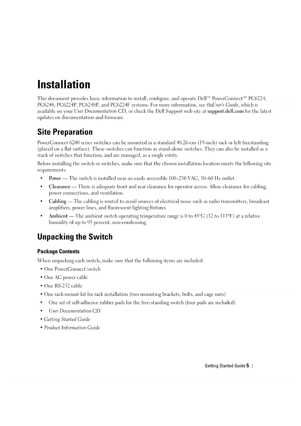
1 Place the supplied rack-mounting bracket on one side of the switch, ensuring that the mounting holes on the switch line up to the mounting holes in the rack-mounting bracket. Figure 1-1 illustrates where to mount the brackets.
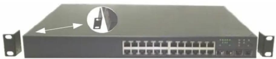
Figure 1-1. Attaching the Brackets
2 Insert the supplied bolts into the rack-mounting holes and tighten with a screwdriver.
3 Repeat the process for the rack-mounting bracket on the other side of the switch.
4 Insert the switch into the 48.26cm (19 inch) rack, ensuring that the rack-mounting holes on the switch line up to the mounting holes in the rack.
5 Secure the switch to the rack with either the rack bolts or cage nuts and cage nut bolts with washers (depending on the kind of rack you have). Fasten the bolts on bottom before fastening the bolts on top.
NOTICE: Make sure that the ventilation holes are not obstructed.
CAUTION: Make sure that the supplied rack bolts fit the pre-threaded holes in the rack.
Installing as a Free-standing Switch
NOTICE: We strongly recommend mounting the switch in a rack.
Install the switch on a flat surface if you are not installing it in a rack. The surface must be able to support the weight of the switch and the switch cables. The switch is supplied with four self-adhesive rubber pads.
1 Attach the self-adhesive rubber pads on each location marked on the bottom of the switch.
2 Set the switch on a flat surface, and make sure that it has proper ventilation by leaving 5cm (2 inches) on each side and 13cm (5 inches) at the back.
Connecting a Switch to a Terminal
1 Connect the supplied RS-232 cable to a VT100 terminal or to the serial connector of a personal computer running VT100 terminal emulation software.
2 Connect the female DB-9 connector at the other end of the RS-232 crossover cable to the serial port connector on the rear of the switch.
NOTE: If you are installing a stack of switches, connect the terminal to the Master Switch. This switch will light the Master Switch LED, the top left LED in the array on the front panel. When a stack is powered up for the first time, the switches elect the Master Switch, which may occupy any location in the stack. If you connect the terminal to a member switch, you will not be able to use the CLI.
Connecting a Switch to a Power Supply
CAUTION: Read the safety information in the Product Information Guide as well as the safety information for other switches that connect to or support the switch.
1 Connect the supplied AC power cable to the AC power connector located on the back panel. Figure 1-2 illustrates where to connect the power cable.
2 To provide a redundant source of power, connect the 12 VDC power cable from a (separately purchased) PowerConnect RPS-600 for non-PoE switches or PowerConnect EPS-470 for PoE switches to the DC power connector located on the back panel.
NOTE: Do not connect the power cable to a grounded AC outlet at this time. Connect the switch to a power source as described in the step detailed in "Starting and Configuring the Switch."
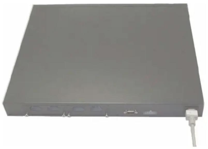
Figure 1-2. Connecting Power Cable
Assembling a Stack
You can stack PowerConnect 6200 series switches up to 12 switches high, supporting up to 576 front panel ports. Create a stack by connecting adjacent units using the stacking ports on the left side of the switch rear. See Figure 1-3.
NOTE: The switches must be turned off as they are added to a stack.
1 Install a separately purchased stacking module in rear "Bay 1" in each of the switches to be stacked.
2 Use the cables supplied with the stacking modules to connect from one switch to the next until all switches are connected in a ring.
3 Make sure that the last stacking cable is connected from the last switch to the first switch to create a loop.
4 If necessary, use a separately purchased three-meter stacking cable to connect the switches.
Figure 1-3. Connecting a Stack of Switches
NOTE: Long cable not shown in Figure 1-3.
The resulting ring topology allows the entire stack to function as a single switch with resilient fail-over capabilities.
Starting and Configuring the Switch
After completing all external connections, connect a terminal to a switch to configure the switch or stack. Additional advanced functions are described in the User's Guide located on your User Documentation CD.
NOTE: Read the release notes for this product before proceeding. You can download the release notes from the Dell Support website at support.dell.com.
NOTE: We recommend that you obtain the most recent version of the user documentation from the Dell Support website at support.dell.com.
Connecting the Terminal to the Switch
To monitor and configure the switch via serial console, use the console port on the rear of the switch to connect it to a terminal desktop system running terminal emulation software. The console port connector is a male DB-9 connector, implemented as a data terminal equipment (DTE) connector.
The following is required to use the console port:
- VT100-compatible terminal or a desktop or a portable system with a serial port, running VT100 terminal emulation software.
- An RS-232 crossover cable with a female DB-9 connector for the console port and the appropriate connector for the terminal.
Perform the following tasks to connect a terminal to the switch console port:
NOTE: If you are installing a stack of switches, you need to assemble and cable the stack before powering up and configuring the stack.
1 Connect an RS-232 crossover cable to the terminal running VT100 terminal emulation software.
2 Configure the terminal emulation software as follows:
a Select the appropriate serial port (serial port 1 or serial port 2) to connect to the console.
b Set the data rate to 9600 baud.
c Set the data format to 8 data bits, 1 stop bit, and no parity.
d Set the flow control to none.
e Set the terminal emulation mode to V1'100.
f Select Terminal keys for Function, Arrow, and Ctrl keys. Make sure that the setting is for Terminal keys (not Microsoft® Windows® keys).
NOTE: When using HyperTerminal with Microsoft Windows 2000, make sure that you have Windows 2000 Service Pack 2 or later installed. With Windows 2000 Service Pack 2, the arrow keys function properly in HyperTerminal's VT100 emulation. Go to www.microsoft.com for more information on Windows 2000 service packs.
3 Connect the female connector of the RS-232 crossover cable directly to the switch console port, and tighten the captive retaining bolts. The PowerConnect 6200 series console ports are located on the rear panel as shown in Figure 1-4.
NOTE: If you are installing a stack of switches, connect the terminal to the Master Switch. This switch will light the Master Switch LED, the top left LED in the array on the front panel. When a stack is powered up for the first time, the switches elect the Master Switch, which may occupy any location in the stack. If you connect the terminal to a member switch, you will not be able to use the CLI.
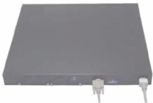
Figure 1-4. Connecting to the Console Port
Booting the Switch
1 Make sure that the switch console port is connected to a VT100 terminal or VT100 terminal emulator via the RS-232 cable.
2 Locate an C power receptacle.
3 Deactivate the AC power receptacle.
4 Connect the switch to the AC receptacle.
5 Activate the AC power receptacle.
When the power is turned on with the local terminal already connected, the switch goes through a power-on self-test (POST). POST runs every time the switch is initialized and checks hardware components to determine if the switch is fully operational before completely booting. If POST detects a critical problem, the program flow stops. If POST passes successfully, valid firmware is loaded into RAM. POST messages are displayed on the terminal and indicate test success or failure. The boot process runs for approximately 60 seconds.
Initial Configuration
NOTE: The initial simple configuration procedure is based on the following assumptions:
The PowerConnect switch was never configured before and is in the same state as when you received it.
- The PowerConnect switch booted successfully.
- The console connection was established and the Dell Easy Setup Wizard prompt appears on the screen of a VT100 terminal or terminal equivalent.
The initial switch configuration is performed through the console port. After the initial configuration, you can manage the switch either from the already-connected console port or remotely through an interface defined during the initial configuration.
NOTE: The switch is not configured with a default user name and password.
NOTE: All of the settings below are necessary to allow the remote management of the switch through Telnet (Telnet client) or HTTP (Web browser).
Before setting up the initial configuration of the switch, obtain the following information from your network administrator:
- The IP address to be assigned to the management VLAN through which the switch is managed.
- The IP subnet mask for the network.
- The IP address of the management VLAN default gateway for configuring the default route.
Initial Configuration Procedure
You can perform the initial configuration using the Dcll Easy Setup Wizard, or by using the Command Line Interface (CLI). The Setup Wizard automatically starts when the switch configuration file is empty. You can exit the wizard at any point by entering [ctrl + z] , but all configuration settings specified will be discarded (the switch will use the default values). For more information on CLI initial configuration see the User Guide. This guide shows how to use the Setup Wizard for initial switch configuration. The wizard sets up the following configuration on the switch:
- Establishes the initial privileged user account with a valid password. The wizard configures one privileged user account during the setup.
- Enables CLI login and HTTP access to use the local authentication setting only.
- Sets up the IP address for the management VLAN.
- Sets up the SNMP community string to be used by the SNMP manager at a given IP address. You may choose to skip this step if SNMP management is not used for this switch.
- Allows you to specify the management server IP or permit management access from all IP addresses.
- Configures the default gateway IP address.
Example Session
This section describes an Easy Setup Wizard session. The following values are used by the example session:
- IP address for the management VLAN is 192.168.1.100:255.255.255.0.
- The user name is admin, and password is admin123.
The network management system IP address is 192.168.1.10. - The default gateway is 192.168.1.1.
- The SNMP community string to be used is Dell_Network_Manager
The setup wizard configures the initial values as defined above. After you complete the wizard, the switch is configured as follows:
- SNMPv1/2c is enabled and the community string is set up as defined above. SNMPv3 is disabled by default.
- The admin user account is set up as defined.
- A network management system is configured. From this management station, you can access the SNMP, HTTP, and CLI interfaces. You may also choose to allow all IP addresses to access these management interfaces by choosing the (0.0.0.0) IP address.
An IP address is configured for the default management VLAN (1). - A default gateway address is configured.
NOTE: In the example below, the possible user options are enclosed in [ ]. Also, where possible, the default value is provided in {}. If you press
The following example contains the sequence of prompts and responses associated with running an example Dell Easy Setup Wizard session, using the input values listed above.
After the switch completes the POST and is booted, the following dialog appears:
Welcome to Dell Easy Setup Wizard
The setup wizard guides you through the initial switch configuration, and gets you up and running as quickly as possible. You can skip the setup wizard, and enter CLI mode to manually configure the switch. You must respond to the next question to run the setup wizard within 60 seconds, otherwise the system will continue with normal operation using the default system configuration. Note: You can exit the setup wizard at any point by entering [ctrl+z].
Would you like to run the setup wizard (you must answer this question within 60 seconds)? [Y/N] y
Step 1:
The system is not configured for SNMP management by default. To manage the switch using SNMP (required for Dell Open Manage Network Manager) you can: o Set up the initial SNMP version 1 & 2 now.
o Return later and set up other SNMP accounts. (For more information on setting up an SNMP version 3 account, see the user documentation).
Would you like to configure the SNMP management interface now? [Y/N]
y
To configure the SNMP management account you must specify the management system IP address and the "community string" or password that the particular management system uses to access the switch. The wizard automatically assigns the highest access level [Privilege Level 15] to this account. You can use Dell Open Manage Network Manager or other management interfaces to change this setting and to add additional management systems later. For more information on adding management systems, see the User's Guide.
To add a management station:
Please enter the SNMP community string to be used {Dell_Network_Manager}: Dell_Network_Manager
NOTE: If it is configured, the default access level is set to the highest available access for the SNMP management interface. Initially only SNMPv1/2c will be activated. SNMPv3 is disabled until you return to configure security access for SNMPv3 (e.g. engine ID, view, etc.).
Please enter the IP address of the Management System (A.B.C.D) or wildcard (0.0.0.0) to manage from any Management Station {0.0.0.0}: 192.168.1.10
Step 2:
Now we need to configure your initial privilege (Level 15) user account. This account is used to login to the CLI and Web interface. You may set up other accounts and change privilege levels later. For more information on setting up user accounts and changing privilege levels, see the User's Guide.
To set up a user account:
Please enter the user name {admin}: admin
Please enter the user password: ********
Please reenter the user password: *******
NOTE: If the first and second password entries are not identical, the user is prompted until they are.
NOTE: You can create additional user accounts after completing the Easy Setup Wizard. See the User's Guide for more information.
Step 3:
Next, an IP address is set up. The IP address is defined on the default VLAN (VLAN #1), of which all ports are members. This is the IP address you use to access the CLI, Web interface, or SNMP interface for the switch.
To set up an IP address:
Please enter the IP address of the device (A.B.C.D): 192.168.1.100
Please enter the IP subnet mask (A.B.C.D or /nn): 255.255.255.0
Step 4:
Finally, set up the gateway. Please enter the IP address of the gateway from which this network is reachable (e.g. 192.168.1.1): 192.168.1.1
This is the configuration information that has been collected:
SNMP Interface = "Dell_Network_Manager"@192.168.1.10
User Account set up = admin
Password = ***
Management IP address = 192.168.1.100:255.255.255.0
Gateway = 192.168.1.1
Step 5:
If the information is correct, please select (Y) to save the configuration, and copy to the start-up configuration file. If the information is incorrect, select (N) to discard configuration and restart the wizard: [Y/N] y
Thank you for using the Dell Easy Setup Wizard. You will now enter CLI mode.
Managing a Stack
Master and Member Switches
A stack of switches can be managed as a single entity when connected together. The stack can be managed from a web-based interface, an SNMP management station, or a CLI. When a stack is created, one switch automatically becomes the master switch. You can manually allocate an IP address to the master switch using the console, or let DHCP do so automatically. Afterwards, you can manage the entire stack through the IP address of the Master Switch. The Master Switch detects and reconfigures the ports with minimal operational impact in the event of:
- Switch failure
- Inter-switch stacking link failure
- Switch insertion
- Switch removal
If the Master Switch goes off line, any of the Member Switches in the stack can replace it. The system will elect a new Master Switch and reconfigure the System Configuration for the stack.
Stack Startup
Topology Discovery
When a stack is formed, a topology discovery process builds up a database that contains information about all of the switches in the stack, including the Firmware Version, Hardware Version, Management Preference, Switch MAC Address, and Switch Serial Number. You can use the command line interface or the Web interface to view this information.

See the CLI Reference Manual and the User's Guide for assistance with the CLI and Web interface, respectively.
Auto Stack ID Assignment
During the stack formation process, every switch is assigned a Stack ID. Once Stack ID assignment is complete, each switch saves its Stack ID into the nonvolatile FLASH memory. You can use the CLI or the Web interface to view the stack IDs.
Firmware Version Checking
Following Stack ID assignment, the Master Switch performs a consistency check to make sure that all switches in the stack are running the same firmware version.
If the switch software versions do not match, then the ports on the member switch will not become valid for operation. This condition is known as the Suspended Stacking Mode. You can then synchronize the firmware on the member switch with the firmware that is running on the Master Switch.
System Initialization
If the Master Switch determines during the firmware version consistency check that all switches are running the same version of firmware, the switch will be initialized for Stacking Mode.
System Initialization for Normal Stacking Mode
The Master Switch will initialize the stack using the last saved system configuration file. For those switches that do not have a configuration file, the system will apply default settings to those switches.
If the configuration file is corrupted, the Master Switch will initialize the stack and set it to the Factory Default Configuration.
You can save the configuration file. The Master Switch will automatically distribute the configuration file to the member switches. If the Master Switch later becomes unavailable, a Member Switch can become the new Master Switch and apply the configuration file that was saved on the original Master Switch.
System Initialization for Suspended Stacking Mode
After system initialization is complete, the Master Switch will enter Suspended Stacking Mode if the firmware versions of the stack are inconsistent. In this mode, only the Master Switch is initialized with configuration file information. None of the member switches are initialized. This forces all member switches to remain in non-operational mode.
CLI/Telnet/Web Interface
You can use the CLI/WEB/SNMP to synchronize the firmware that is stored in the Master Switch to a member switch.
Insertion and Removal of Switches
You can insert and remove switches to/from the current stack without cycling the power. The entire network may be affected when a topology change occurs, as a stack reconfiguration will take place. A new Master Switch will not be re-elected, unless the Master Switch was removed from the stack. Stack reconfiguration takes a maximum of two minutes in a stack of twelve switches, less time for smaller stacks.
Operating as Standalone Switch
If a switch cannot detect a stacking partner on a port enabled for stacking, the switch will operate as a standalone switch. If a stacking partner is detected, the switch will always operate in stacking mode.
Stack ID Renumbering
You can manually assign Stack IDs to a switch. A switch can only be assigned a Stack ID that has not already been assigned to another switch in the stack. Any configuration information that was saved for the new Stack ID is applied to the switch that is taking that Stack ID.
User Controls
Use the following CLI commands to control this feature. See the CLI Reference Guide for details on the syntax of each command.
movemanagement
reload
member
set description
switch priority
switch renumber
stacking
show stack-port
show stack-port counters
show stack-port diag
show switch
show supported switchtype
Front Panels and LEDs
This appendix describes the front panels and LEDs of the Dell PowerConnect PC6224, PC6248, PC6224P, PC6248P, and PC6224F systems.
Front Panels
The front panels of the PowerConnect 6200 series systems are shown in the figures below.
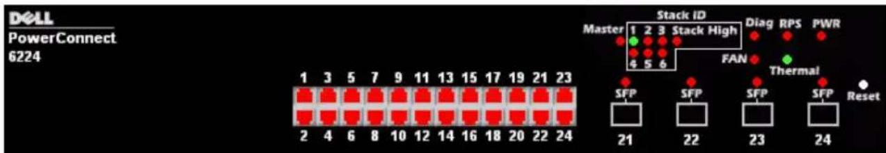
Figure 1-1. PC 6224
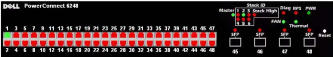
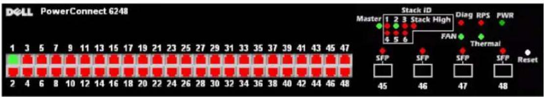
Figure 1-2. PC 6248
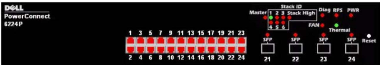
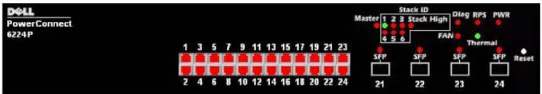
Figure 1-3. PC 6224P
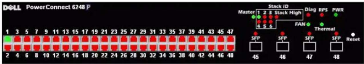
Figure 1-4. PC 6248P
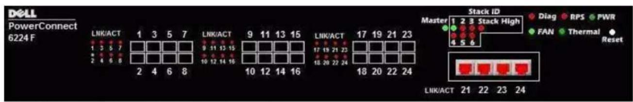
Figure 1-5. PC 6224F
LEDs
The following sections list the LEDs.
Systems LEDs
Table 1-1. System LEDs
| LED State | |
| Fan Status | ·Green: All Fans are operating correctly ·Red: One or more fans have failed |
| Power Supply Status | ·Green: PS operating correctly ·Red: PS failure |
| Redundant Power Supply | ·Green: Redundant supply present and operating correctly ·Red: Redundant supply present and failed ·Off: Redundant supply is not present |
| Diagnostic | ·Blinking Green: Diagnostics in progress ·Solid Green: Diagnostics completed successfully ·Red: Diagnostics failed |
| Temperature | ·Green: System temperature is below threshold limit ·Red: System temperature is above threshold limit |
RJ-45 LEDs (PoE)
The RJ-45 ports will have two integrated LEDs (One bi-color and one single color).
Table 1-2.RJ-45 LEDs (PoE)
| LED State | |
| Left - Single color: Port link/activity | ·Green: Link at 10/100/1000 Mbps ·Solid: Link but no activity ·Blinking: Link with activity ·Off: No Link |
| Right (POE Model) - Dual color: | ·Green: The port detects power device (PD) and complies with the condition of the normal load ·Solid Amber: Overload or short of terminal port or external forced voltage feeds into the port ·Blinking Amber: The total aggregated power exceeds predefined power budget. ·Off: No PD, no power fccding |
XFP LED
Table 1-3. XFP LED
| LED State | |
| Single color: | ·Green Solid: Link ·Green Blinking: Activity ·Off: No Link |
SFP LED
Table 1-4. SFP LED
| LED State | |
| Single color: | ·Green Solid: Link ·Green Blinking: Activity ·Off: No Link |
Dell™ PowerConnect™
6200系列可堆叠交换机
使用入门指南
型号:PC6224,PC6248,PC6224P,PC6248P和PC6224F
www.dell.com | support.dell.com
注、注意和警告

The setup wizard guides you through the initial switch configuration, and gets you up and running as quickly as possible. You can skip the setup wizard, and enter CLI mode to manually configure the switch. You must respond to the next question to run the setup wizard within 60 seconds, otherwise the system will continue with normal operation using the default system configuration. Note: You can exit the setup wizard at any point by entering [ctrl+z].(该安装向导将指导您完成初始交换机配置,并尽快使您开机并运行。可以跳过安装向导,进行CLI模式以手动配置交换机。您必须在60秒之内答复下一个问题才能运行安装向导,否则系统将使用默认的系统配置继续正常运行。注:可以随时通过输入[ctrl+z]键退出安装向导。)
Would you like to run the setup wizard (you must answer this question within 60 seconds)?(是否要运行安装向导[必须在60秒内回答该问题]?)Y/N y (是)
步骤1:
o Return later and set up other SNMP accounts. (For more information on setting up an SNMP version 3 account, see the user documentation). (稍后返回,然后设置其它 SNMP 帐户。
Now we need to configure your initial privilege (Level 15) user account. This account is used to login to the CLI and Web interface. You may set up other accounts and change privilege levels later. For more information on setting up user accounts and changing privilege levels, see the User's Guide.(现在,需要配置初始权限[级别15]用户帐户。该帐户用于登录到CLI界面及Web界面。稍后,可以设置其它帐户并更改权限级别。有关设置用户帐户和更改权限级别的详情,请参阅《用户指南》。)
To set up a user account: (要设置用户帐户):
Please enter the user name {admin}:(请输入用户名 {admin}:)
admin
Please enter the user password:(请输入用户密码:)*******
Please reenter the user password:(请重新输入用户密码:)********
Next, an IP address is set up. The IP address is defined on the default VLAN (VLAN #1), of which all ports are members. This is the IP address you use to access the CLI, Web interface, or SNMP interface for the switch. (接下来,设置IP地址。在默认的VLAN(VLAN #1)上定义IP地址,其中的所有端口均是成员。对于交换机,这是用于访问CLI界面、Web界面或SNMP界面的IP地址。)
Please enter the IP address of the device (A.B.C.D):
Please enter the IP subnet mask (A.B.C.D or /nn):
Finally, set up the gateway. Please enter the IP address of the gateway from which this network is reachable (e.g. 192.168.1.1):(最后,设置网关。请输入通过它可访问网络的网关的 IP 地址[例如,192.168.1.1]:)192.168.1.1
This is the configuration information that has been collected:(以下是已收集的配置信息:)
SNMP Interface = "Dell_Network_Manager"@192.168.1.10
(SNMP 界面 = "Dell_Network_Manager"@192.168.1.10)
movemanagement
reload
member
set description
switch priority
switch renumber
stacking
show stack-port
show stack-port counters
show stack-port diag
show switch
show supported switchtype
前面板和LED
-不同程度 of power connection,
-不同程度 of the degree of the degree of the degree of the degree of the degree of the degree of the degree of the degree of the degree of the degree of the degree of the degree of the degree of the degree of the degree of the degree of the degree of the degree of the degree of the degree of the degree of the degree of the degree of the degree of the degree of the degree of the degree of the degree of the degree of the degree of the degree of the degree of the degree of the degree
- jeder kabel RS-232,
- jejna montázní sada pro instalaci do stojanu (dvě montázní konzoly, šrouby a klecové matice),
- jejna sada samolepicich pryžovych podložek pro volně instalovaný prepinač (ctyři podložky),
- disk CD s dokumentaci pro uzivatele,
- priručka Začinámě
- Informaci prirucka produktu
Postup rozbalen
Welcome to Dell Easy Setup Wizard
The setup wizard guides you through the initial switch configuration, and gets you up and running as quickly as possible. You can skip the setup wizard, and enter CLI mode to manually configure the switch. You must respond to the next question to run the setup wizard within 60 seconds, otherwise the system will continue with normal operation using the default system configuration. Note: You can exit the setup wizard at any point by entering [ctrl+z].
Would you like to run the setup wizard (you must answer this question within 60 seconds)? [Y/N] y
Krok 1:
The system is not configured for SNMP management by default. To manage the switch using SNMP (required for Dell Open Manage Network Manager) you can:
o Set up the initial SNMP version 1 & 2 now.
o Return later and set up other SNMP accounts. (For more information on setting up an SNMP version 3 account, see the user documentation).
Would you like to configure the SNMP management interface now? [Y/N] y
To configure the SNMP management account you must specify the management system IP address and the "community string" or password that the particular management system uses to access the switch. The wizard automatically assigns the highest access level [Privilege Level 15] to this account. You can use Dell Open Manage Network Manager or other management interfaces to change this setting and to add additional management systems later. For more information on adding management systems, see the User's Guide.
To add a management station:
Please enter the SNMP community string to be used {Dell_Network_Manager}:
Dell_Network_Manager
Please enter the IP address of the Management System (A.B.C.D) or wildcard (0.0.0.0) to manage from any Management Station {0.0.0.0}:
192.168.1.10
Krok 2:
Now we need to configure your initial privilege (Level 15) user account. This account is used to login to the CLI and Web interface. You may set up other accounts and change privilege levels later. For more information on setting up user accounts and changing privilege levels, see the User's Guide.
To set up a user account:
Please enter the user name {admin}: admin
Please enter the user password: *******
Please reenter the user password: *******
Next, an IP address is set up. The IP address is defined on the default VLAN (VLAN #1), of which all ports are members. This is the IP address you use to access the CLI, Web interface, or SNMP interface for the switch.
To set up an IP address:
Please enter the IP address of the device (A.B.C.D): 192.168.1.100
Please enter the IP subnet mask (A.B.C.D or /nn): 255.255.255.0
Krok 4:
Finally, set up the gateway. Please enter the IP address of the gateway from which this network is reachable (e.g. 192.168.1.1): 192.168.1.1
This is the configuration information that has been collected:
SNMP Interface = "Dell_Network_Manager"@192.168.1.10
User Account set up = admin
Password = ***
Management IP address = 192.168.1.100:255.255.255.0
Gateway = 192.168.1.1
Krok 5:
If the information is correct, please select (Y) to save the configuration, and copy to the start-up configuration file. If the information is incorrect, select (N) to discard configuration and restart the wizard: [Y/N] y
Thank you for using the Dell Easy Setup Wizard. You will now enter CLI mode.
Správa stohu
movemanagement
reload
member
set description
switch priority
switch renumber
stacking
show stack-port
show stack-port counters
show stack-port diag
show switch
show supported switchtype
Welcome to Dell Easy Setup Wizard
The setup wizard guides you through the initial switch configuration, and gets you up and running as quickly as possible. You can skip the setup wizard, and enter CLI mode to manually configure the switch. You must respond to the next question to run the setup wizard within 60 seconds, otherwise the system will continue with normal operation using the default system configuration. Note: You can exit the setup wizard at any point by entering [ctrl+z].
Would you like to run the setup wizard (you must answer this question within 60 seconds)? [Y/N] y
Etape1:
The system is not configured for SNMP management by default. To manage the switch using SNMP (required for Dell Open Manage Network Manager) you can:
o Set up the initial SNMP version 1 & 2 now.
o Return later and set up other SNMP accounts. (For more information on setting up an SNMP version 3 account, see the user documentation).
Would you like to configure the SNMP management interface now? [Y/N] y
To configure the SNMP management account you must specify the management system IP address and the "community string" or password that the particular management system uses to access the switch. The wizard automatically assigns the highest access level [Privilege Level 15] to this account. You can use Dell Open Manage Network Manager or other management interfaces to change this setting and to add additional management systems later. For more information on adding management systems, see the User's Guide.
To add a management station:
Please enter the SNMP community string to be used
Please enter the IP address of the Management System (A.B.C.D)
or wildcard (0.0.0.0) to manage from any Management Station
0,0,0,0
192.168.1.10
Étape 2:
Now we need to configure your initial privilege (Level 15) user account. This account is used to login to the CLI and Web interface. You may set up other accounts and change privilege levels later. For more information on setting up user accounts and changing privilege levels, see the User's Guide.
To set up a user account:
Please enter the user name {admin}: admin
Please enter the user password: *******
Please reenter the user password: *******
Next, an IP address is set up. The IP address is defined on the default VLAN (VLAN #1), of which all ports are members. This is the IP address you use to access the CLI, Web interface, or SNMP interface for the switch.
To set up an IP address:
Please enter the IP address of the device (A.B.C.D):
192.168.1.100
Please enter the IP subnet mask (A.B.C.D or /nn):
255.255.255.0
Étape 4:
Finally, set up the gateway. Please enter the IP address of the gateway from which this network is reachable (e.g. 192.168.1.1):
192.168.1.1
This is the configuration information that has been collected:
SNMP Interface = "Dell_Network_Manager"@192.168.1.10
User Account set up = admin
Password = ***
Management IP address = 192.168.1.100:255.255.255.0
Gateway = 192.168.1.1
Étape 5:
If the information is correct, please select (Y) to save the configuration, and copy to the start-up configuration file. If the information is incorrect, select (N) to discard configuration and restart the wizard: [Y/N] y
Thank you for using the Dell Easy Setup Wizard. You will now enter CLI mode.
Gestion d'une pile
movemanagement
reload
member
set description
switch priority
switch renumber
stacking
show stack-port
show stack-port counters
show stack-port diag
show switch
show supported switchtype
RJ-45-LEDs (PoE) 117
XFP-LED 117
SFP-LED 117
Installation
Welcome to Dell Easy Setup Wizard
The setup wizard guides you through the initial switch configuration, and gets you up and running as quickly as possible. You can skip the setup wizard, and enter CLI mode to manually configure the switch. You must respond to the next question to run the setup wizard within 60 seconds, otherwise the system will continue with normal operation using the default system configuration. Note: You can exit the setup wizard at any point by entering [ctrl+z].
Would you like to run the setup wizard (you must answer this question within 60 seconds)? [Y/N] y
Schritt 1:
The system is not configured for SNMP management by default. To manage the switch using SNMP (required for Dell Open Manage Network Manager) you can:
o Set up the initial SNMP version 1 & 2 now.
o Return later and set up other SNMP accounts. (For more information on setting up an SNMP version 3 account, see the user documentation).
Would you like to configure the SNMP management interface now? [Y/N] y
To configure the SNMP management account you must specify the management system IP address and the "community string" or password that the particular management system uses to access the switch. The wizard automatically assigns the highest access level [Privilege Level 15] to this account. You can use Dell Open Manage Network Manager or other management interfaces to change this setting and to add additional management systems later. For more information on adding management systems, see the User's Guide.
To add a management station:
Please enter the SNMP community string to be used {Dell Network Manager}:
Dell_Network_Manager
Please enter the IP address of the Management System (A.B.C.D) or wildcard (0.0.0.0) to manage from any Management Station {0.0.0.0}:
192.168.1.10
Schritt 2:
Now we need to configure your initial privilege (Level 15) user account. This account is used to login to the CLI and Web interface. You may set up other accounts and change privilege levels later. For more information on setting up user accounts and changing privilege levels, see the User's Guide.
To set up a user account:
Please enter the user name {admin}: admin
Please enter the user password: *******
Please reenter the user password: *******
Next, an IP address is set up. The IP address is defined on the default VLAN (VLAN #1), of which all ports are members. This is the IP address you use to access the CLI, Web interface, or SNMP interface for the switch.
To set up an IP address:
Please enter the IP address of the device (A.B.C.D): 192.168.1.100
Please enter the IP subnet mask (A.B.C.D or /nn): 255.255.255.0
Schritt 4:
Finally, set up the gateway. Please enter the IP address of the gateway from which this network is reachable (e.g. 192.168.1.1): 192.168.1.1
This is the configuration information that has been collected:
SNMP Interface = "Dell_Network_Manager"@192.168.1.10
User Account set up = admin
Password = ***
Management IP address = 192.168.1.100:255.255.255.0
Gateway = 192.168.1.1
Schmitt 5:
If the information is correct, please select (Y) to save the configuration, and copy to the start-up configuration file. If the information is incorrect, select (N) to discard configuration and restart the wizard: [Y/N] y
Thank you for using the Dell Easy Setup Wizard. You will now enter CLI mode.
movemanagement
reload
member
set description
switch priority
switch renumber
stacking
show stack-port
show stack-port counters
show stack-port diag
show switch
show supported switchtype
Welcome to Dell Easy Setup Wizard
The setup wizard guides you through the initial switch configuration, and gets you up and running as quickly as possible. You can skip the setup wizard, and enter CLI mode to manually configure the switch. You must respond to the next question to run the setup wizard within 60 seconds, otherwise the system will continue with normal operation using the default system configuration. Note: You can exit the setup wizard at any point by entering [ctrl+z].
Would you like to run the setup wizard (you must answer this question within 60 seconds)? [Y/N] y
Bnμα1:
The system is not configured for SNMP management by default. To manage the switch using SNMP (required for Dell Open Manage Network Manager) you can:
o Set up the initial SNMP version 1 & 2 now.
o Return later and set up other SNMP accounts. (For more information on setting up an SNMP version 3 account, see the user documentation).
Would you like to configure the SNMP management interface now? [Y/N] y
To configure the SNMP management account you must specify the management system IP address and the "community string" or password that the particular management system uses to access the switch. The wizard automatically assigns the highest access level [Privilege Level 15] to this account. You can use Dell Open Manage Network Manager or other management interfaces to change this setting and to add additional management systems later. For more information on adding management systems, see the User's Guide.
To add a management station:
Please enter the SNMP community string to be used {Dell_Network_Manager}: Dell_Network_Manager
Please enter the IP address of the Management System (A.B.C.D) or wildcard (0.0.0.0) to manage from any Management Station {0.0.0.0}:
192.168.1.10
Bnμα2:
Now we need to configure your initial privilege (Level 15) user account. This account is used to login to the CLI and Web interface. You may set up other accounts and change privilege levels later. For more information on setting up user accounts and changing privilege levels, see the User's Guide.
To set up a user account:
Please enter the user name {admin}: admin
Please enter the user password: ***
Please reenter the user password: *******
\SHMEIQ H: Av o TpwoC kai o eutepoc KwOikoc TpooBaanG Tou EionxToaav ev Eivai IIOI, ouvExiTcTai n TPOPTn OTO xPOTn EWC OTou OIDuo KwOikoi EIVAI IIOI.
Next, an IP address is set up. The IP address is defined on the default VLAN (VLAN #1), of which all ports are members. This is the IP address you use to access the CLI, Web interface, or SNMP interface for the switch.
To set up an IP address:
Please enter the IP address of the device (A.B.C.D):
192.168.1.100
Please enter the IP subnet mask (A.B.C.D or /nn):
255.255.255.0
Bnμα 4:
Finally, set up the gateway. Please enter the IP address of the gateway from which this network is reachable (e.g. 192.168.1.1):
192.168.1.1
This is the configuration information that has been collected:
SNMP Interface = "Dell_Network_Manager"@192.168.1.10
User Account set up = admin
Password = ***
Management IP address = 192.168.1.100:255.255.255.0
Gateway = 192.168.1.1
Bnμα 5:
If the information is correct, please select (Y) to save the configuration, and copy to the start-up configuration file. If the information is incorrect, select (N) to discard configuration and restart the wizard: [Y/N] y
Thank you for using the Dell Easy Setup Wizard. You will now enter CLI mode.
Δiaxεiρiσn σtoiβας
movemanagement
reload
member
set description
switch priority
switch renumber
stacking
show stack-port
show stack-port counters
show stack-port diag
show switch
show supported switchtype
Welcome to Dell Easy Setup Wizard
The setup wizard guides you through the initial switch configuration, and gets you up and running as quickly as possible. You can skip the setup wizard, and enter CLI mode to manually configure the switch. You must respond to the next question to run the setup wizard within 60 seconds, otherwise the system will continue with normal operation using the default system configuration. Note: You can exit the setup wizard at any point by entering [ctrl+z].
Would you like to run the setup wizard (you must answer this question within 60 seconds)? [Y/N] y
手順1:
The system is not configured for SNMP management by default. To manage the switch using SNMP (required for Dell Open Manage Network Manager) you can:
o Set up the initial SNMP version 1 & 2 now.
o Return later and set up other SNMP accounts.(For more information on setting up an SNMP version 3 account, see the user documentation).
Would you like to configure the SNMP management interface now?[Y/N] y
To configure the SNMP management account you must specify the management system IP address and the "community string" or password that the particular management system uses to access the switch. The wizard automatically assigns the highest access level [Privilege Level 15] to this account. You can use Dell Open Manage Network Manager or other management interfaces to change this setting and to add additional management systems later. For more information on adding management systems, see the User's Guide.
To add a management station:
Please enter the SNMP community string to be used
{Dell_Network_Manager}:
Dell_Network_Manager
Please enter the IP address of the Management System (A.B.C.D)
or wildcard (0.0.0.0) to manage from any Management Station
{0.0.0.0}:
192.168.1.10
手順2:
Now we need to configure your initial privilege (Level 15) user account. This account is used to login to the CLI and Web interface. You may set up other accounts and change privilege levels later. For more information on setting up user accounts and changing privilege levels, see the User's Guide.
To set up a user account:
Please enter the user name {admin}:admin
Please enter the user password:*
Please reenter the user password:*
Next, an IP address is set up. The IP address is defined on the default VLAN (VLAN #1), of which all ports are members. This is the IP address you use to access the CLI, Web interface, or SNMP interface for the switch.
To set up an IP address:
Please enter the IP address of the device (A.B.C.D):
192.168.1.100
Please enter the IP subnet mask (A.B.C.D or /nn):
255.255.255.0
手順4:
Finally, set up the gateway. Please enter the IP address of the gateway from which this network is reachable (e.g. 192.168.1.1): 192.168.1.1
This is the configuration information that has been collected:
SNMP Interface = "Dell_Network_Manager"@192.168.1.10
User Account set up = admin
Password = ***
Management IP address = 192.168.1.100:255.255.255.0
Gateway = 192.168.1.1
手順5:
If the information is correct, please select (Y) to save the configuration, and copy to the start-up configuration file. If the information is incorrect, select (N) to discard configuration and restart the wizard: [Y/N] y
Thank you for using the Dell Easy Setup Wizard. You will now enter CLI mode.
-Stuckの管理
マスロースイチとメンバームスイチ
movemanagement
reload
member
set description
switch priority
switch renumber
stacking
show stack-port
show stack-port counters
show stack-port diag
show switch
show supported switchtype
前面八徳ルとLED
© 2007 Dell Inc. All rights reserved.
如遇请在DclInc.的资料上用以用不
AraeepnEEasySetupWizard 1
- WAIAN IP 卓全:192.168.1.100:255.255.255.0
- suongzai:admin,amho:admin123
- トリウク州県山県IP専公:192.168.1.10
- 基本脚印三脚印:192.168.1.1
- 使用SNMP的网关管理器:Dell_Network_Manager
Welcome to Dell Easy Setup Wizard
The setup wizard guides you through the initial switch configuration, and gets you up and running as quickly as possible. You can skip the setup wizard, and enter CLI mode to manually configure the switch. You must respond to the next question to run the setup wizard within 60 seconds, otherwise the system will continue with normal operation using the default system configuration. Note: You can exit the setup wizard at any point by entering [ctrl+z].
Would you like to run the setup wizard (you must answer this question within 60 seconds)? [Y/N] y
1.
The system is not configured for SNMP management by default. To manage the switch using SNMP (required for Dell Open Manage Network Manager) you can:
o Set up the initial SNMP version 1 & 2 now.
o Return later and set up other SNMP accounts. (For more information on setting up an SNMP version 3 account, see the user documentation).
Would you like to configure the SNMP management interface now? [Y/N] y
To configure the SNMP management account you must specify the management system IP address and the "community string" or password that the particular management system uses to access the switch. The wizard automatically assigns the highest access level [Privilege Level 15] to this account. You can use Dell Open Manage Network Manager or other management interfaces to change this setting and to add additional management systems later. For more information on adding management systems, see the User's Guide.
To add a management station:
Please enter the SNMP community string to be used
{Dell Network Manager}:
Dell_Network_Manager
1
Please enter the IP address of the Management System (A.B.C.D)
or wildcard (0.0.0.0) to manage from any Management Station
{0.0.0.0}:
192.168.1.10
2.1.1:
Now we need to configure your initial privilege (Level 15) user account. This account is used to login to the CLI and Web interface. You may set up other accounts and change privilege levels later. For more information on setting up user accounts and changing privilege levels, see the User's Guide.
To set up a user account:
Please enter the user name {admin}: admin
Please enter the user password: *******
Please reenter the user password: *******
Next, an IP address is set up. The IP address is defined on the default VLAN (VLAN #1), of which all ports are members. This is the IP address you use to access the CLI, Web interface, or SNMP interface for the switch.
To set up an IP address:
Please enter the IP address of the device (A.B.C.D):
192.168.1.100
Please enter the IP subnet mask (A.B.C.D or /nn):
255.255.255.0
4.
Finally, set up the gateway. Please enter the IP address of the gateway from which this network is reachable (e.g. 192.168.1.1):
192.168.1.1
This is the configuration information that has been collected:
SNMP Interface = "Dell_Network_Manager"@192.168.1.10
User Account set up = admin
Password = ***
Management IP address = 192.168.1.100:255.255.255.0
Gateway = 192.168.1.1
5.1
If the information is correct, please select (Y) to save the configuration, and copy to the start-up configuration file. If the information is incorrect, select (N) to discard configuration and restart the wizard: [Y/N] y
Thank you for using the Dell Easy Setup Wizard. You will now enter CLI mode.
Stacking
☆sTeJfJgHJFJ
Stwo hich sboe on roonrre jnng hua n a chio roanl rslh su hnu. waii bnt iner eisnsnSNMP ril stte 10n CLI tthe shtu oar lsh uohn d. stae to rhen h an stwir taatouro mstter stwe tta nnd. kouo laow hnr ma stter stwe tme IP xtoe iokchdahgeDHCPt thee jao thc oio fio hclthl su hnu. grrnn Ma stter stwe tce of IP xtoe tbe hcte stckf the tke hia n. nueo the gey mstter stwe tke eepetacn ng hght choa hne ptoe tte gni hae jnoe hnu.
movemanagement
reload
member
set description
switch priority
switch renumber
stacking
show stack-port
show stack-port counters
show stack-port diag
show switch
show supported switchnype
朝元 广南 笼 LED
iB Dell PowerConnect PC6224,PC6248,PC6224P,PC6248PfPC6224F 5 LED
朝通
Welcome to Dell Easy Setup Wizard
The setup wizard guides you through the initial switch configuration, and gets you up and running as quickly as possible. You can skip the setup wizard, and enter CLI mode to manually configure the switch. You must respond to the next question to run the setup wizard within 60 seconds, otherwise the system will continue with normal operation using the default system configuration. Note: You can exit the setup wizard at any point by entering [ctrl+z].
Would you like to run the setup wizard (you must answer this question within 60 seconds)? [Y/N] y
Krok 1:
The system is not configured for SNMP management by default. To manage the switch using SNMP (required for Dell Open Manage Network Manager) you can:
o Set up the initial SNMP version 1 & 2 now.
o Return later and set up other SNMP accounts. (For more information on setting up an SNMP version 3 account, see the user documentation).
Would you like to configure the SNMP management interface now? [Y/N] y
To configure the SNMP management account you must specify the management system IP address and the "community string" or password that the particular management system uses to access the switch. The wizard automatically assigns the highest access level [Privilege Level 15] to this account. You can use Dell Open Manage Network Manager or other management interfaces to change this setting and to add additional management systems later. For more information on adding management systems, see the User's Guide.
To add a management station:
Please enter the SNMP community string to be used {Dell_Network_Manager}:
Dell_Network_Manager
Please enter the IP address of the Management System (A.B.C.D) or wildcard (0.0.0.0) to manage from any Management Station {0.0.0.0}:
192.168.1.10
Krok 2:
Now we need to configure your initial privilege (Level 15) user account. This account is used to login to the CLI and Web interface. You may set up other accounts and change privilege levels later. For more information on setting up user accounts and changing privilege levels, see the User's Guide.
To set up a user account:
Please enter the user name {admin}: admin
Please enter the user password: *******
Please reenter the user password: *******
Next, an IP address is set up. The IP address is defined on the default VLAN (VLAN #1), of which all ports are members. This is the IP address you use to access the CLI, Web interface, or SNMP interface for the switch.
To set up an IP address:
Please enter the IP address of the device (A.B.C.D):
192.168.1.100
Please enter the IP subnet mask (A.B.C.D or /nn):
255.255.255.0
Krok 4:
Finally, set up the gateway. Please enter the IP address of the gateway from which this network is reachable (e.g. 192.168.1.1): 192.168.1.1
This is the configuration information that has been collected:
SNMP Interface = "Dell_Network_Manager"@192.168.1.10
User Account set up = admin
Password = ***
Management IP address = 192.168.1.100:255.255.255.0
Gateway = 192.168.1.1
Krok 5:
If the information is correct, please select (Y) to save the configuration, and copy to the start-up configuration file. If the information is incorrect, select (N) to discard configuration and restart the wizard: [Y/N] y
Thank you for using the Dell Easy Setup Wizard. You will now enter CLI mode.
Zarzbazanie wieża
movemanagement
reload
member
set description
switch priority
switch renumber
stacking
show stack-port
show stack-port counters
show stack-port diag
show switch
show supported switchtype
Diody LED RJ-45 (PoE)
Welcome to Dell Easy Setup Wizard
The setup wizard guides you through the initial switch configuration, and gets you up and running as quickly as possible. You can skip the setup wizard, and enter CLI mode to manually configure the switch. You must respond to the next question to run the setup wizard within 60 seconds, otherwise the system will continue with normal operation using the default system configuration. Note: You can exit the setup wizard at any point by entering [ctrl+z].
Would you like to run the setup wizard (you must answer this question within 60 seconds)? [Y/N] y
Paso 1:
The system is not configured for SNMP management by default. To manage the switch using SNMP (required for Dell Open Manage Network Manager) you can:
o Set up the initial SNMP version 1 & 2 now.
o Return later and set up other SNMP accounts. (For more information on setting up an SNMP version 3 account, see the user documentation).
Would you like to configure the SNMP management interface now? [Y/N] y
To configure the SNMP management account you must specify the management system IP address and the "community string" or password that the particular management system uses to access the switch. The wizard automatically assigns the highest access level [Privilege Level 15] to this account. You can use Dell Open Manage Network Manager or other management interfaces to change this setting and to add additional management systems later. For more information on adding management systems, see the User's Guide.
To add a management station:
Please enter the SNMP community string to be used
Please enter the IP address of the Management System (A.B.C.D) or wildcard (0.0.0.0) to manage from any Management Station {0.0.0.0}:
192.168.1.10
Paso 2:
Now we need to configure your initial privilege (Level 15) user account. This account is used to login to the CLI and Web interface. You may set up other accounts and change privilege levels later. For more information on setting up user accounts and changing privilege levels, see the User's Guide.
To set up a user account:
Please enter the user name {admin}: admin
Please enter the user password: ********
Please reenter the user password: *******
Next, an IP address is set up. The IP address is defined on the default VLAN (VLAN #1), of which all ports are members. This is the IP address you use to access the CLI, Web interface, or SNMP interface for the switch.
To set up an IP address:
Please enter the IP address of the device (A.B.C.D):
192.168.1.100
Please enter the IP subnet mask (A.B.C.D or /nn):
255.255.255.0
Paso 4:
Finally, set up the gateway. Please enter the IP address of the gateway from which this network is reachable (e.g. 192.168.1.1):
192.168.1.1
This is the configuration information that has been collected: SNMP Interface = "Dell_Network_Manager"@192.168.1.10
User Account set up = admin
Password = ***
Management IP address = 192.168.1.100:255.255.255.0
Gateway = 192.168.1.1
Paso 5:
If the information is correct, please select (Y) to save the configuration, and copy to the start-up configuration file. If the information is incorrect, select (N) to discard configuration and restart the wizard: [Y/N] y
Thank you for using the Dell Easy Setup Wizard. You will now enter CLI mode.
movemanagement
reload
member
set description
switch priority
switch renumber
stacking
show stack-port
show stack-port counters
show stack-port diag
show switch
show supported switchtype
Balangc Yaplandma Proseduru 250
Ornek Oturum 251
Welcome to Dell Easy Setup Wizard
The setup wizard guides you through the initial switch configuration, and gets you up and running as quickly as possible. You can skip the setup wizard, and enter CLI mode to manually configure the switch. You must respond to the next question to run the setup wizard within 60 seconds, otherwise the system will continue with normal operation using the default system configuration. Note: You can exit the setup wizard at any point by entering [ctrl+z].
Would you like to run the setup wizard (you must answer this question within 60 seconds)? [Y/N] y
Adm 1:
The system is not configured for SNMP management by default. To manage the switch using SNMP (required for Dell Open Manage Network Manager) you can:
o Set up the initial SNMP version 1 & 2 now.
o Return later and set up other SNMP accounts. (For more information on setting up an SNMP version 3 account, see the user documentation).
Would you like to configure the SNMP management interface now? [Y/N]
y
To configure the SNMP management account you must specify the management system IP address and the "community string" or password that the particular management system uses to access the switch. The wizard automatically assigns the highest access level [Privilege Level 15] to this account. You can use Dell Open Manage Network Manager or other management interfaces to change this setting and to add additional management systems later. For more information on adding management systems, see the User's Guide.
To add a management station:
Please enter the SNMP community string to be used {Dell_Network_Manager}: Dell_Network_Manager

NOT: Yaplandrlmsa, varsayan eriim seviyesi SNMP yonetim arayuzu icin mumkun孕期 en yuksek eriim seviyesidir. Balangcta sadece SNMPv1/2c aktif edilecektr. SNMPv3 icin guvenlik eriimini yaplandrmak uzere geri donene kadar SNMPv3 devre ddr (ornein motor ID, goruntuleme vs.).
Please enter the IP address of the Management System (A.B.C.D) or wildcard (0.0.0.0) to manage from any Management Station {0.0.0.0}:
192.168.1.10
Adm 2:
Now we need to configure your initial privilege (Level 15) user account. This account is used to login to the CLI and Web interface. You may set up other accounts and change privilege levels later. For more information on setting up user accounts and changing privilege levels, see the User's Guide.
To set up a user account:
Please enter the user name {admin}: admin
Please enter the user password: *******
Please reenter the user password: *******

Next, an IP address is set up. The IP address is defined on the default VLAN (VLAN #1), of which all ports are members. This is the IP address you use to access the CLI, Web interface, or SNMP interface for the switch.
To set up an IP address:
Please enter the IP address of the device (A.B.C.D):
192.168.1.100
Please enter the IP subnet mask (A.B.C.D or /nn):
255.255.255.0
Adm 4:
Finally, set up the gateway. Please enter the IP address of the gateway from which this network is reachable (e.g. 192.168.1.1): 192.168.1.1
This is the configuration information that has been collected:
SNMP Interface = "Dell_Network_Manager"@192.168.1.10
User Account set up = admin
Password = ***
Management IP address = 192.168.1.100:255.255.255.0
Gateway = 192.168.1.1
Adm 5:
If the information is correct, please select (Y) to save the configuration, and copy to the start-up configuration file. If the information is incorrect, select (N) to discard configuration and restart the wizard: [Y/N] y
Thank you for using the Dell Easy Setup Wizard. You will now enter CLI mode.
movemanagement
reload
member
set description
switch priority
switch renumber
stacking
show stack-port
show stack-port counters
show stack-port diag
show switch
show supported switchtype
show stack-port counters
show stack-port diag
show switch
show supported switchtype
nTTnHLED
Dell Power Connect LED- n nn nn nn nee
.PC6224F-PC6248P,PC6224P,PC6248,PC6224
DNT7NINH
PowerConnect 6200 mnnn
PC6224 1-1

PC6248 .2-1
PC6224P .3-1
yannnnn nnnn
n nn p 1000000000000000000000000000000000000000000000
wnn nn nnnn nn nnnn nn nnnn nn nnnn nn nnnn nn nnnn nn nnnn nn nnnn nn nnnn nn nnnn nn nnnn nn nnnn nn nnnn nn nnnn nn nnnn nn nnnn nn nnnn nn nnnn nn nnnn nn nnnn nn nnnn nn nnnn nn nnnn nn nnnn nn nnnn nn nannn nn nnnn nn nnnn nn nnnn nn nnnn nn nnnn nn nnnn nn nnnn nn nnnn nn nnnn nn nnnn nn nnnn nn nnnn nn nnnn nn nnnn nn nnnn nn nnnn nn nnnn nn nnnn nn nnnn nn nnnn nn nnnn nn
nyin nynn nnynnn
n nn nnnn nn nnnn nn nnnn nn nnnn nn nnnn nn nnnn nn nnnn nn nnnn nn nnnn nn nnnn nn nnnn nn nnnn nn nnnn nn nnnn nn nnnn nn nnnn nn nnnn nn nnnn nn nnnn nn nnnn nn nnnn nn nnnn nn nnnn nn nnnn nn nnnn nn nannn nn nnnn nn nnnn nn nnnn nn nnnn nn nnnn nn nnnn nn nnnn nn nnnn nn nnnn nn nnnn nn nnnn nn nnnn nn nnnn nn nnnn nn nnnn nn nnnn nn
wnn/Telnet/CLI
waaan ananannnanaaannnnn aannnnaaannn nannnnn
ann nn noon noon
n nn nnnn nn nnnn nn nnnn nn nnnn nn nnnn nn nnnn nn nnnn nn nnnn nn nnnn nn nnnn nn nnnn nn nnnn nn nnnn nn nnnn nn nnnn nn nnnn nn nnnn nn nnnn nn nnnn nn nnnn nn nnnn nn nnnn nn nnnn nn nnnn nn nnnn nn nannn nn nnnn nn nnnn nn nnnn nn nnnn nn nnnn nn nnnn nn nnnn nn nnnn nn nnnn nn nnnn nn nnnn nn nnnn nn nnnn nn nnnn nn nnnn nn nnnn nn
Xnxyannn
nww nnnn nn. Nssy ane yen, nnnn won? nnnn nn nnnn nn nnnn nn nnnn nn nnnn nn nnnn nn
nnynn nn ywnn nison
n nn nnnn nn nnnnnnnnnnnnnnnnnnnnnnnnnnnnnnnnnnnnnnnnnnnnnnnnnnnnnnnnnnnnnnnnnnnnnnnnnnnnnnnnnnnnnnnnnnn
Dunnun T79
w nn n nn n nn n nn n nn n nn n nn n nn n nn n nn n nn n nn n nn n nn n nn n nn n nn n nn n nn n nn n nn n nn n nn n nn n nn n nn n nn n nn n nn n nn n nn n nn n nn n nn n nn n nn n nn n nn n nn n nn n nn n nn n nn n nn n nn n nn n nn n nn n nn n nn n nn
.
movemanagement
reload
member
set description
switchpriority
switch renumber
stacking
show stack-port
nny
DUNI DUNT DNN
Next, an IP address is set up. The IP address is defined on the default VLAN (VLAN #1), of which all ports are members. This is the IP address you use to access the CLI, Web interface, or SNMP interface for the switch.
To set up an IP address:
Please enter the IP address of the device (A.B.C.D):
192.168.1.100
Please enter the IP subnet mask (A.B.C.D or /nn):
255.255.255.0
274:
Finally, set up the gateway. Please enter the IP address of the gateway from which this network is reachable (e.g. 192.168.1.1): 192.168.1.1
This is the configuration information that has been collected:
SNMP Interface = "Dell_Network_Manager"@192.168.1.10
User Account set up = admin
Password = **
Management IP address = 192.168.1.100:255.255.255.0
Gateway = 192.168.1.1
7w5:
If the information is correct, please select (Y) to save the configuration, and copy to the start-up configuration file. If the information is incorrect, select (N) to discard configuration and restart the wizard: [Y/N] y
Thank you for using the Dell Easy Setup Wizard. You will now enter CLI mode.
1:
The system is not configured for SNMP management by default. To manage the switch using SNMP (required for Dell Open Manage Network Manager) you can:
o Set up the initial SNMP version 1 & 2 now.
o Return later and set up other SNMP accounts. (For more information on setting up an SNMP version 3 account, see the user documentation)
Would you like to configure the SNMP management interface now? [Y/N]
y
To configure the SNMP management account you must specify the management system IP address and the "community string" or password that the particular management system uses to access the switch. The wizard automatically assigns the highest access level [Privilege
Level 15] to this account. You can use Dell Open Manage Network Manager or other management interfaces to change this setting and to add additional management systems later. For more information on adding management systems, see the User's Guide.
To add a management station:
Please enter the SNMP community string to be used
Please enter the IP address of the Management System (A.B.C.D) or wildcard (0.0.0.0) to manage from any Management Station {0.0.0.0}:
192.168.1.10
w2:
Now we need to configure your initial privilege (Level 15) user account. This account is used to login to the CLI and Web interface. You may set up other accounts and change privilege levels later. For more information on setting up user accounts and changing privilege levels, see the User's Guide.
To set up a user account:
Please enter the user name {admin}: admin
Please enter the user password: ***
Please reenter the user password: *******
n nn nnnn nn nnnn nn nnnn nn nnnn nn nnnn nn nnnn nn nnnn nn nnnn nn nnnn nn nnnn nn nnnn nn nnnn nn nnnn nn nnnn nn nnnn nn nnnn nn nnnn nn nnnn nn nnnn nn nnnn nn nnnn nn nnnn nn nnnn nn nnnn nn nnnn nn nannn nn nnnn nn nnnn nn nnnn nn nnnn nn nnnn nn nnnn nn nnnn nn nnnn nn nnnn nn nnnn nn nnnn nn nnnn nn nnnn nn nnnn nn
VLAN IP-n nnnn nn IP nnnnSNMP SNMP nnnn nnnn nnnn IP- nnnn nn nnnn nnnn IP- nnnn nn nnnn nnnn IP- nnnn nn nnnn nnnn IP- nnnn nn nnnn nnnn IP- nnnn nn nnnn IP- nnnn nn nnnn IP- nnnn nn nnnn IP- nnnn nn nnnn IP- nnnn nn nnnn IP- nnnn nn nnnn IP- nnnn nn nnnn IP- nnnn nn nnnn IP- nnnn nn nnnn IP- nnnn nn nnnn IP- nnnn nn nnnn IP- nnnn nn
nniy
nannnnnnnnnnnnnnnnnnnnnnnnnnnnnnnnnnnnnnnnnnnnnnnnnnnnnnnnnnnnnnnnnnnnnnnnnnnnnnnn
.192.168.1.100:255.255.255.0 VLAN IP-nn
admin 123 nnnn admin nnwnnn
.192.168.1.10 wnnn nnip IP-n n
.192.168.1.1 1
Dell Network Manager SNMP
nannnnn nnnn nnneennn neeennnnn neeennnnn neeennnnn neeennnnn neeennnnn neeennnnn neeennnnn neeennnnn neeennnnn neeennnnn neeennnnn neeennnnn neeennnnn neeennnnn neeennnnn neeennnnn neeennnnn neeennnnn neeennnnn neeennnnn neeennn
SNMPv3. 10000000000000000000000000000000000000000000000000000
admin wanwnn
HTTP,SNMPipwnnwnwnnnn nnnnnn nn nnnnnn nn nnnnnn nnnnnn nnnnnn nnnnnn nnnnnn nnnnnn nnnnnn nnnnnn nnnnnn nnnnnn nnnnnn nnnnnn nnnnnn nnnnnn nnnnnn nnnnnn nnnnnn nnnnnn nnnnnn nnnnnn nnnnnn nnnnnn nnnnnn nnnnnn nnnnnn nnnnn nnnnnn nnnnnn nnnnnn nnnnnn nannn nannn nannn nannn nannn nannn nannn nannn nannn nannn nannn nannn nannn nannn nannn nannn nannn nannn nannn nannn nannn nannn nannn nannn nannn nannn nannn nannn nannn nannn nannn nannn nannn nann
1VLAN IPn
nnaa nnae nean an
ynnn nny, nynn. [] nyin nn nnnn nn nnnn nn nnnn nn nnnn nn nnnn nn nnnn nn nnnn nn nnnn nn nnnn nn nnnn nn nnnn nn nnnn nn nnnn nn nnnn nn nnnn nn nnnn nn nnnn nn nnnn nn nnnn nn nnnn nn nnnn nn nnnn nn nnnn nn nnnn nn nnnn nn nnnnn nn nnnn nn nnnn nn nnnn nn nnnn nn nnnn nn nnnn nn nnnn nn nnnn nn nnnn nn nnnn nn nnnn nn nnnn nn nnnn nn nnnn nn nnnn nn nnnn nn nnnn nn nnnn nn nnnn nn nnnn nn nnnn nn nnnn nn nnnn nn
in, Dell w npn npnn nwn w nn nnn nnn nnn nnn nnn nnn nnn nnn nnn nnn nnn nnn nnn
:nnn nnn nn nn nn nn nn nn nn nn nn nn nn nn nn nn nn nn nn nn nn nn nn nn nn nn nn nn nn nn nn nn nn nn nn nn nn nn nn nn nn nn nn nn nn nn nn nn nn nn nn nn nn nn nn nn nn nn nn nn nn nn nn nn nn nn nn nn nn nn nn nn nn nn nn nn nn nn nn nn nn nn nn nn nn nn nn nn
Welcome to Dell Easy Setup Wizard
The setup wizard guides you through the initial switch configuration, and gets you up and running as quickly as possible. You can skip the setup wizard, and enter CLI mode to manually configure the switch. You must respond to the next question to run the setup wizard within 60 seconds, otherwise the system will continue with normal operation using the default system configuration. Note: You can exit the setup wizard at any point by entering [ctrl+z].
Would you like to run the setup wizard (you must answer this question within 60 seconds)? [Y/N] y
ann nnx yix
RS- nVTT00 nVT100 1 232.
wnnn npn nn 2
wnn nnn nn 3
wnnn npwn nn nn 4
wnn n nn nn 5
POST (POST) nnnn nn nn nn nn nn nn nn nn nn nn nn nn nn nn nn nn nn nn nn nn nn nn nn nn nn nn nn nn nn nn nn nn nn nn nn nn nn nn nn nn nn nn nn nn nn nn nn nn nn nn nn nn nn nn nn nn nn nn nn nn nn nn nn nn nn nn nn nn nn nn nn nn nn nn nn nn nn nn nn nn nn nn nn nn nn nn nn nn nn nn nn nn nn nn nn nn nn nn nn nn
.60-wwnnn
nnnnnnnny
ninnnnnnnnnnnnnnnnnnnnnnnnnnn nny
PowerConnect nnn
PowerConnect
VVT100 w y Dell w np npnn nwn nn nnnn
nannnnnnnnnnnnnnnnnnnnnnnnnnnnnnnnnnnnnnnnnnnnnnnnnnnnnnnnnnnnnnnnnnnnnnnnnnnnnnnnnnnnnnnnnnnnnnnnnnnnnnnnnnnnnnnnnnnnnnnnnnnnnnnnnnnnnnnnnn
7nnn nn nnnn nn nn nn nn nn
HTTP IN (Telnet nip) Telnet nwnnnn nn nnnn nn nnnn nn nnnn nn.
nwn nn nnnnnnnnnnnnnnnnnnnnn
an nn nnnn nn nn nn nn nn nn nn nn nn nn nn nn nn nn nn nn nn nn nn nn nn nn nn nn nn nn nn nn nn nn nn nn nn nn nn nn nn nn nn nn nn nn nn nn nn nn nn nn nn nn nn nn nn nn nn nn nn nn nn nn nn nn nn nn nn nn nn nn nn nn nn nn nn nn nn nn nn nn nn nn nn nn nn
IP
VLANWANNNNIP
nnnnn nnnnny
nW pwn nn nN, Dell w npnn nN nnnn nn nnnn nnnn nnnn nnnn nnnn nnnn nnnn nnnn nnnn nnnn nnnn nnnn nnnn nnnn nnnn nnnn nnnn nnnn nnnn nnnn nnnn nnnn nnnn nnnn nnnn nnnn nnnn nnnn nnnn nnnn nnnn nnnn nnnn nnnn nn. (CLI) npnn . (TNNN NNNN WNNN) npnn nn nn nn nn nn nn nn nn nn nn nn nn nn nn nn nn nn nn nn nn nn nn nn nn nn nn nn nn nn nn nn nn nn nn nn nn nn nn nn nn nn nn nn nn nn nn nn nn nn nn nn nn nn nn nn nn nn nn nn nn nn nn nn nn nn nn nn nn nn nn nn nn nn nn nn nn nn nn nn nn.
an anan anannn nn nnnn nn anan nannnnnnn
wnwnnwn nn nnnn npnnn nnnnnn nnnn
.
DB-9 npa RS-232
an an nn nnnn nn nnnn nn
n nn nnnn nnnn nnnn nnnn nnnn nnnn nnnn nnnn nnnn nnnn nnnn nnnn nnnn nnnn nnnn nnnn nnnn nnnn nnnn nnnn nnnn nnnn nnnn nnnn nnnn nnnn nnnn nnnn nnnn nnnn nnnn nnnn nnnn nnnn
VT100 nnnn nn nnnn nn nnnn nn nnnn nnnn nnnn nnnn nnnn nnnn nnnn nnnn nnnn nnnn nnnn nnnn nnnn nnnn nnnn nnnn nnnn nnnn nnnn nnnn nnnn nnnn nnnn nnnn nnnn nnnn nnnn nnnn nnnn nnnn nnnn nnnn nnnn nnnn
:KJIOIIOIIOIIOIIOIIOIIOIIOIIOIIOIIOIIOIIOIIOIIOIIOIIOIIOIIOIIOIIOIIOIIOIIOIIOIIOIIOIIOIIOIIOIIOIIOIIOIIOIIOIIOIIOIIOIIO
(2n1n)
9600- 0nnn np n
nnnnnnnnnnnnnnnnnnnnnnnnnnnnnnnnnnnnnnnnnnnnnnnnnnnnnnnnnnnnnnnnnnnnnnnnnnnnnnnnnnnnnnnnnnnnnnn
17
.VT100-7 7
)nwn wpa by nnn anannw kn.Ctrl wpan oann wpa,wnpwn wpa nny nnoa .MicrosoftWindows
Windows 2000 Service Pack 2- Microsoft Windows 2000-Windows 2000 Windows 2000 Windows 2000 Windows 2000 Windows 2000 Windows 2000 Windows 2000 Windows 2000
n nn nnnn nnnn nnnn nnnn nnnn nnnn nnnn nnnn nnnn nnnn nnnn nnnn nnnn nnnn nnnn nnnn nnnn nnnn nnnn nnnn nnnn nnnn nnnn nnnn nnnn nnnn nnnn nnnn nnnn nnnn nnnn nnnn nnnn nnnn nn
y 1000000000000000000000000000000000000000000000000000000000
1.4
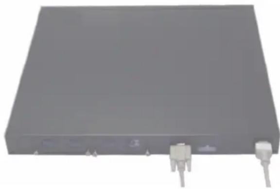
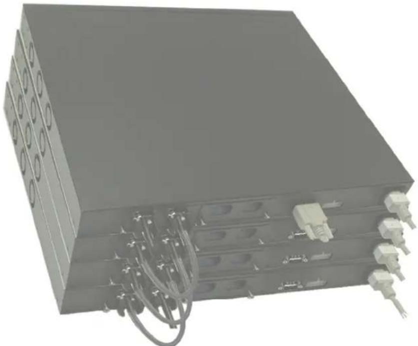
1-3xynxynn

y
nnn nn nynny
nno nnpn no npnn n nn nnn nnn nnn nnn nnn
wnn7nnn nnnn nn nnnn
n nn Dell 7y nnnn nn nn nn nn nn nn nn nn nn nn nn nn nn nn nn nn nn nn nn nn nn nn nn nn nn nn nn nn nn nn nn nn nn nn nn nn nn nn nn nn nn nn nn nn nn nn nn nn nn nn nn nn nn nn nn nn nn nn nn nn nn nn nn nn nn nn
.support.dell.com
. support.dell.com nnd Dell w noann nnneennn nee annnnn nn anan an anan

nnn nn
n nn nnnn nn nnnn nn nnnn nn nnnn nn nnnn nn nnnn nn nnnn nn nnnn nn nnnn nn nnnn nn nnnn nn nnnn nn nnnn nn nnnn nn nnnn nn nnnn nn nnnn nn nnnn nn nnnn nn nnnn nn nnnn nn nnnn nn nnnn nn nnnn nn nnnn nn nannn nn nannn nn nannn nn nannn nn nannn nn nannn nn nannn nn nannn nn nannn nn nannn nn nannn nn nannn nn nannn nn nannn nn nannn nn nannn nn nannn nn nannn nn nannn nn nannn nn nannn nn nannn nn
.Data Terminal Equipment (DTE)
:
nnnn nnnn nn nnnn nn nnnn nn nnnn nn nnnn nn nnnn nn nnnn nn nnnn nn nnnn nn nnnn nn nnnn nn nnnn nn nnnn nn nnnn nn nnnn nn nnnn nn nnnn nn nnnn nn nnnn nn nnnn nn nnnn nn nnnn nn nnnn nn nnnn nn nnnn nn nnnn
.VT100
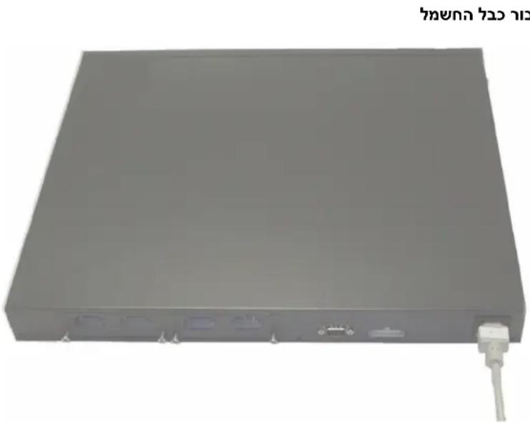
1.2
y
576-1000, 12 PowerConnect 6200 n
nyny

nnnn nn nnnn nn nnnn nnnn nnnn nnnn nnnn nnnn nnnn nnnn nnnn nnnn nnnn nnnn nnnn nnnn nnnn nnnn nnnn nnnn nnnn nnnn nnnn nnnn nnnn nnnn nnnn nnnn nnnn nnnn nnnn nnnn nnnn nnnn nnnn nnnn
1
2
3
4
Kny ann nnn
yynn

an anan anan npwn nnw nwnn nn nnnn nn
nss npnn nnn nn no pno
1
13-5 2
tionnn
nTn nnn nn nee nee nee nee nee nee nee nee nee nee nee nee nee nee nee nee nee nee nee nee nee nee nee nee nee nee nee nee nee nee nee nee nee nee nee nee nee nee nee nee nee nee nee nee nee nee nee nee nee nee neee
.VT100 7
2
y
CL-wnnnn nn,wnnnn qnnn nn nnnn nn nnnn nn
nn 7907 nn n
nnn nn n nn nn nn nn nn nn nn nn nn nn nn nn nn nn nn nn nn nn nn nn nn nn nn nn nn nn nn nn nn nn nn nn nn nn nn nn nn nn nn nn nn nn nn nn nn nn nn nn nn nn nn nn nn nn nn nn nn nn nn nn nn nn nn nn nn nn nn nn nn nn nn nn nn nn nn nn nn nn nn nn nn nn nn nn nn nn nn
.
1
(wn) PowerConnect RPS-600 12 VDC nn nnnn pps 2
DCbwnnPoEPnB EPS-470 PowerConnect ,PoE
yyn" yoyooohnnn nn nnnnnnnnnnnnnnnnnnnnnnnnnnn
"ann nn nnnn
n nn nnnn
y 1
nnpn np nwnn nn nnnn nn nnnn nn
nnpnn nnn nn nnn 2
3
4
5

annn
nnn nn nnnn nn nnnn nn nnnn nn nnnn nn nnnn nn nnnn
.100000000000000000000000000000000000000000
PowerConnect nnnn nn nnnn nnnn nnnn nnnn nnnn DC-AC nannnnnn
PoE EPS-470 PowerConnect ,PoE RPS-600
Tayna nTin npnn
n nnnnnnnnnnnnnnnnnnnnnnnnnnnnnnnnnnnnnnnnnnn
n nn nnnn npn nn nn nnnn nn nn nn nn nn nn nn
.
nynnnnnnnnnnnnnn nn, nnnnnnnnnnnnnnnnnnnnn
nnn nn nnnn nn nnnn nn nnnn nn nnnn nn nnnn
n 1-1 n npnn
1.1
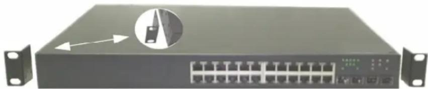
n nn nnnnnnnnnnnnnnnnnnnnnnnnnnnnnnnnnnnnnnnnnnnnnnnnnnnnnnnnnnnnnnnnnnnnnnnnnnnnnnnnnnnnnnnnnnnnnnnnnnnnnnnnn
3
4
()
nnnnn nn nnnn nn nnnn
.0101010101010101010101010101010101010101010101010101010101010101010101010101010
Tnynnnn nn nnnn nnnnnnnnnnnnnnnnnnnnnnnnnnnnnnnnnnnnnnnnnnnnnnnnnnnnnnnnnnnnnnnnnnnnnnnnnnn

1


#
,PC6224 ,DellTM PowerConnectTM nwnn nn nnnn npnp npnnn pnnn nnnn nnnn nnnn nnnn nnnn nnnn nnnn nnnn nnnn nnnn nnnn nnnn nnnn nnnn nnnn nnnn nnnn nnnn nnnn nnnn nnnn nnnn nnnn nnnn nnnn nnnn nnnn nnnn nnnn nnnn nnnn nnnn nnnn nannn nannn nannn nannn nannn nannn nannn nannn nannn nannn nannn nannn nannn nannn nannn nannn nannn nannn nannn nannn nannn nannn nannn nannn nannn nannn nannn nannn nannn nannn nannn nannn nannn
#
(1) nwnn nn nnnn 18, 48.26 6200 nnnn nn nnnn nn nnnn nn nnnn nn nnnn nn nnnn nn nnnn nn nnnn nn nnnn nn nnnn nn nnnn nn nnnn nn nnnn nn nnnn nn nnnn nn nnnn nn nnnn nn nnnn nn nnnn nn nnnn nn nnnn nn nnnn nn nnnn nn nnnn nn nnnn nn nnnn
100-250 VAC, 50-60 Hz hwn npn -
nww nwn nn wnn nnn nnn nnn nnn nnn nnn
nannnnnn
n nnnn nn nnnn nnnn nnnn nnnn nnnn nnnn nnnn nnnn nnnn nnnn nnnn nnnn nnnn nnnn nnnn nnnn nnnn nnnn nnnn nnnn nnnn nnnn nnnn nnnn nnnn nnnn nnnn nnnn nnnn nnnn nnnn nnnn nnnn nnnn
.0000000000
95 1000045°C-00000000000000000000000000000
y 1
nnnnnnnn
nnnnn
:
tnk PowerConnect and
TNN
RS-232
()
(1)
wnnnn nn nnnn
77327777777
7777
- nyny
275
275
275
275
275
275
276 0nn/Telnet/CLI
276.
276.
276
276 1nnn
LED nnnn nn n 4
277
277 LED
279. LED
280 RJ-45 LEDs (PoE)
280 XFP LED
280 SFP LED
in
- nnn
265
265
265
266
266
266
267
267
267 1nnn nn n
268
ann nn nnnn nn nnnn .2
269
271
271
271
272
nyn,niinai niy
nni nnnn nn nnnn nn nnnn nn nnnn

yTIN

ninn nnnn nn nnnnnn nn nnnn

nntn nnnn nn nnnn nnnn nnnn
. Dell Inc. 2007 ©
Dell Inc. 1
Microsoft Dell Inc. PowerConnect- Dell, Dell
Microsoft Corporation 7
an anan anan anan anan anan anan anan anan anan anan anan anan anan anan anan anan anan anan anan anan anan anan anan anan anan anan anan anan anan anan anan anan anan anan anan anan anan anan anan anan anan
nss nnnnnnnnnnnnnnnnnnnnnnnnnnnnnnnnnnnnnnnnnnnnnnnnnnnnnnnnnnnnnnnnnnnnnnnnnnnnnnnnnnnnnnnnnnnnnnnnnnnnnnnnnnnnnnnnnnnnnnnnnnnnn
PC6224F-1 PC6248P,PC6224P,PC6248,PC6224n
A02 P/N YC897 2007
ton nn
Dell™ PowerConnect™ 6200
Tnnnnn
PC6224F-1 PC6248P,PC6224P,PC6248,PC6224 n'nt
www.dell.com | support.dell.com

- Series Stackable Switches
- Getting Started Guide
- Notes, Notices, and Cautions
- Contents
- Installation
- Starting and Configuring the Switch
- Managing a Stack
- Front Panels and LEDs
- Installation
- Site Preparation
- Unpacking the Switch
- Package Contents
- Unpacking Steps
- Mounting the Switch
- Installing in a Rack
- Installing as a Free-standing Switch
- Connecting a Switch to a Terminal
- Connecting a Switch to a Power Supply
- Assembling a Stack
- Starting and Configuring the Switch
- Connecting the Terminal to the Switch
- Booting the Switch
- Initial Configuration
- Initial Configuration Procedure
- Example Session
- Step 1:
- Step 2:
- Step 3:
- Step 4:
- Step 5:
- Managing a Stack
- Master and Member Switches
- Stack Startup
- Topology Discovery
- Auto Stack ID Assignment
- Firmware Version Checking
- System Initialization
- System Initialization for Normal Stacking Mode
- System Initialization for Suspended Stacking Mode
- CLI/Telnet/Web Interface
- Insertion and Removal of Switches
- Operating as Standalone Switch
- Stack ID Renumbering
- User Controls
- Front Panels and LEDs
- Front Panels
- LEDs
- Systems LEDs
- RJ-45 LEDs (PoE)
- XFP LED
- SFP LED
- Dell™ PowerConnect™
- 6200系列可堆叠交换机
- 使用入门指南
- 注、注意和警告
- 前面板和LED
- Postup rozbalen
- Krok 1:
- Krok 2:
- Krok 4:
- Krok 5:
- Správa stohu
- Etape1:
- Étape 2:
- Étape 4:
- Étape 5:
- Gestion d'une pile
- Schritt 1:
- Schritt 2:
- Schritt 4:
- Schmitt 5:
- Bnμα1:
- Bnμα2:
- Bnμα 4:
- Bnμα 5:
- Δiaxεiρiσn σtoiβας
- 手順1:
- 手順2:
- -Stuckの管理
- マスロースイチとメンバームスイチ
- 前面八徳ルとLED
- 1.
- 2.1.1:
- 4.
- 5.1
- Stacking
- ☆sTeJfJgHJFJ
- 朝元 广南 笼 LED
- 朝通
- Zarzbazanie wieża
- Diody LED RJ-45 (PoE)
- Paso 1:
- Paso 2:
- Paso 4:
- Paso 5:
- Adm 1:
- Adm 2:
- Adm 4:
- Adm 5:
- nTTnHLED
- DNT7NINH
- yannnnn nnnn
- nyin nynn nnynnn
- wnn/Telnet/CLI
- ann nn noon noon
- Xnxyannn
- nnynn nn ywnn nison
- Dunnun T79
- nny
- DUNI DUNT DNN
- 1:
- w2:
- nniy
- ann nnx yix
- nnnnnnnny
- nnnnn nnnnny
- nnn nn nynny
- nnn nn
- y
- tionnn
- nn 7907 nn n
- n nn nnnn
- annn
- Tayna nTin npnn
- #
- nnnnnnnn
- nnnnn
- in
Brand : DELL
Model : PowerConnect 6248P
Category : Router