
Edge 3800 - Router DELL - Free user manual and instructions
Find the device manual for free Edge 3800 DELL in PDF.


| Product Type | SD-WAN Edge Router |
| Brand | Dell |
| Model | Edge 3800 (16-core) |
| Dimensions (W x D x H) | 17.1 x 15 x 1.72 in (43.4 x 38.1 x 4.37 cm) |
| Weight | 16.50 lb (7.48 kg) with 2 PSUs and 5 fans |
| Power Supply | 2 x hot-swappable AC PSUs, 100-240 VAC, 50/60 Hz |
| Typical Power Consumption | 208 W |
| Maximum Power Consumption | 312 W |
| Input Current (Typical) | 1.89 A at 110 VAC, 0.87 A at 240 VAC |
| Network Interfaces | 4 x 10GbE SFP+, 6 x 1GbE copper, 2 x 10/100/1000Base-T management ports (CPU and BMC) |
| Console Ports | 1 x RS-232 RJ-45 (CPU), 1 x RS-232 RJ-45 (BMC), 1 x MicroUSB-B |
| USB Ports | 2 x USB Type-A 3.0 |
| Storage | 1 x M.2 240 GB SATA SSD |
| Memory | 4 x 8 GB DDR4 DIMMs, total 32 GB |
| Cooling | 5 x hot-swappable fans (airflow from I/O to PSU side) |
| Pre-installed Software | VMware SD-WAN by VeloCloud |
| Operating Temperature | 0°C to 45°C (32°F to 113°F) |
| Operating Humidity | 5% to 85% non-condensing (continuous), up to 90% short term |
| Rack Mounting | 1U, 19-inch rack, two-post or four-post (four-post kit sold separately) |
| Safety Compliance | UL 60950-1, CSA 60950-1, EN 60950-1, IEC 62368-1, FCC Class A, CE, VCCI Class A |
| Maintenance | Check fans every 6 months; replace PSU or fan modules as needed; use ESD precautions; clean with dry cloth |
| Repairability | Field-replaceable units: PSUs and fan modules only; no user-serviceable internal parts; contact Dell for service |
Frequently Asked Questions - Edge 3800 DELL
User questions about Edge 3800 DELL
0 question about this device. Answer the ones you know or ask your own.
Ask a new question about this device
Download the instructions for your Router in PDF format for free! Find your manual Edge 3800 - DELL and take your electronic device back in hand. On this page are published all the documents necessary for the use of your device. Edge 3800 by DELL.
USER MANUAL Edge 3800 DELL
Dell EMC SD-WAN Edge 3000 Series Installation Guide
August 2019
Notes, cautions, and warnings
NOTE: A NOTE indicates important information that helps you make better use of your product.
CAUTION: A CAUTION indicates either potential damage to hardware or loss of data and tells you how to avoid the problem.
WARNING: A WARNING indicates a potential for property damage, personal injury, or death.
Contents
1 About this guide....5
Related documents....5
Information symbols....5
Physical dimensions....8
LEDs....8
Prerequisites....10
Luggage tag....10
3 Site preparations....12
Site selection....12
Cabinet placement....12
Rack mounting....12
Platform ground....12
Fans and airflow....13
Power....13
Storing components....13
4 Edge 3000 Series installation....14
Unpack....14
Ground lug....14
Rack or cabinet hardware installation....15
Two-post installation....16
1U front-rack installation.... 16
Four-post installation....17
Optics installation....18
Optics removal....18
Platform power-up....18
5 Platform setup....20
6 Power supplies....22
Components....22
AC power supply installation....22
AC power supply replacement....23
7 Fans....24
Components....24
Fan module installation....24
Fan module replacement....25
8 Management ports....26
RS-232 console port access....26
MicroUSB-B console port access....26
9 User interface....28
Overview....28
Properties....29
Reset settings....30
10 Specifications.... 31
Chassis physical design....31
IEEE standards....32
Agency compliance....32
USA Federal Communications Commission statement.... 32
European Union EMC directive conformance statement.... 33
Japan VCCI compliance for class A equipment....33
Korean certification of compliance....34
Safety standards and compliance agency certifications....34
Product recycling and disposal....35
11 Dell EMC support.... 36
About this guide
This guide provides site preparation recommendations, step-by-step procedures for rack mounting and desk mounting your platform, and connecting to a power source.
CAUTION: To avoid electrostatic discharge (ESD) damage, wear grounding wrist straps when handling this equipment.
NOTE: Only trained and qualified personnel can install this equipment. Read this guide before you install and power up this equipment. This equipment contains two power cables. Disconnect both power cables before servicing.
NOTE: This equipment contains optical transceivers, which comply with the limits of Class 1 laser radiation.
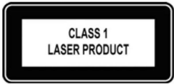
Figure 1. Class 1 laser product tag
NOTE: When no cable is connected, visible and invisible laser radiation may emit from the aperture of the optical transceiver ports. Avoid exposure to laser radiation. Do not stare into open apertures.
NOTE: Read this guide before unpacking the platform. For unpacking instructions, see Unpack.
Regulatory
Marketing model Edge 3400 and 3800 platform is represented by the regulatory model E25W and the regulatory type E25W001.
Topics:
- Related documents
• Information symbols
Related documents
For more information about the Dell EMC SD-WAN Edge 3000 Series (3400 and 3800) platform, see the following documents:
• VeloCloud User Guide
• Dell EMC SD-WAN Edge 3000 Series Quick Start Guide
• Dell EMC SD-WAN Edge 3000 Release Notes
NOTE: To access product documentation, see Dell EMC support: www.dell.com/support.
Information symbols
This book uses the following information symbols:
NOTE: The Note icon signals important operational information.
CAUTION: The Caution icon signals information about situations that could result in equipment damage or loss of data.
NOTE: The Warning icon signals information about hardware handling that could result in injury.
NOTE: The ESD Warning icon requires that you take electrostatic precautions when handling the device.
Edge 3000 Series
The following sections describe the Dell EMC SD-WAN Edge 3000 Series (3400 and 3800):
- Dell EMC SD-WAN Edge—a hardware device with VeloCloud/VMware software preinstalled.
- VeloCloud/VMware Gateway—a virtual machine that is hosted on the Internet with the VeloCloud/VMware software preinstalled. VeloCloud/VMware manages the Gateway.
- VeloCloud/VMware Orchestrator—a graphic user interface (GUI) hosted on the Internet and used to configure the preinstalled VeloCloud/VMware software. Your network administrator configures the Orchestrator. VeloCloud/VMware manages the Orchestrator.
NOTE: For software information, see VeloCloud, now part of VMware, documentation at www.velocloud.com.
Topics:
- Introduction
- Features
• Physical dimensions
• LEDs
- Prerequisites
• Luggage tag
Introduction
The one rack-unit (1RU) SD-WAN Edge 3000 Series (3400 and 3800) is a Dell EMC purpose-built platform complete with VeloCloud software. The high-performance platform hosts VMware SD-WAN software and is meant for the service provider edge or enterprise branch.
The platform includes two 10/100/1000Base-T management ports—one for the central processing unit (CPU) and one for the baseboard management controller (BMC). It also includes two Type-A USB ports that support USB 3.0 and one MicroUSB Type-B console port.
The Edge 3000 Series supports 1- and 10-Gbps speeds.

- USB Type-A and MicroUSB Type-B ports
- BMC and CPU management ports and console ports
- 10 GbE SFP+ ports—SFP3 and SFP4 WAN connections
- SD-WAN ports—default GE5 and GE6 WAN connections
- 10 GbE SFP+ ports
6.1 GbE copper ports—default GE1 and GE2 LAN connections - 1 GbE copper ports—same function as GE5 and GE6 WAN connections
The Edge 3000 Series includes two hot-swappable AC power supplies and four or five hot-swappable fans.
• 16 core: two AC PSUs and five fans
• 8 core: two AC PSUs and four fans

-
PSUs
-
Fans
Features
• 16 core: Dell EMC SD-WAN Edge 3800
• 8 core: Dell EMC SD-WAN Edge 3400
• Four 10 GbE SFP+ ports
- Six 1 GbE ports
- One 10/100/1000Base-T port for the CPU
• One 10/100/1000Base-T port for the BMC
• One console port for the CPU
• One console port for the BMC
- Two USB Type-A USB 3.0
• One MicroUSB Type-B for console port
• One M.2 240 GB SATA SSD
• BMC IPMI 2.0 compliant
• Four 8 GB DDR-4 DIMMs for a total of 32 GB
- Two hot-swappable AC PSUs
- 16 core: five hot-swappable fans with airflow from the I/O-side to the PSU-side of the platform
- 8 core: four hot-swappable fans with airflow from the I/O-side to the PSU-side of the platform
- VMware SD-WAN software pre-loaded
Physical dimensions
- 17.1 in x 15 in x 1.72 in (W x D x H)
· 43.4 cm × 38.1 cm × 4.37 cm (W × D × H)
LEDs
The Edge 3000 Series platform includes LED displays on the I/O side of the platform.

-
Master LED
-
System LED
-
Locator LED
-
Power LED
-
Fan LED
-
Temperature LED
-
BMC and CPU console and management port LEDs
-
rNDC system and temperature LEDs
-
10 GbE SFP+ port LEDs—SFP3 and SFP4
-
SD-WAN port LEDs—GE5 and GE6
-
10 GbE SFP+ port LEDs
-
1 GbE copper port LEDs—same function as GE1 and GE2
-
1 GbE copper port LEDs—same function as GE5 and GE6
Table 1. Edge 3000 Series LED behavior
LED Description
| Master LED | Solid green—platform is in stacking Master or Stand alone modeOff - system is slave of the stack or system in standby |
LED Description
| System LED | ·Off - system off or in standby·Solid green—Normal operation·Flashing green—Booting·Solid yellow (amber)—Critical system error or CPU power off.·Flashing yellow—Noncritical system error, fan failure, or power supply failure |
| Locator LED | ·Off—Locator function disabled·Flashing blue with 1 sec on and 1 sec off – Locator function enabled·Flashing blue with 2 sec on and 1 sec off – system in standby |
| Power LED | ·Off - system off or in standby·Solid Green—Normal operation·Solid yellow—POST is in process·Flashing yellow—Power supply failed |
| Fan LED | ·Off - system off or in standby·Solid green—Normal operation; fan powered and running at the expected RPM·Solid yellow—Fan failed |
| Temperature LED | ·Off - system off or in standby·Solid green—temperature is normal·Solid yellow—temperature is at the limit·Flashing yellow—temperature is over the limit |
| rNDC - System LED | ·Off - system off or in standby·Solid green—Normal operation·Flashing green—Booting·Solid yellow (amber)—Critical system error·Flashing yellow—Noncritical system error |
| rNDC - Temperature LED | ·Off - system off or in standby·Solid green—temperature is normal·Solid yellow—temperature is at the limit·Flashing yellow—temperature is over the limit |
| 10 GbE SFP+ port LEDs | ·Off—No link·Solid green—Link operating at maximum speed, 10G·Solid yellow—Link operation and activity at a lower speed, 1G·Flashing green—port activity for 10G |
| SD-WAN port LEDs—GE5 and GE6 | ·Off—No link·Solid green—Link operating at maximum speed, 10G·Solid yellow—Link operating at a lower speed, 1G·Flashing green—port activity for 10G·Flashing yellow—port activity for 1G |
| 1 GbE copper port LEDs—same function as GE5 and GE6 | ·Off—No link·Solid green—Link operating at maximum speed, 10G·Solid yellow—Link operating at a lower speed, 1G·Flashing green—port activity for 10G·Flashing yellow—port activity for 1G |
LED Description
| 10 GbE SFP+ port LEDs—SFP3 and SFP4 | · Off—No link · Solid green—Link operating at maximum speed, 10G · Solid yellow—Link operating at a lower speed, 1G · Flashing green—port activity for 10G · Flashing yellow—port activity for 1G |
Table 2. BMC and CPU Console and management Ethernet port LEDs
LED Description
| Link LED | · Off—No link · Solid green—Link operating at a maximum speed, autonegotiated/forced or 1G · Solid yellow—Link operating at a lower speed, autonegotiated/ forced or 10/100M |
| Activity LED | · Off—No link · Flashing green—Port activity |
Prerequisites
For installation instructions, see Site preparations and Edge 3000 Series installation.
The following is a list of components need to install the Edge 3000 Series platform:
• Dell EMC SD-WAN Edge 3400 or 3800 platform
- AC country- and regional-specific cables
- Two-post rail kit mounting brackets for rack installation, included
- Screws for rack installation
• #1 and #2 Phillips screwdrivers, not included
• M2 Philips drive flat head screwdriver, not included
- Ground cable screws for L-bracket—order separately
- M3 ground lug assembly kit screw
• Copper/fiber cables
Other optional components are:
- Expansion card
- UL-certified ground lug assembly kit with bracket
- Extra mounting brackets for the four-post mount
Luggage tag
The Edge 3000 Series has a pull-out tag, known as a luggage tag, on the I/O-side of the platform. The front of the luggage tag includes platform ID information.
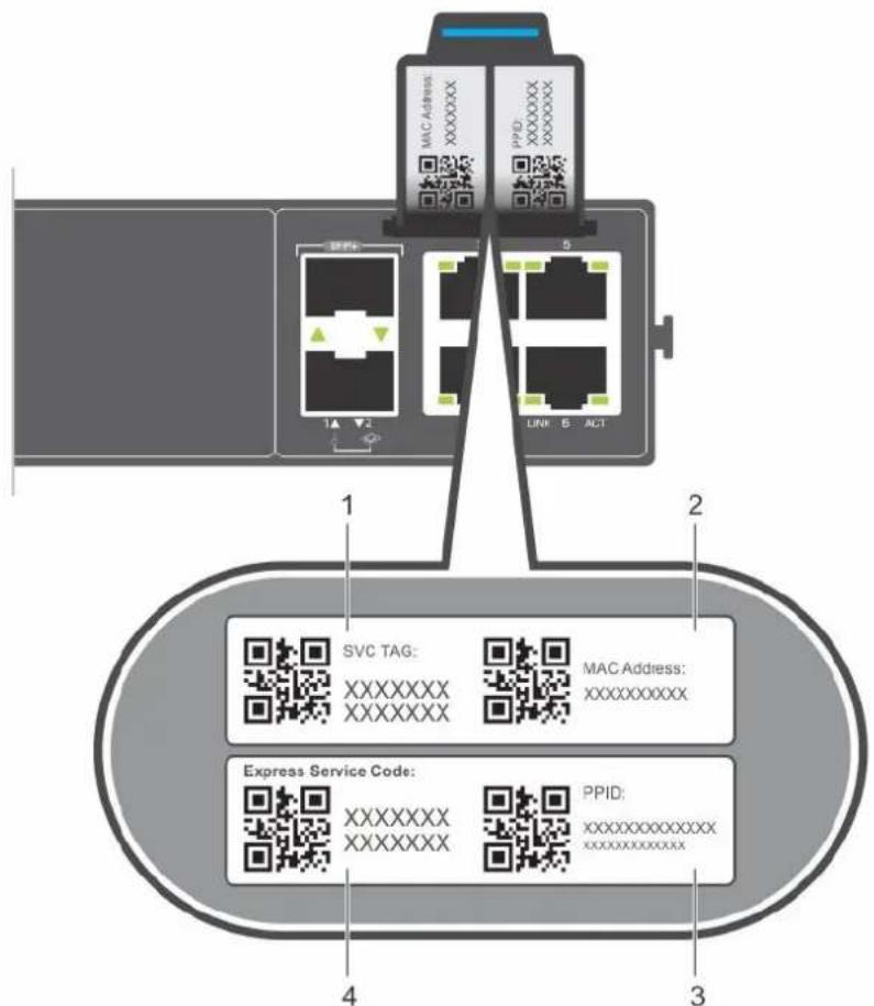
- SVC tag
- MAC address
- PPID
- Express service code
Site preparations
The Edge 3000 Series platform is suitable for installation as part of a service provider edge or enterprise branch.
NOTE: Install the platform into a rack or cabinet before installing the components.
Topics:
- Site selection
- Cabinet placement
- Rack mounting
- Platform ground
- Fans and airflow
• Power - Storing components
Site selection
Install the platform equipment in restricted access areas.
A restricted access area is one in which service personnel can only gain access using a special tool, lock, key or other means of security. The authority responsible for the location controls access to the restricted area.
Ensure that the area where you install your platform meets the following safety requirements:
- Near an adequate power source. Connect the platform to the appropriate branch circuit protection according to your local electrical codes.
- Platform environmental temperature range is from 0^ to 45^ (32° to 113°F).
- Relative humidity is from 5 to 90 percent noncondensing.
• In a dry, clean, well-ventilated, and temperature-controlled room, away from heat sources such as hot air vents or direct sunlight - Away from sources of severe electromagnetic noise
- Inside the restricted access area that is positioned in a rack or cabinet, or on a desktop with adequate space in the front, back, and sides for proper ventilation and access
• Install the platform in Information Technology Rooms in accordance with Article 645 of the National Electrical Code and NFPA 75.
For more information about platform storage and environmental temperatures, see Specifications.
Cabinet placement
Install the Edge 3000 Series only in indoor cabinets that are designed for use in a controlled environment.
Do not install the platform in outside cabinets. For cabinet placement requirements, see Site selection.
The cabinet must meet minimum size requirements. Airflow must be in accordance with the Electronic Industries Alliance (EIA) standard. Ensure that there is a minimum of 5 inches (12.7 cm) between the intake and exhaust vents and the cabinet wall.
Rack mounting
When you prepare your equipment rack, ensure that the rack is grounded.
Ground the equipment rack to the same ground point the power service in your area uses. The ground path must be permanent.
Platform ground
Dell EMC recommends you ground your platform.
Connect the grounding cables as described in Edge 3000 Series installation.
NOTE: For an AC-powered platform although the third conductor of the AC power cord provides a ground path, Dell EMC recommends grounding your platform with a dedicated ground wire.
Fans and airflow
Fan installation is done as part of the factory. The Edge 3000 Series supports two AC PSUs with fan airflow from the I/O to the PSU.
For proper ventilation, position the platform in an equipment rack or cabinet with a minimum of 5 inches (12.7 cm) of clearance around the exhaust vents. When you install two Edge 3000 Series platforms near each other, to permit proper airflow, position the two platforms at least 5 inches (12.7 cm) apart. The fan speed varies based on internal temperature monitoring. The Edge 3000 Series never intentionally turns off the fans.
For more information, see Fans.
Power
Connect the platform to the appropriate power source using the appropriate power cable. An AC power cable is included with each PSU.
When installing AC platforms, follow the requirements of the National Electrical Code, ANSI/NFPA 70, where applicable.
The platform is powered-up when you connect the power cable between the platform and the power source. For more information, see Power supplies.
CAUTION: Always disconnect the power cable before you service the power supply slots. The platform has multiple power cables. Before servicing, ensure that all power cables are disconnected.
CAUTION: Use the AC power supply cord as the main disconnect device. Ensure that the socket-outlet is located and installed near the equipment and is easily accessible.
Processor power button
The processor power button is on the I/O-side of the platform.
- To turn on the processor, hold the button down for one second.
- To turn off the processor, hold the button down for five seconds.
CAUTION: Always turn off the processor correctly. For the processor to boot correctly after you have turned off the platform, hold the processor power button down for five seconds.
NOTE: Before you unplug the platform power cable, either turn off the processor using the software console or hold the processor power button down for five seconds.
Storing components
If you do not install your Edge 3000 Series platform and components immediately, properly store the platform and all components using these guidelines:
- Storage location temperature must remain constant. The storage range is from -40^ to 70^ (-40° to 158°F).
- Store on a dry surface or floor, away from direct sunlight, heat, and air conditioning ducts.
- Store in a dust-free environment.
NOTE: ESD damage can occur when components are mishandled. Always wear an ESD-preventive wrist or heel ground strap when handling the platform and accessories. After you remove the original packaging, place the platform and components on an anti-static surface.
Edge 3000 Series installation
To install the Edge 3000 Series platform, complete the installation procedures in the order that is presented in this chapter.
Always handle the platform and components with care. Avoid dropping the platform or its field replaceable units (FRUs).
NOTE: ESD damage can occur if components are mishandled. Always wear an ESD-preventive wrist or heel ground strap when handling the platform and components. As with all electrical devices of this type, take all the necessary safety precautions to prevent injury when installing this platform.
Topics:
- Unpack
- Ground lug
- Rack or cabinet hardware installation
- Two-post installation
- Four-post installation
- Optics installation
- Platform power-up
Unpack
NOTE: Before unpacking the platform, inspect the container and immediately report any evidence of damage.
When unpacking the platform, ensure that the following items are included:
• One Edge 3000 Series platform
• One RJ-45 to DB-9 female cable
- Two-post rail kit; no tools required
• One or two country- or region-specific AC power cables, depending on the configuration
• Dell EMC SD-WAN Edge 3000 Series Quick Start Guide
• Safety and Regulatory Information
• Warranty and Support Information
- Place the container on a clean, flat surface and cut all straps securing the container.
- Open the container or remove the container top.
- Carefully remove the platform from the container and place it on a secure and clean surface.
- Remove all packing material.
- Inspect the product and accessories for damage.
Ground lug
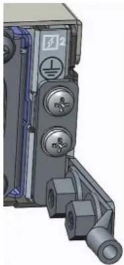
Dell EMC recommends you ground your Edge 3000 Series platform; however, grounding is optional and the ground lug assembly kit is not included with the platform. The ground lug must be a UL-recognized, crimp-type lug. To order a UL-certified ground lug with bracket, contact your Dell EMC sales representative.
NOTE: The ground cable and lug are not included with the platform.
NOTE: For AC-powered platform although the third conductor of the AC power cable provides a ground path, Dell EMC recommends grounding your platform with a dedicated ground wire.
To attach a ground lug assembly to the platform, use the included two M3 ground lug bracket screws. The platform ships with the M3 ground lug bracket screws attached.
CAUTION: Grounding conductors must be made of copper. Do not use aluminum conductors.
NOTE: Coat the one-hole lug with an antioxidant compound before crimping. Also, bring any unplated mating surfaces to a clean finish and coat with an antioxidant before mating. Plated mating surfaces must be clean and free from contamination.
NOTE: The rack installation ears are not suitable for grounding.
Before you install the platform:
-
Cut the user-supplied ground cable to the wanted length. The cable length must facilitate proper operation of the fault interrupt circuits. Use the shortest cable route allowable.
-
Attach the user-supplied ground lug using M3 screws.
Order a UL-certified GND lug with bracket separately.
natural_image
3D mechanical component with mounting holes and a cylindrical shaft (no visible text or symbols)- Attach the other end of the ground cable to a suitable ground point such as the rack or cabinet.
Rack or cabinet hardware installation
You may either place the platform on a rack shelf or mount the application directly into a 19" wide, EIA-310-E-compliant rack.
The platform includes two-post rail assemblies.
WARNING: This document is a condensed reference. Read the safety instructions in your Safety, Environmental, and Regulatory information booklet before you begin.
NOTE: The figures in this document are not intended to represent a specific platform.
NOTE: Do not the use the mounted two-post rails as a shelf or a workplace.
Rack mount safety considerations
- Rack loading—Overloading or uneven loading of racks may result in shelf or rack failure, possibly damaging the equipment and causing personal injury. Stabilize racks in a permanent location before loading begins. Mount the components starting at the bottom of the rack, and then work to the top. Do not exceed your load rating of the rack.
- Power considerations—Connect only to the power source specified on the unit. When you install multiple electrical components in a rack, ensure that the total component power ratings do not exceed the circuit capabilities. Overloaded power sources and extension cords present fire and shock hazards.
- Elevated ambient temperature—If installed in a closed rack assembly, the operating temperature of the rack environment may be greater than the room ambient temperature. Use care not to exceed the 45^ maximum ambient temperature of the platform.
- Reduced air flow—Install the equipment in the rack so that the amount of airflow that is required for safe operation of the equipment is not compromised.
- Reliable earthing—Maintain reliable earthing of rack-mounted equipment. Pay particular attention to the supply connections other than the direct connections to the branch circuit, for example, use of power strips.
- Do not mount the equipment with the back panel facing downward.
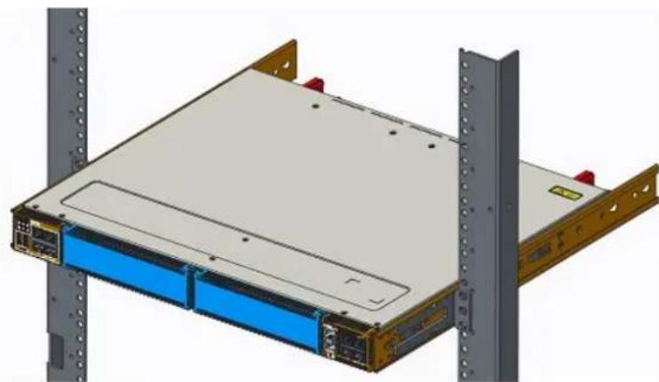
Two-post installation
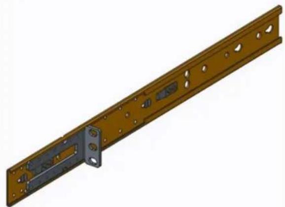
To configure your rack for installation, use the two-post rack mounting system that is provided. To complete this installation, supply four rack-mounting screws.
To begin installation, separate each rail assembly by sliding the inside rail out of the outside rail.
NOTE: For more installation instructions, see the installation labels attached to the rail assembly.
natural_image
3D rendering of a metal bracket with mounting holes and internal components (no text or symbols)1U front-rack installation
- Attach the inner platform rails to the Edge 3000 Series platform.
Line up the half-holes on the rail with the mounting heads on the platform and attach the rail to the platform. Slide the rail back until it locks into place.

natural_image
3D rendering of an electronic device chassis with blue and gray components, showing internal structure and mounting bracket (no text or symbols)- Repeat on the other side of the platform.
- Attach the outer platform rails to the two-post rack rails using two user-supplied screws on each side.
- After you install both rails, line up the platform rails with the installed rack rails. Slide the platform in until it is flush with the front of rack.
Approximately three inches before you fully insert your platform, the rail locking feature engages to keep the platform from inadvertently sliding out and falling.
natural_image
3D rendering of a server rack with blue drive bays and metal racks, no visible text or symbolsNOTE: Do not the use the mounted rails as a shelf or a workplace.
To remove the platform, unscrew the rack-mounting screws and slide the platform forward.
Four-post installation
Installing the Edge 3000 platform in a four-post rack is optional. To use this procedure, you must purchase the four-post rack mounting kit separately.
NOTE: For more installation instructions, see the installation labels attached to the rail assembly. To complete this installation, supply eight rack-mounting screws.
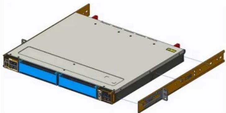
- Separate each rail assembly by sliding the inside rail out of the outside rail.
- Attach the inner platform rails to the Edge 3000 Series platform.
Line up the half-holes on the rail with the mounting heads on the platform and attach the rail to the platform. Slide the rail back until it locks into place.
natural_image
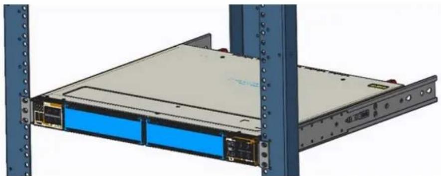
3D rendering of a server rack with blue and gold modules, showing front panel and side panel (no text or symbols)- Repeat on the other side of the platform.
- Attach the platform rails to the four-post rack rails using two user-supplied screws on each side.
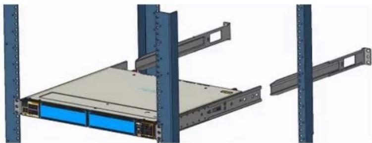
natural_image
3D rendering of a server rack with blue and black panels, mounted on a blue metal frame (no visible text or symbols)- Slide the rear platform rail from the back to the front bracket. Secure with two user-supplied screws on each side.
natural_image
3D rendering of a server rack with blue drive bays and metal racks, shown from two different angles (no text or symbols)Approximately three inches before you fully insert your platform, the rail locking feature engages to keep the platform from inadvertently sliding out and falling.
To remove the platform, unscrew the rack-mounting screws and slide the platform forward.
Optics installation
The Edge 3000 Series has SFP+ optical ports.
For a list of supported optics, see the specification sheets at https://www.dell.com/support or contact your Dell EMC Sales representative.

CAUTION: ESD damage can occur if components are mishandled. Always wear an ESD-preventive wrist or heel ground strap when handling the platform and components.

WARNING: When working with optical fibers, follow all warning labels and always wear eye protection. Never look directly into the end of a terminated or unterminated fiber or connector as it may cause eye damage.
- Position the optic to enter the port correctly.
The optic has a key that prevents it from being inserted incorrectly.
- Insert the optic into the port until it gently snaps into place.

NOTE: When you cable the ports, be sure not to interfere with the airflow from the small vent holes above and below the ports.
Optics removal
Remove an optic by pushing the tab on the optic and sliding the optic from the port.
When removing optics with direct attach cables (DACs) from the port, pull the release tab firmly and steadily. Before pulling the release tab, you may need to gently push the optic into the port to ensure that it is seated properly. Do not jerk or tug repeatedly on the tab.
Platform power-up
Supply power to the Edge 3000 Series after it is mounted in a rack or cabinet.
Dell EMC recommends reinspecting your platform before powering it up. Verify the following:
- Optional: The equipment is properly secured to the rack and properly grounded.
- Optional: The equipment rack is properly mounted and grounded.
- The ambient temperature around the unit, which may be higher than the room temperature, is within the limits that are specified for the platform. For more information, see the Specifications section.
- There is sufficient airflow around the unit.
- The input circuits are correctly sized for the loads and that you use sufficient overcurrent protection devices.
- All protective covers are in place.

CAUTION: Do not power up the platform if you did not install a fan module.

NOTE: A US AC power cable is included for powering up an AC power supply. You must order all other power cables separately.

NOTE: ESD damage can occur if components are mishandled. Always wear an ESD-preventive wrist or heel ground strap when handling the platform and components.
Power up sequence
When the platform powers up, the fans immediately come on at high speed. The fan speed slows as the platform continues to boot.
Platform setup

WARNING: To avoid electrostatic discharge (ESD) damage, wear grounding wrist straps when handling this equipment.
Install the device in an area that meets the following safety requirements:
- Near a properly grounded AC power outlet.
- In a temperature-controlled room with a continuous temperature range from 0^ to 40^ (32°F to 104°F).
- In a dry, clean, and well-ventilated room away from heat sources such as hot air vents or direct sunlight
- Away from severe electromagnetic noise
· Away from direct view within the workplace
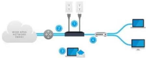
The numbers one through four in the following figure correspond to the setup procedure:
flowchart
graph LR
    A["Cloud"] --> B["Router"]
    B --> C["Switch"]
    C --> D["Computer 1"]
    C --> E["Computer 2"]
    C --> F["Computer 3"]
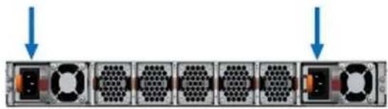
- Connect the power adapter to the AC power outlet. These power modules are 1+1 redundant power supplies.

NOTE: Connect the device to a properly wired earth-ground AC power outlet.
natural_image
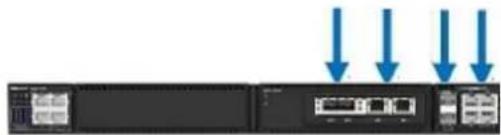
Diagram of server rack with multiple drive units and two arrows pointing to top (no text or symbols)- Connect one of the default WAN ports (GE3-6 or SFP1-4) to an available Internet connection. SFP modules are not included.
natural_image
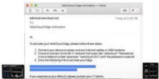
Front view of a server rack with four blue arrows pointing to a central control panel (no text or symbols visible)- If you received an email from your IT administrator, follow the instructions in the email to complete the Edge activation.
- Connect local devices such as computers and switches to the GE1 or GE2 ports.

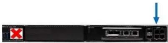
NOTE: The RJ45 ports on the left side of the box are for console/administration access only.
natural_image
Front view of a network device with a red X mark and blue downward arrow indicating a drop or error (no text or symbols present)After following these instructions, if you are still unable to activate the Edge, contact your Dell EMC sales representative.
Power supplies
The Edge 3000 Series ships with two AC power supplies, depending on the configuration. Airflow is from the I/O panel to the PSU.
Two PSUs are required for full redundancy, but the platform can operate with a single PSU.
The PSUs are field replaceable. When running with full redundancy—two power supplies installed and running—you can remove and replace one PSU without disrupting traffic.

CAUTION: To prevent electrical shock, ensure that the platform is grounded properly. If you do not ground your equipment correctly, excessive emissions may result. Use a qualified electrician to ensure that the power cables meet your local electrical requirements.

NOTE: Connect the power supply to the appropriate branch circuit protection as defined by your local electrical codes. Verify that the remote power source complies with the platform input power specifications.

NOTE: If you use a single PSU, install a blank plate in the other PSU slot. Use power supply 2 (PSU2) as the blank-plate slot. You do not need tools to install the blank plate.

NOTE: ESD damage can occur if components are mishandled. Always wear an ESD-preventive wrist or heel ground strap when handling the platform and components.
Topics:
- Components
• AC power supply installation
Components
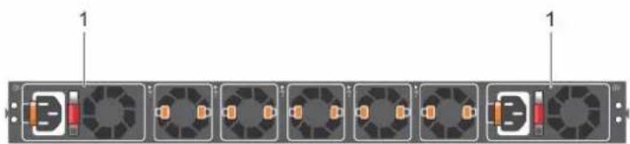
Both the 16- and 8-core platforms have two PSUs.
natural_image
Diagram of a rack-mounted server unit with multiple fans and indicator lights (no text or labels)1. PSUs
- Solid green—Input is OK.
- Flashing yellow (amber)—There is a fault with the PSU.
- Flashing green blink at 1 Hz—Platform is in a standby/CR state.
- Off—PSU is off.
AC power supply installation

NOTE: The PSU slides into the slot smoothly. Do not force a PSU into a slot as this action may damage the PSU or the platform.

NOTE: Ensure that you correctly install the PSU. When you install the PSU correctly, the power connector is on the left side of the PSU.
NOTE: If you use a single PSU, install a blank plate in the other PSU slot. If you are only using one power supply, install the power supply in the first slot, PSU1. Install a blank plate in the second slot, PSU2.
- Pull out the PSU slot cover.
- Remove the PSU from the electro-static bag.
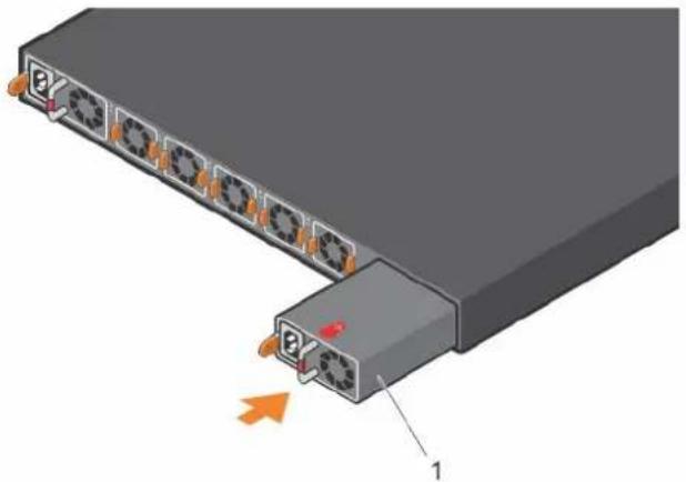
- Insert the PSU into the platform PSU slot—insert the exposed PSU connector first.
The PSU slot is keyed so that you can only fully insert the PSU in one orientation. When you install the PSU correctly, it snaps into place and is flushed with the back of the platform.
natural_image
3D diagram of a server rack with multiple ports and an orange arrow pointing to a terminal block (no text or symbols)a. 1—PSU installation
- Plug in the appropriate AC three-prongs cord from the platform PSU to the external power source.
- Repeat steps 1 through 4 if you have a redundant PSU using the second PSU slot.
NOTE: The platform powers up when you connect the cables between the power supply and the power source.
AC power supply replacement
CAUTION: Disconnect the power cable before removing the power supplies. Also, disconnect all power cable before servicing.
NOTE: The PSU slides into the slot smoothly. Do not force a PSU into a slot as this action may damage the PSU or the platform.
NOTE: If a PSU fails, you must replace the entire unit. There are no field serviceable components in the PSU. To request a hardware replacement, see https://www.dell.com/support.
NOTE: If you use a single PSU, install a blank plate in the other PSU slot. If you are only using one power supply, install the power supply in the first slot, PSU1. Install a blank plate in the second slot, PSU2.
- Disconnect the power cable from the PSU.
- Use the grab handle to slide the PSU out of the power supply bay.
- Use the grab handle on the replacement PSU to slide it into the power supply bay.
- Attach the power cable to the replacement PSU.
NOTE: The platform powers up when the cables are connected between the power supply and the power source.
The Edge 3000 Series platform ships from the factory with two PSUs and four or five AC normal fan modules that are installed in the platform, depending on the configuration. The fan modules and the power supplies, which have integrated fans, are hot-swappable.
Besides to the power supply modules, you can order and install fan modules separately.
The platform supports airflow is from the I/O panel to the PSU.
Environmental factors can decrease the amount of time required between fan replacements. Check the environmental factors regularly. An increase in temperature and/or particulate matter in the air might affect performance; for example, new equipment installation.

CAUTION: Check the fans at six-month intervals; replace them as necessary. Regularly monitor the speeds of the fans to accurately determine replacement intervals.
Topics:
- Components
- Fan module installation
Components
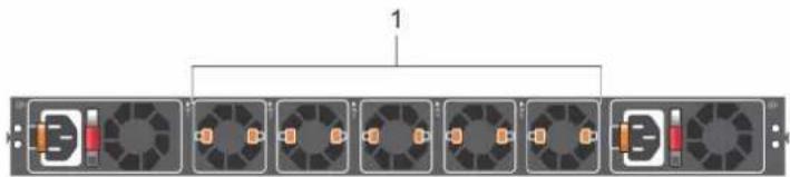
- 16 core: five fans
- 8 core: four fans
flowchart
graph TD
    A["Server Rack 1"] --> B["Central Rack Unit 1"]
    B --> C["Server Rack 2"]
    C --> D["Central Rack Unit 2"]
    D --> E["Server Rack 3"]
    E --> F["Central Rack Unit 3"]
    F --> G["Server Rack 4"]
    G --> H["Central Rack Unit 4"]
    H --> I["Server Rack 5"]
    I --> J["Central Rack Unit 5"]
    J --> K["Server Rack 6"]
    K --> L["Central Rack Unit 6"]
    L --> M["Server Rack 7"]
    M --> N["Central Rack Unit 7"]
    N --> O["Server Rack 8"]
1. Fans
Fan LEDs
- Solid green—Fan function is normal.
- Flashing yellow (amber)—There is a fan fault.
- Off—Fan is off.
Fan module installation
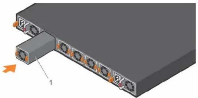
The fan modules in the Edge 3000 Series platform are field replaceable. Module slot 1 is on the left side of the platform; module slot 5 is on the right side of the platform.
- Take the fan module out of the shipping box.
- Slide the module into the bay.
natural_image
3D diagram of a server rack with multiple ports and an orange arrow indicating direction (no text or symbols)a. 1—Fan module installation
Fan module replacement
To request a hardware replacement, see https://www.dell.com/support.

CAUTION: Complete the following steps within one minute or the platform temperature could rise above safe thresholds and the platform could shut down:
- Slide the fan module out of the bay.
- Slide the replacement module into the bay.
Management ports
Besides the 10/100/1000Base-T RJ45 ports, the Edge 3000 Series platform provides several ports for management and storage.
NOTE: The output examples in this section are for reference only. Your output may vary.
Topics:
• RS-232 console port access
- MicroUSB-B console port access
RS-232 console port access
The RS-232 console port is on the I/O-side of the Edge 3000 Series.

natural_image
Back view of a network switch or server rack with ports and connectors (no visible text or labels)- RS-232: Processor console port (left); BMC console port (right)
CAUTION: Ensure that any equipment that is attached to the serial port can support the required 115200 baud rate.
NOTE: When connecting the RJ45 console to the patch panel or terminal server using Cat5e or Cat6 Ethernet cables, the maximum cable length is 100m. However, if the Ethernet cable is disconnected from the patch panel or terminal server but connected to the RJ45 console, the maximum cable length is 6m. If the cable is longer than 6m when disconnected from the panel or server, your platform may not boot.
NOTE: Before starting this procedure, ensure that your personal computer has a 9-pin serial port and that you have installed a terminal emulation program on the personal computer.
NOTE: If your personal computer serial port cannot accept a female DB-9 connector, use a DB-9 male-to-male adapter.
- Install the provided RJ45 connector-side of the provided cable into the platform console port.
- Install the DB-9 female-side of the provided copper cable into your personal computer serial port. Or install the DB-9 cable into other data terminal equipment (DTE) server hardware.
- Keep the default terminal settings on the console as follows:
• 115200 baud rate
- No parity
- 8 data bits
- 1 stop bit
- No flow control
MicroUSB-B console port access
The MicroUSB-B console port is on the I/O side of the Edge 3000 Series.
The terminal settings are the same for the serial console port and the RS-232/RJ-45 console port:
· 115200 baud rate
- No parity
- 8 data bits
- 1 stop bit
- No flow control
When you connect the microUSB-B port, it becomes the primary connection and, while connected, all messages are sent to the microUSB-B port.

NOTE: Before starting this procedure, ensure that you have a terminal emulation program already installed on your personal computer. Install the appropriate drivers to support the microUSB-B port. To download Dell EMC drivers, see https://www.dell.com/support. If your computer requires non-Dell EMC drivers, contact Dell EMC Technical Support for assistance.
- Power on the personal computer.
- Connect the USB-A end of cable into an available USB port on the personal computer.
- Connect the MicroUSB-B end of cable into the microUSB-B console port on the platform.
- Power on the platform.
- Install the necessary USB device drivers.
To download Dell EMC drivers, see https://www.dell.com/support. If your computer requires non-Dell EMC drivers, contact Dell EMC Technical Support for assistance.
- Open your terminal software emulation program to access the platform.
- Confirm that the terminal settings on your terminal software emulation program are as follows:
• 115200 baud rate
- No parity
- 8 data bits
- 1 stop bit
- No flow control
User interface
The Edge 3000 Series user interface (UI) includes local web pages—Overview, Properties, and Reset Settings—that provide troubleshooting functions and information about the interfaces.
Access the Edge 3000 Series UI at https://edge.velocloud.net, or at the IP address 192.168.2.1.
NOTE: Use the UI only for initial configuration and troubleshooting when the Internet is not available. Do not use the Edge 3000 Series UI during normal operations because the information and configurations are available using the VMware SD-WAN by VeloCloud Orchestrator. By default, LAN access to this interface is blocked after you activate your Edge 3000 Series platform.
Topics:
• Overview
- Properties
- Reset settings
Overview
The Overview page provides the status of the routed interfaces (WAN) and switched interfaces (LAN) connections.
The top half of the screen displays a diagram of the device. If connections are active, green indicator lights display on the hardware diagram. On the Overview page, next to the device image are two buttons, Overview and Details. To display WAN and LAN connection status information, click Details.
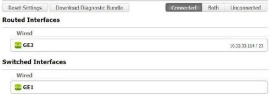
Underneath the device diagram, the status of the WAN and LAN connections display. In this area, you can change the display by clicking the Connected, Both, or Unconnected buttons.
If you click a WAN connection, a properties page for that connection opens.
NOTE: You can also download a diagnostic bundle from the Overview page by clicking the Download Diagnostic Bundle button. Open the Reset Settings page by clicking the Reset Settings button.
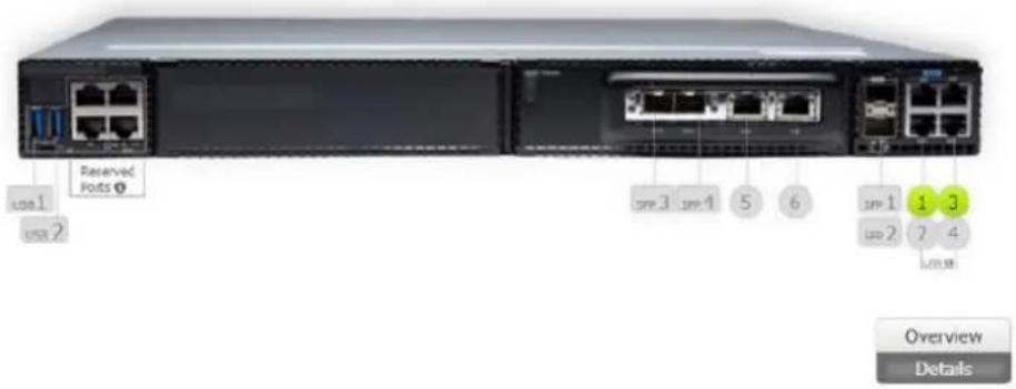
Edge Overview
Properties
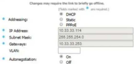
If you click a WAN connection from the Overview page (such as GE3 in this example), a Properties page for that connection displays.
From the Properties page, you can view status information and change the connection properties. For example, you can specify a static IP address for the interface, or select a PPPoE for the connection. However, Dell EMC recommends entering static and PPPoE values using Device Settings override on the Orchestrator.
When you finish changing the properties, click the Save Changes button. To return to the previous screen, click the << Return button.
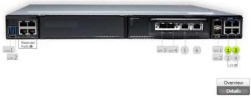
GE3 Properties

Status
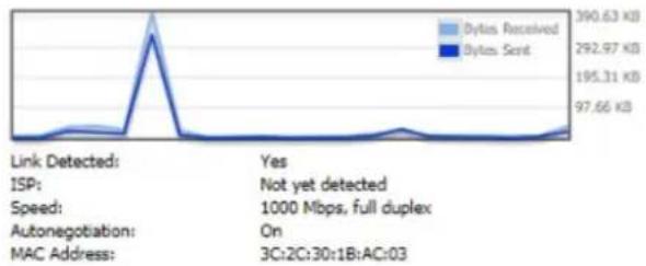
line
| Category | Value | | ------------------ | --------- | | Link Detected | 390.63 KB | | ISP | Not yet detected | | Speed | 1000 Mbps, full duplex | | Autonegotiation | On | | MAC Address | 3C:2C:30:1B:AC:03 |Configuration
Reset settings
The Reset Settings page has the following buttons:
- Identify—Flashes the platform lights for 30 seconds to help you locate the Edge.
- Restart Service—Restarts the VMware SD-WAN by VeloCloud service.
- Reboot—Initiates a reboot of the platform. When the service light illuminates again, the device has completed the reboot process.
- Reset Configuration—Returns the platform to an unactivated state. Cloud services are turned off, the platform is no longer associated with a cloud-managed configuration, and the initial default configuration reapplies.
- Hard Reset—Deactivates the platform, restores default configuration, and restores the original software version.
Specifications
This section lists the Edge 3000 Series platform specifications.
CAUTION: Operate the product at an ambient temperature not higher than 113^ F ( 45^ C).
CAUTION: Lithium Battery Caution: There is a danger of explosion if the battery is incorrectly replaced. Replace only with same or equivalent type of battery. Dispose of the batteries according to the manufacturer's instructions.
NOTE: For RoHS information, see Restricted Material Compliance.
Topics:
- Chassis physical design
- IEEE standards
- Agency compliance
• Safety standards and compliance agency certifications
• Product recycling and disposal
Chassis physical design
Table 3. Chassis physical design
Parameter Specifications
| Height 1.72 inches (43.7 cm) | |
| Width 17.1 inches (43.4 cm) | |
| Depth | 15 inches (38.1 cm)PSU/fan tray handle: 1.57 inches (40 mm) |
| Chassis weight with factory-installed components including one rNDC carrier card, one rNDC card, and one blank panel | · 16 core: 16.50 lbs (7.48 kg)—2 PSUs and 5 fans· 8 core: 16.60 lbs (7.53 kg)—2 PSUs and 4 fans |
| Rack clearance required | Front: 5 inches (12.7 cm)Back: 5 inches (12.7 cm) |
Table 4. Environmental parameters
Parameter Specifications
| Operating temperature 0°C to 45°C (32°F to 113°F) continuously | NOTE: Reduce maximum temperature by 1°C/125 meters (1°F/228 feet) above 950 meters (3,117 feet). |
| Operating humidity 5% to 85% (RH), non-condensing, continuously | 5% to 90% (RH), non-condensing, short termShort term is ≤slant 1% of operational hours per year. |
| Storage temperature -40°F to 70°C (-40°F to 158°F) | |
| Storage humidity 5% to 95%, non-condensing | |
| Maximum thermal output 300 W = 1024 BTU/Hr |
Parameter Specifications
| Maximum operational altitude | Maximum: 10,000 feet (3,048 meters)No performance degradation up to 3,117 feet (950 meters) |
| Maximum non-operational altitude 39,370 feet (12,000 meters) | |
| Shock SV0115 — ODM |
Table 5. AC power requirements
Parameter Specifications
| Power supply 100–240 VAC 50/60 Hz | |
| Typical current draw per platform | · 16 core: 110 VAC: 1.89 A |
| · 8 core: 110 VAC: 1.62 A | |
| · 16 core: 240 VAC: 0.87 A | |
| · 8 core: 240 VAC: 0.75 A | |
| Typical power consumption | · 16 core processor with five fans: 208 W |
| · 8 core processor with four fans: 178 W | |
| Maximum power consumption | · 16 core processor with five fans 312 W |
| · 8 core processor with four fans: 242 W | |
IEEE standards
The Edge 3000 Series complies with the following IEEE standards:
· 802.1ab—LLDP
· 802.1ax—Layer 2
· 802.1d, 802.1w, 802.1s, 802.1x—Mgmt/Security; 802.3x—Layer 2
· 802.3—1000BASE-KX
• 25G Etherenet Consortium 25
Agency compliance
The Edge 3000 Series complies with the following safety and agency requirements:
USA Federal Communications Commission statement
This equipment has been tested and found to comply with the limits for a Class A digital device, pursuant to Part 15 of the FCC rules. These limits are designated to provide reasonable protection against harmful interference when the equipment is operated in a commercial environment. This equipment generates, uses, and can radiate radio frequency energy. If it is not installed and used in accordance to the instructions, it may cause harmful interference to radio communications. Operation of this equipment in a residential area is likely to cause harmful interference, in which case users will be required to take whatever measures necessary to correct the interference at their own expense.
Properly shielded and grounded cables and connectors must be used in order to meet FCC emission limits. Dell EMC is not responsible for any radio or television interference caused by using other than recommended cables and connectors or by unauthorized changes or modifications in the equipment. Unauthorized changes or modification could void the user's authority to operate the equipment.
This device complies with Part 15 of the FCC Rules. Operation is subject to the following two conditions: (1) this device may not cause harmful interference, and (2) this device must accept any interference received, including interference that may cause undesired operation.
Industry Canada Class A emission compliance statement
This Class A digital apparatus complies with Canadian ICES-003.
Figure 2. Canadian Department of Communication Statement
FCC caution
Any changes or modifications not expressly approved by the party responsible for compliance could void the user's authority to operate this equipment. This transmitter must not be co-located or operating in conjunction with any other antenna or transmitter.
Radiation exposure statement
This equipment complies with FCC radiation exposure limits set forth for an uncontrolled environment. This equipment should be installed and operated with minimum distance 20cm between the radiator & your body.
NOTE: The country code selection is for non-US model only and is not available to all US model. Per FCC regulation, all WiFi product marketed in US must fixed to US operation channels only.
European Union EMC directive conformance statement
This product is in conformity with the protection requirements of EU Council Directive 2004/108/EC on the approximation of the laws of the Member States relating to electromagnetic compatibility. Dell EMC cannot accept responsibility for any failure to satisfy the protection requirements resulting from a non-recommended modification of this product, including the fitting of non-Dell EMC option cards.
This product has been tested and found to comply with the limits for Class A Information Technology Equipment according to CISPR 32/CISPR34 and EN55032 / EN55034. The limits for Class A equipment were derived for commercial and industrial environments to provide reasonable protection against interference with licensed communication equipment.
NOTE: This is a Class A product. In a domestic environment, this device may cause radio interference, in which case, you may be required to take adequate measures.
European Community Contact
Dell EMC, EMEA - Central
Dahlienweg 19
66265 Heusweiler
Germany
Tel: +49 172 6802630
Email: EMEA Central Sales
Japan VCCI compliance for class A equipment
Figure 3. Japan: VCCI compliance for class A equipment
This is Class A product based on the standard of the Voluntary Control Council For Interference by Information Technology Equipment (VCCI). If this equipment is used in a domestic environment, radio disturbance may arise. When such trouble occurs, the user may be required to take corrective actions.

NOTE: Use the AC power cords with Dell EMC equipment only. Do not use Dell EMC AC power cords with any unauthorized hardware.
Korean certification of compliance
Korean certification of compliance
| [equipment type] | |
| 품명(Product Name) | Ethernet Switch |
| 모델명(Model) | [model number] |
| 신청인(Applicant) | Dell Technologies |
| 제조자(Manufacturer) | [Manufacturer] |
| 제조년월(Manufacturing Date) | [date] |
| 제조국(Country of Origin) | China |
Figure 5. Korean package label
Radio compliance certificate
Korea (Korean warning statement is only required for devices contain 2400\~2483 and/or 5725\~5825 MHz radios)
Korean radio compliance certificate
Safety standards and compliance agency certifications
· CUS UL 60950-1, 2nd Edition
• CSA 60950-1-03, 2nd Edition
· EN 60950-1, 2nd Edition
· IEC 62368-1
· EN 60825-1, 1st Edition
- EN 60825-1 Safety of Laser Products—Part 1: Equipment Classification Requirements and User's Guide
· EN 60825-2 Safety of Laser Products—Part 2: Safety of Optical Fibre Communication Systems
· FDA Regulation 21 CFR 1040.10 and 1040.11
• IEC 60950-1, 2nd Ed, including all National Deviations and Group Differences
Product recycling and disposal
You must recycle or discard this platform according to applicable local and national regulations. Dell EMC encourages owners of information technology (IT) equipment to responsibly recycle their equipment when it is no longer needed. Dell EMC offers a variety of product return programs and services in several countries to assist equipment owners in recycling their IT products.
Waste electrical and electronic equipment (WEEE) directive for recovery, recycle and reuse of IT and telecommunications products
Dell EMC platforms are labeled in accordance with European Directive 2002/96/EC concerning waste electrical and electronic equipment (WEEE). The Directive determines the framework for the return and recycling of used platforms as applicable throughout the European Union. This label is applied to various products to indicate that the product is not to be thrown away, but rather reclaimed upon end of life per this Directive.

Figure 6. The European WEEE symbol
In accordance with the European WEEE Directive, electrical and electronic equipment (EEE) is to be collected separately and to be reused, recycled, or recovered at end of life. Users of EEE with the WEEE marking per Annex IV of the WEEE Directive, as shown above, must not dispose of end of life EEE as unsorted municipal waste, but use the collection framework available to customers for the return, recycling and recovery of WEEE. Customer participation is important to minimize any potential effects of EEE on the environment and human health due to the potential presence of hazardous substances in EEE.
Dell EMC products, which fall within the scope of the WEEE, are labeled with the crossed-out wheelie-bin symbol, as shown above, as required by WEEE.
For information on Dell EMC product recycling offerings, see the WEEE Recycling instructions on Support. For more information, contact the Dell EMC Technical Assistance Center.
Dell EMC support
The Dell EMC support site provides documents and tools to help you effectively use Dell EMC equipment and mitigate network outages. Through the support site you can obtain technical information, access software upgrades and patches, download available management software, and manage your open cases. The Dell EMC support site provides integrated, secure access to these services.
To access the Dell EMC support site, go to www.dell.com/support/. To display information in your language, scroll down to the bottom of the web page and select your country from the drop-down menu.
- To obtain product-specific information, enter the 7-character service tag, or the 11-digit express service code of your platform and click submit.
To view the platform service tag or express service code, pull out the luggage tag on the upper-right side of the platform or retrieve it remotely using the ipmitool -H
• To receive more technical support, click Contact Us. On the Contact Information web page, click Technical Support.
To access documentation, go to www.dell.com/manuals/.
To search for drivers and downloads, go to www.dell.com/drivers/.
To participate in Dell EMC community blogs and forums, go to www.dell.com/community.

- Dell EMC SD-WAN Edge 3000 Series Installation Guide
- Contents
- About this guide....5
- Site preparations....12
- Edge 3000 Series installation....14
- Platform setup....20
- Power supplies....22
- Fans....24
- Management ports....26
- User interface....28
- Specifications.... 31
- Dell EMC support.... 36
- About this guide
- Regulatory
- Topics:
- Related documents
- Information symbols
- Edge 3000 Series
- Introduction
- Features
- Physical dimensions
- LEDs
- Prerequisites
- Luggage tag
- Site preparations
- Site selection
- Cabinet placement
- Rack mounting
- Platform ground
- Fans and airflow
- Power
- Processor power button
- Storing components
- Edge 3000 Series installation
- Unpack
- Ground lug
- Rack or cabinet hardware installation
- Rack mount safety considerations
- Two-post installation
- 1U front-rack installation
- Four-post installation
- Optics installation
- Optics removal
- Platform power-up
- Power up sequence
- Platform setup
- Power supplies
- Components
- PSUs
- AC power supply installation
- AC power supply replacement
- Fans
- Fan LEDs
- Fan module installation
- Fan module replacement
- Management ports
- RS-232 console port access
- MicroUSB-B console port access
- User interface
- Overview
- Edge Overview
- Properties
- Reset settings
- Specifications
- Chassis physical design
- IEEE standards
- Agency compliance
- USA Federal Communications Commission statement
- Industry Canada Class A emission compliance statement
- Figure 2. Canadian Department of Communication Statement
- FCC caution
- Radiation exposure statement
- European Union EMC directive conformance statement
- Japan VCCI compliance for class A equipment
- Figure 3. Japan: VCCI compliance for class A equipment
- Korean certification of compliance
- Radio compliance certificate
- Safety standards and compliance agency certifications
- Product recycling and disposal
- Waste electrical and electronic equipment (WEEE) directive for recovery, recycle and reuse of IT and telecommunications products
- Dell EMC support
Brand : DELL
Model : Edge 3800
Category : Router