INV400012 - Power inverter HQ - Free user manual and instructions
Find the device manual for free INV400012 HQ in PDF.
| Product Type | DC to AC Power Converter (Power Inverter) |
| Brand | HQ |
| Model | INV400012 |
| Continuous Output Power | 4000 W |
| Peak Power (Surge) | 8000 W |
| DC Input Voltage | 12 V (10~16 V) or 24 V (20~30 V) depending on version |
| AC Output Voltage | 230 V AC |
| Output Waveform | Modified Sine Wave |
| Output Frequency | 50 or 60 Hz |
| Standby Current | < 1 A (12 V), < 0.8 A (24 V) |
| Efficiency | 85% ~ 90% |
| Protections | Short circuit, reverse polarity (via fuse), input overvoltage, low battery, low battery cutoff, overload, overheat |
| Cooling | Temperature controlled fan |
| Internal Fuses | 30 A x 18 (12 V) or 15 A x 18 (24 V) |
| Number of AC Outlets | 2 |
| Dimensions (L x W x H) | 580 x 210 x 159 mm |
| Weight | 11.2 kg |
| Power Source | External DC battery (12 V or 24 V) |
| Main Features | DC to AC conversion, soft start, voltage/current/power/overheat/overload indicators, remote on/off |
| Maintenance and Cleaning | Clean with a dry cloth; do not use solvents or abrasives |
| Safety | Do not open the case; do not expose to water or moisture; dangerous AC wiring when powered |
| Spare Parts and Repairability | Fuses replaceable by a qualified electrician; other repairs by authorized technician |
| General Information | Designed for horizontal or vertical installation; do not obstruct ventilation; use appropriate wiring (12 V: #38x2, 24 V: #38x1) |
Frequently Asked Questions - INV400012 HQ
User questions about INV400012 HQ
0 question about this device. Answer the ones you know or ask your own.
Ask a new question about this device
Download the instructions for your Power inverter in PDF format for free! Find your manual INV400012 - HQ and take your electronic device back in hand. On this page are published all the documents necessary for the use of your device. INV400012 by HQ.
USER MANUAL INV400012 HQ
natural_image
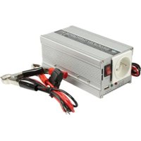
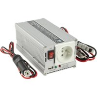
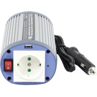
Exterior view of a power supply unit with two AC outlets and red-black connectors, connected to a white terminal (no visible text or symbols)MANUAL (p. 2)
DC to AC power inverter
MODE D'EMPLOI (p. 12)
MANUAL DE USO (p. 29)
Conversor de corriente CC a CA
KÄYTTÖOHJE (s. 39)
DC - AC Invertteri
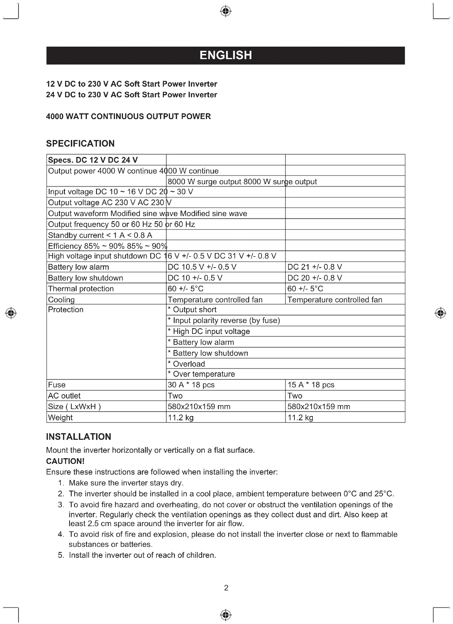
| Specs. DC 12 V DC 24 V | ||
| Output power 4000 W continue 4000 W continue | ||
| 8000 W surge output 8000 W surge output | ||
| Input voltage DC 10 ~ 16 V DC 20 ~ 30 V | ||
| Output voltage AC 230 V AC 230 V | ||
| Output waveform Modified sine wave | ||
| Output frequency 50 or 60 Hz 50 or 60 Hz | ||
| Standby current < 1 A < 0.8 A | ||
| Efficiency 85% ~ 90% 85% ~ 90% | ||
| High voltage input shutdown DC 16 V +/- 0.5 V DC 31 V +/- 0.8 V | ||
| Battery low alarm | DC 10.5 V +/- 0.5 V | DC 21 +/- 0.8 V |
| Battery low shutdown | DC 10 +/- 0.5 V | DC 20 +/- 0.8 V |
| Thermal protection | 60 +/- 5°C | 60 +/- 5°C |
| Cooling | Temperature controlled fan | Temperature controlled fan |
| Protection | * Output short | |
| * Input polarity reverse (by fuse) | ||
| * High DC input voltage | ||
| * Battery low alarm | ||
| * Battery low shutdown | ||
| * Overload | ||
| * Over temperature | ||
| Fuse | 30 A * 18 pcs | 15 A * 18 pcs |
| AC outlet | Two | Two |
| Size ( LxWxH ) | 580x210x159 mm | 580x210x159 mm |
| Weight | 11.2 kg | 11.2 kg |
INSTALLATION
Mount the inverter horizontally or vertically on a flat surface.
CAUTION!
Ensure these instructions are followed when installing the inverter:
- Make sure the inverter stays dry.
- The inverter should be installed in a cool place, ambient temperature between 0°C and 25°C.
- To avoid fire hazard and overheating, do not cover or obstruct the ventilation openings of the inverter. Regularly check the ventilation openings as they collect dust and dirt. Also keep at least 2.5 cm space around the inverter for air flow.
- To avoid risk of fire and explosion, please do not install the inverter close or next to flammable substances or batteries.
- Install the inverter out of reach of children.
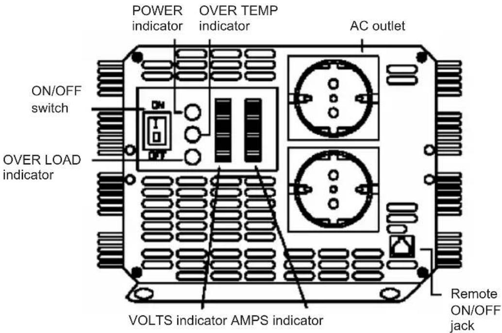
OPERATION OUTPUT PANEL INSTRUCTIONS
text_image
POWER indicator OVER TEMP indicator AC outlet ON/OFF switch OVER LOAD indicator VOLTS indicator AMPS indicator Remote ON/OFF jackON/OFF switch
For turning the inverter on/off.
Remote ON/OFF jack
Allows you to mount the inverter out of sight and turn ON or OFF with the remote control (included).
Battery voltage (VOLTS) indicator
The battery voltage indicator displays the voltage at the input terminal of the inverter.
Battery current (AMPS) indicator
The battery current indicator displays the current drawn from the battery by the inverter. Current should be in the green zone for continuous operation. In the yellow zone the inverter will work for several minutes, in the red zone the inverter protection will shut down the inverter.
POWER indicator
When connected to a battery and switched on, the power indicator is illuminated in green: ready for use.
OVER TEMPERATURE indicator
The over temperature indicator is illuminated in yellow when the inverter is overheated. An alarm will also sound and the inverter will shutdown.
Overheating is caused by operating the inverter with power levels above 4000 W continuous output. It will also occur when it is installed somewhere where it cannot lose its heat properly. The inverter will automatically restart when cooled down.
OVERLOAD indicator
The indicator is illuminated in red when an overload occurs. The problem can be solved by switching the inverter off and reducing the load before switching it on again.
AUDIBLE ALARM
Alarm will sound in the case of:
a. Over temperature
b. Low battery (<10.5 V for 12 V inverter, <21 V for 24 V inverter)
c. Low battery shutdown (<10 V for 12 V inverter, <20 V for 24 V inverter)
INPUT PANEL AND INSTRUCTION
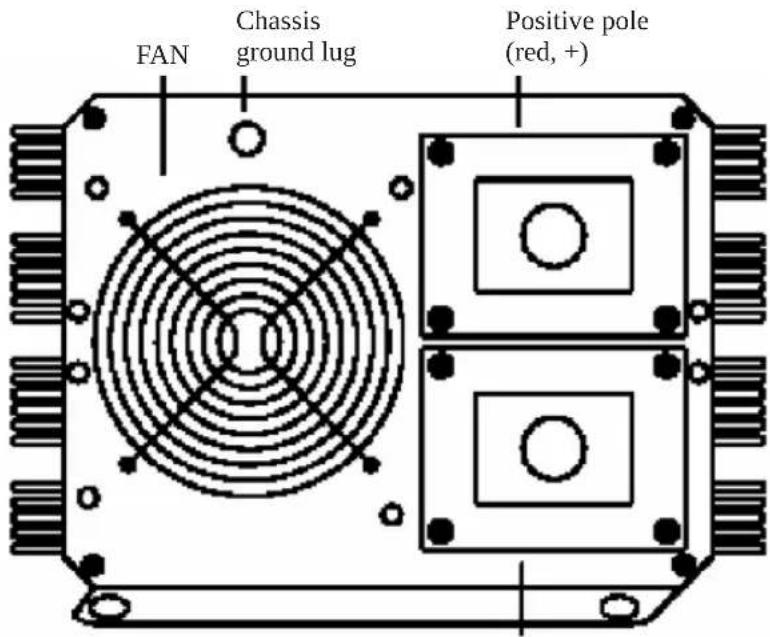
text_image
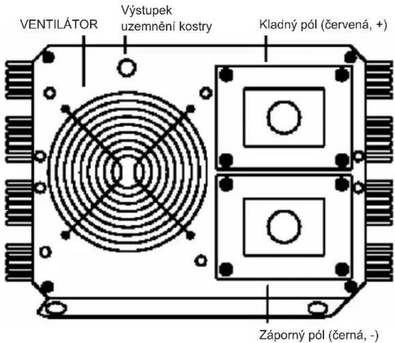
FAN Chassis ground lug Positive pole (red, +)Negative pole (black, -)
FAN
For cooling the inverter during operation.
TERMINAL CONNECTOR
Use the red battery cable to connect (+) of the battery to the (+) terminal of the inverter. Then use the black battery cable to connect the (-) of the battery to the (-) terminal of the inverter. Tighten the screws of the DC input cables rmly.
When connected to a battery, please make sure to turn on the inverter before turning on the connected appliance(s). When using the inverter with several appliances at the same time, turn the appliances on separately after the inverter is already turned on. This will ensure that the inverter doesn't have to deliver start up currents for the loads all at once.
CAUTION!
Please note that 230 V AC power is potentially lethal. Do not work on AC wiring while it is connected to the inverter (even if it is switched off), unless the DC power source is physically disconnected from the inverter. Do not work on AC wiring if it is connected to another AC power source such as a generator or utility line.
CAUTION!
Do not reverse input! Do not use "alligator-clips" and always ensure the ON/OFF switch on the output panel of the inverter is switched to the OFF position before connecting a battery or another DC power source!
CHASSIS GROUND LUG
The inverter has a lug to connect the chassis with the inverter. The ground wire in the AC junction box on the output panel of the inverter is connected to the chassis.
The chassis ground lug must be connected to a grounding point, which will vary depending on where the inverter is installed. In a vehicle, connect the chassis ground lug to the chassis of the vehicle. In a boat, connect to the boat's grounding system. In a xed location, connect to earth ground by a ground rod (a metal rod pounded into the earth), or other proper service entrance ground. Use a #12 AWG or larger copper wire (preferably with green/yellow insulation) to connect the chassis ground lug to the grounding point.
The neutral (common) conductor of the inverter's AC output circuit is connected to chassis ground. Therefore, when the chassis is connected to ground, the neutral conductor will also be grounded. This conforms to national electrical code requirements that separately derived AC sources (such as inverters and generators) have their neutral conductors tied to ground in the same way that the neutral conductor from the utility line is tied to ground at the AC breaker panel.
CAUTION!
Don't operate the 4000 W inverter without connecting it to ground. Electrical shock hazard may result.
TROUBLESHOOTING
| Problems Possible causes Solutions | ||
| 1) Low voltage output Using an average reading volt meter | Use true RMS reading meter | |
| 2) Low voltage output and AMPS indicator in red zone | Overload Reduce load | |
| 3) No voltage output and VOLTS indicator in lower red zone | Low voltage input Recharge battery, check connections and cable | |
| 4) No voltage output and POWER indicator no light | a. Inverter switched off Turn inverter on | |
| b. No power to inverter Check wiring to inverter and battery | ||
| c. Internal fuse open Have qualified electrician to check and replace | ||
| d. Reverse DC polarity Have qualified electrician to check and replace fuse, please observe correct polarity | ||
| 5) No voltage output and VOLTS indicator in upper red zone | High voltage input Make sure that inverter is connected to 12 V battery (24 V for 4000 W/24 V inverter) and check regulation of charging system | |
| 6) Low battery alarm on all the time and VOLTS indicator below 10.5 V (21 V for 4000 W/24 V inverter) | a. Poor DC wiring Use proper cable and make solid connections | |
| b. Poor battery condition | Change battery or use new battery | |
| 7) No voltage output, OVER TEMP indicator light and load in excess of 4000 W/250 amperes current input (or 125 A for 4000 W / 24 V inverter) | Thermal shutdown Allow inverter to cool down and reduce load if continuous operation required | |
| 8) No voltage output, OVER TEMP indicator light and load less than 4000 W/250 amperes current input (or 125 A for 4000 W/24 V inverter ) | Thermal shutdown Make sure ventilation openings in inverter are not blocked and reduce ambient temperature. | |
| 9) No voltage output and OVER LOAD indicator light | a. Short circuit or wiring error | Check AC wiring for short circuit or improper polarity |
| b. Very high power load | Remove or reduce load | |
If, after the above troubleshooting, this inverter still does not work, please return it to us or have a qualified electrician to check and replace. Don't open the case or cut out the cord.
CAUTION:
Do not use the inverter with the following rechargeable appliances:
Two particular types of chargers for small nickel cadmium batteries can be damaged if connected to the inverter:
a. Small battery operated appliances such as flashlights, razors and nightlights that can be plugged directly into the AC receptacle to recharge.
b. Certain battery chargers for battery packs used in hand power tool. These chargers will have a warning label stating that dangerous voltages are present at the battery terminals.
This problem doesn't occur with the vast majority of battery operating equipment. Most of these equipments use a separate charger or transformer that is plugged into the AC receptacle and produces the lower voltage output. If the label on the AC adapter or charger states that produces the low AC or DC voltage output (less than 30 volts), the inverter will power this adapter or charger safely without trouble.
USE THE CORRECT WIRING AND TYPE OF BATTERY!
For most applications of 4000 W inverter it is recommended to use one big deep cycle battery or more in parallel. More capacity is better because there will be more reserve capacity to prevent the battery to be discharged too far.
Recommended ampere input:
12 V → 366 A
24 V → 183 A
Recommended DC wiring cable:
12 V → #38x2
24 V → #38x1
Safety precautions:


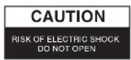

To reduce risk of electric shock, this product should ONLY be opened by an authorized technician when service is required. Disconnect the product
from mains and other equipment if a problem should occur. Do not expose the product to water or moisture.
Maintenance:
Clean only with a dry cloth. Do not use cleaning solvents or abrasives.
Warranty:
No guarantee or liability can be accepted for any changes and modifications of the product or damage caused due to incorrect use of this product.
General:
Designs and specifications are subject to change without notice.
All logos brands and product names are trademarks or registered trademarks of their respective holders and are hereby recognized as such.
Keep this manual and packaging for future reference.
Attention:
This product is marked with this symbol. It means that used electrical and electronic products should not be mixed with general household waste. There is a separate collections system for these products.
DEUTSCH
VSTUPNÍ PANEL A POKYNY

The Ground Truth image displays a single, solid horizontal line. According to Rule 2 (UNDERSCORE & LINE RULES), this is a stylistic or background line, not a placeholder underscore. Therefore, the OCR result must ignore it and output nothing or only meaningful text. The provided OCR content is "____", which consists of four underscores. This is an incorrect interpretation of the line as a placeholder, violating the rule that stylistic lines must be ignored. The OCR has hallucinated underscores where none should exist based on the GT's visual context. Hence, the OCR result is inconsistent with the Ground Truth.
Description: DC to AC power inverter