Syslite KAL II - Lamp FESTOOL - Free user manual and instructions
Find the device manual for free Syslite KAL II FESTOOL in PDF.

| Product type | Compact LED work light |
| Brand | Festool |
| Model | Syslite KAL II |
| Lighting | 12 LED Power (1.5 W each) |
| Luminous flux (level 1) | 310 lumens (30%) |
| Luminous flux (level 2) | 769 lumens (100%) |
| Lighting duration (internal battery, level 1) | 4 h 50 min |
| Lighting duration (internal battery, level 2) | 2 h |
| Internal battery capacity | Li-ion 7.2 V / 2.9 Ah |
| Operating voltage (external battery) | 10.8 - 19 V |
| Charging time (to 90% / 100%) | 2 h 40 min / 3 h 20 min |
| Operating temperature range | -5 °C to +55 °C |
| Charging temperature range | 0 °C to +45 °C |
| Weight (without external battery) | 0.7 kg |
| Protection class | IP 2X |
| Energy efficiency class of the light source | E |
| Power supply | Internal or external Festool battery (BPC/BPS), mains adapter 100-240 V |
| Main functions | 3 lighting levels, energy-saving mode, voltage and temperature monitoring, power cut mode |
| Mounting | Foldable handle, magnetic base (optional), tripod UNC 1/4"-20 |
| Maintenance and cleaning | Clean the plastic disk with a soft, dry cloth; keep contacts clean |
| Safety | Do not look into the beam, do not cover, do not use in explosive environment, risk of magnetic crushing |
| Spare parts and repairability | Repair only by the manufacturer or authorized workshop, use original Festool parts |
| General information | Indoor use only; do not use on public roads |
Frequently Asked Questions - Syslite KAL II FESTOOL
User questions about Syslite KAL II FESTOOL
0 question about this device. Answer the ones you know or ask your own.
Ask a new question about this device
Download the instructions for your Lamp in PDF format for free! Find your manual Syslite KAL II - FESTOOL and take your electronic device back in hand. On this page are published all the documents necessary for the use of your device. Syslite KAL II by FESTOOL.
USER MANUAL Syslite KAL II FESTOOL
natural_image
Black and white FESTOOL device with illuminated screen and sensor array (no readable text or symbols)

721703_D / 2022-01-21
1
flowchart
graph TD
    A["4-1"] --> B["Sensor with 4"]
    B --> C["3D Camera with 2"]
    C --> D["3D Sensor with 1"]
    D --> E["3D Display with 2"]
1 Symbole

Warning of general danger
Warning of electric shock

Read the operating manual and safety warnings.
CAUTION! Do not look directly into the light beam!
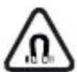
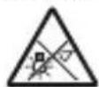
Warning against magnetic field!

Prohibited for people with pacemaker
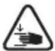
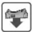
Risk of pinching fingers and hands!

For indoor use only
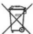
Do not dispose of it with domestic waste.
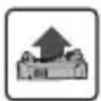
Inserting the battery pack
Removing the battery pack

Handling instruction

Tip or advice

UKCA marking: The United Kingdom Conformity Assessed symbol is a marking for products being placed on the market in the United Kingdom. It is a manufacturers indication that the product is in conformance with the relevant regulations in the UK.
2 Safety warnings

WARNING! Read and observe all information and safety instructions. Failure to observe the information and safety instructions may lead to electric shocks, fires and/or serious injuries.
Keep all safety information and instructions for future reference.
- Handle the device with care. The device may generate heat which increases the risk of fire and explosions.
- Never use the device in potentially explosive environments.
- Do not cover the device when switched on. The device heats up during operation and can cause burns.
Warning of harmful light on. Do not look into the light for long periods. Do not die light beam towards other or animals. Optical radiation damage the eyes.
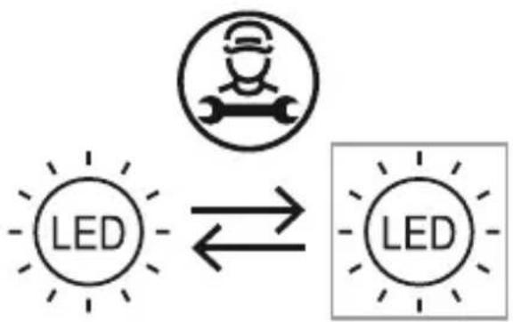
- Have your device repaired by qualified specialist staff and always use original spare parts.
flowchart
graph LR
    A["Worker Icon"] --> B["LED"]
    B --> C["Worker Shape"]
    style A fill:#fff,stroke:#000
    style B fill:#fff,stroke:#000
    style C fill:#fff,stroke:#000
The light source fitted in this device must only be replaced by the manufacturer or a customer service workshop in order to ensure that your device operates reliably.
- Always use original Festool parts for repair and maintenance. The use of incompatible accessories or spare parts can result in electric shocks or other injuries.
- Do not use the device for illuminating the road. The device is not approved for illuminating the road.
- Always use compatible Festool battery packs in the working light. Using other battery packs poses a fire hazard and may cause personal injury.
- When charging the working light, do not use charging adapters from other manufacturers. Otherwise, there is a danger of fire and explosion.
- This device can be used by persons with reduced physical, sensory or mental abilities or those who lack
experience or knowledge, if they are supervised or have been instructed on safe use of the device and understand the resulting dangers. Children should always be supervised to ensure that they do not play with the device.
- Ensure stable footing or secure mounting when securing to a tripod or with a magnetic foot. In the event of unstable footing or insecure mounting, the working light may fall and cause personal injuries or material damage.
- Protect the battery pack from excessive heat or constant heat sources such as sunlight or naked flames. There is a risk of explosion.
- Never use water to extinguish burning Li-ion battery packs! Use sand or a fire blanket.
Follow the operating manual for the charger and the battery pack.
3 Intended use
The compact working light was specifically designed for illuminating dry areas in interior spaces.
The device is not suitable for illuminating rooms in residential buildings.

The user is liable for improper or non-intended use.
4 Technical data
Compact working light KAL II
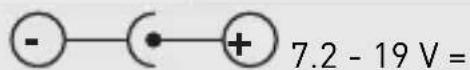
Rated voltage / capacity of integral battery (Lilon) 7.2 V = / 2.9 Ah
Rated voltage with external Festool battery pack 10.8 - 19 V =
Charging socket voltage range
| Compact working light KAL II |
| Lighting device 12x 1.5W Power LED |
| Light duration (internal battery) Min. light: Stage 1 (30%) 4 h 50 min. |
| Max. light: Stage 2 (100%) 2 h. |
| Luminous flux, brightness Min. light: Stage 1 (30%) 310 Lumen |
| Max. light: Stage 2 (100%) 769 Lumen |
| Charge time of internal battery 90% / 100% 2 h 40 min / 3 h |
| 20 min. |
| Permitted operating temperature range -5 °C to +55 °C |
| Permitted battery temperature for charging 0 °C to +45 °C |
| Weight (without external battery pack) 0.7 kg |
| Protection category IP 2X |
This tool has a light source of energy efficiency class E.
| Mains power pack BQ30A-1901200 | |
| Input voltage 100–240 V | |
| Input alternating current frequency 50–60 Hz | |
| Output voltage | 19 V DC |
| Output current | 1.2 A |
| Output | 22.8 W |
| Average efficiency in operation | 87% |
| Efficiency at low load (10%) | 84% |
| No-load power consumption | ≤ 0.078 W |
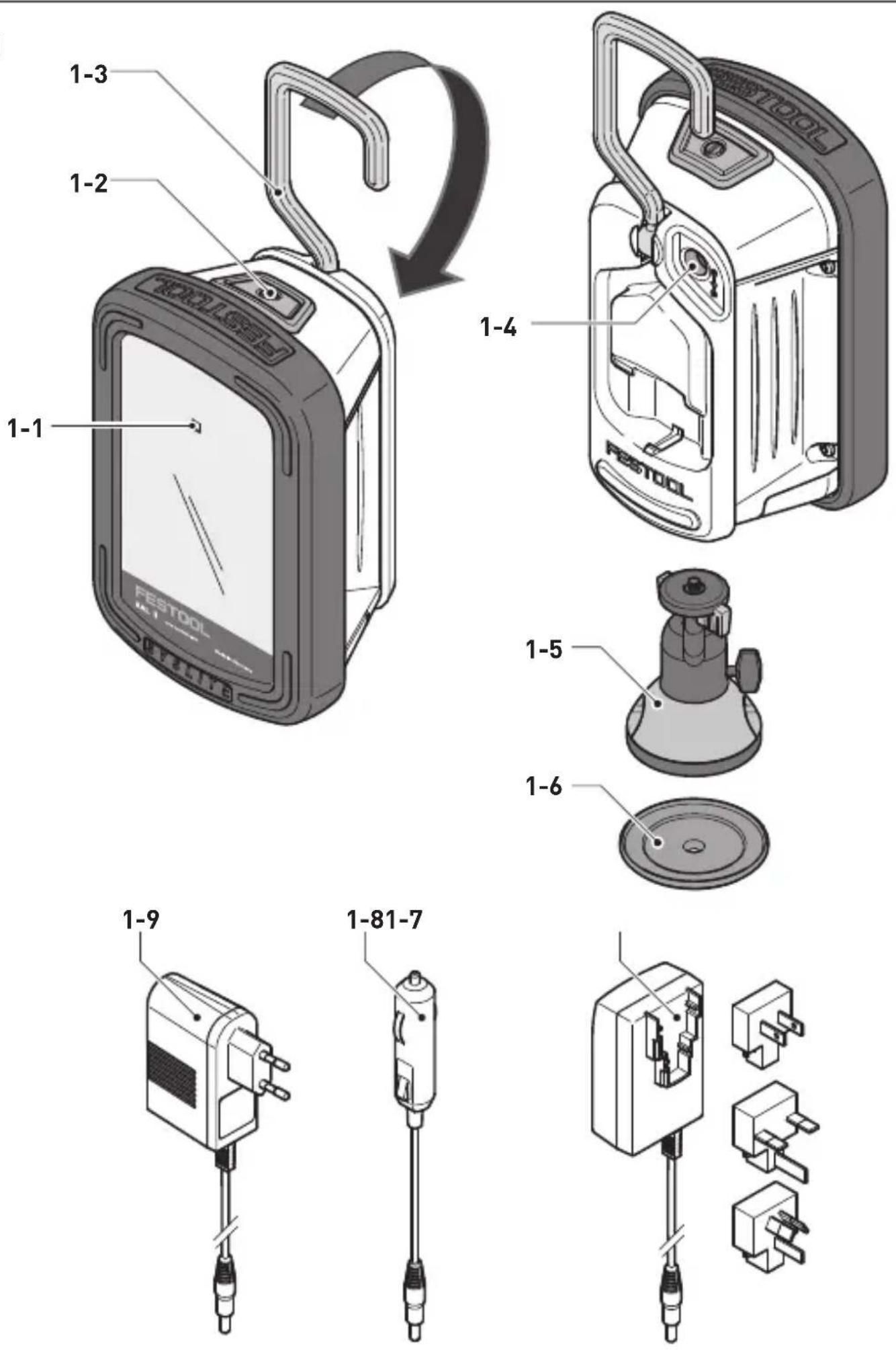
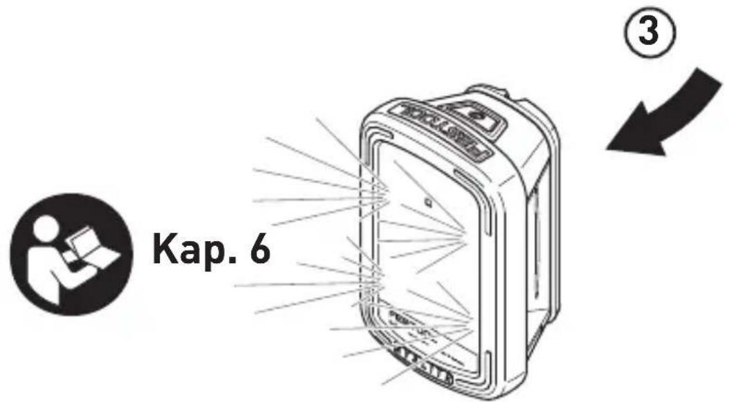
5 Machine features
[1-1] Charging state indicator LED
[1-2] On/off switch with 3 settings
[1-3] Folding attachment handle
[1-4] Connecting socket for charging adapter
[1-5] Magnetic foot with spherical head*
[1-6] Adapter plate*
[1-7] Specific charging adapter for country*
[1-8] Vehicle charging adapter
[1-9] Mains charging adapter*
[2-1] Threaded socket for tripod UNC 1/4"-20
English
* not on all versions included in the scope of delivery
Accessories shown or described are not always included in the scope of delivery. The illustrations specified are located at the beginning and end of the operating instructions.
6 Operation

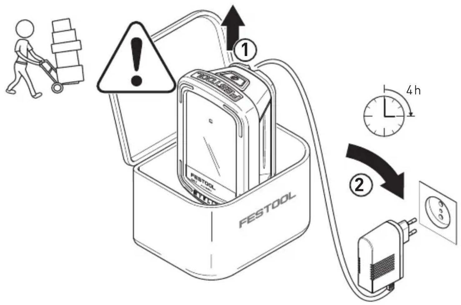
Prior to initial operation: charge battery pack for approx. 4 h!
6.1 Charging the integral battery pack
▶ Insert the mains or vehicle charging adapter into the connecting socket [1-4].
When the light is switched off, the charging state indicator LED [1-1] displays the operating state of the internal battery for the duration of the charging process:
LED green - flashing quickly
Charging internal battery at maximum rate.
LED green - flashing slowly
80% of internal battery capacity exceeded.
LED green - continuous light
Internal battery is charged to 90% and then charged fully at reduced power.
LED red - flashing
General fault indication, e.g. incomplete contact, short circuit, battery faulty.
LED red - continuous light
Battery temperature is outside the permitted range.
LED orange
Power failure mode, see chapter 6.5.
6.2 On/Off switch [1-2]
The ON/OFF switch [1-2] has three settings:
- Press once -> Switch on in lighting mode in energy-saving stage (Stage 1: 30%)
- Press twice -> Switch to max. luminosity (Stage 2: 100%)
- Press three times -> switch off
6.3 Voltage monitoring
If the minimum operating voltage is not met during lighting mode with either internal or external battery pack, the device shifts to emergency mode. It reduces luminosity and switches off after 2 minutes.
6.4 Temperature monitoring
If the device temperature does not remain within the specified limits, the working light switches to emergency mode. It reduces luminosity and then switches off after 2 minutes.
6.5 Power failure mode
The working light has a power failure mode. It automatically lights up the work area in the event of a sudden power failure.
▶ Hold down the ON/OFF switch [1-2] and insert the mains charging adapter or car charging adapter in the connector socket [1-4].
The working light turns off and the charging indicator switches to flashing orange (charging) or continuous orange (fully charged). depending on the operating state.
In the event of an interruption to the external voltage supply, the working light automatically switches on.
Switching off the mode:
▶ Press the ON/OFF switch [1-2] again.
Charging indicator switches to standard mode, see chapter 6.1.
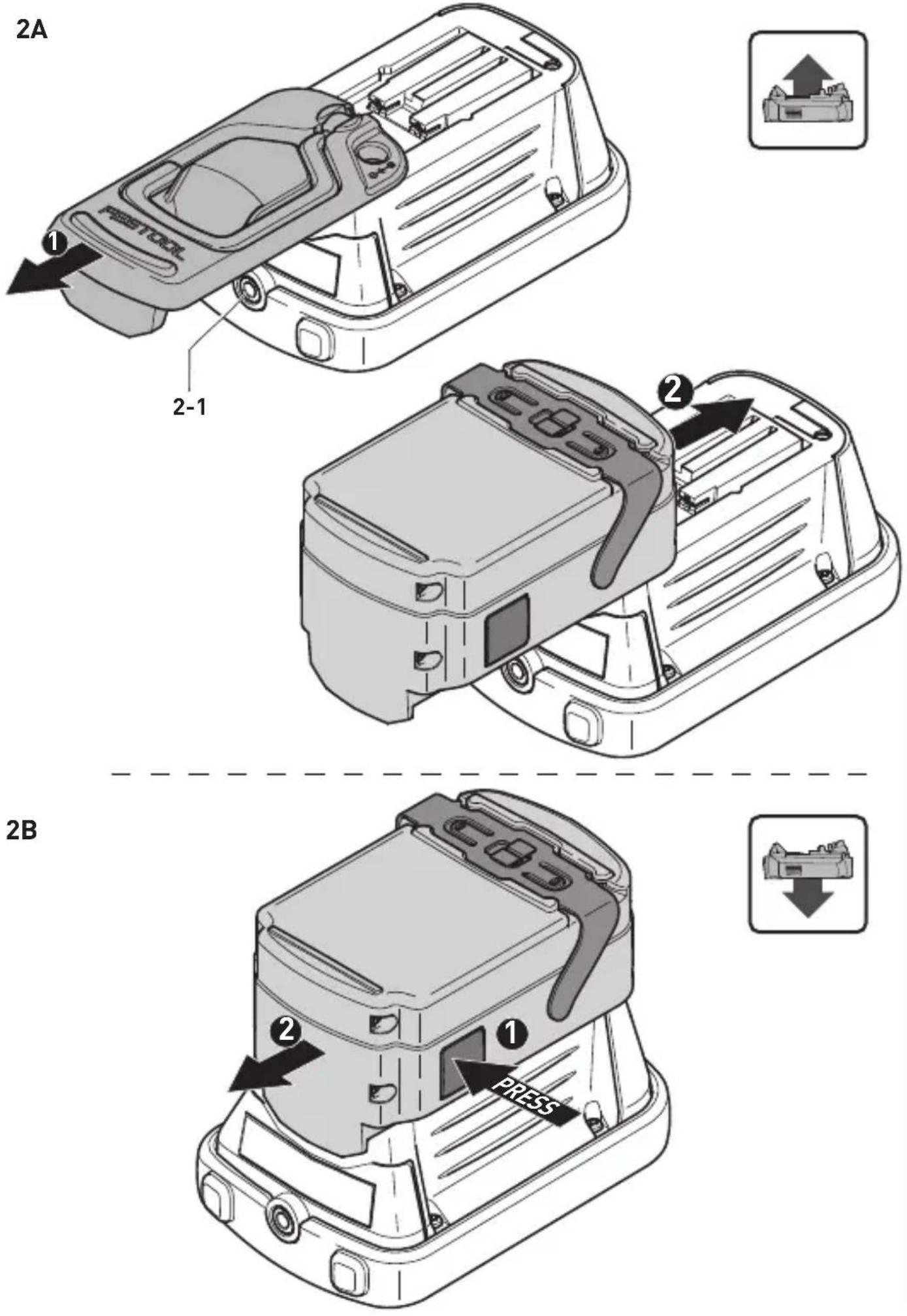
6.6 Operating with external Festool battery pack [2A] + [2B]
The working light can operate with any Festool battery pack from the BPC or BPS series. When connected to the external Festool battery pack, the working light only consumes power from this battery pack.
Only compatible Festool chargers can charge the Festool battery pack.
6.7 Setup options
Attachment handle [1-3]
The folding attachment handle allows you to hang the device from scaffolding or similar structures.
If you decide to power the device with an external Festool battery pack, the attachment handle must be detached beforehand [2A].
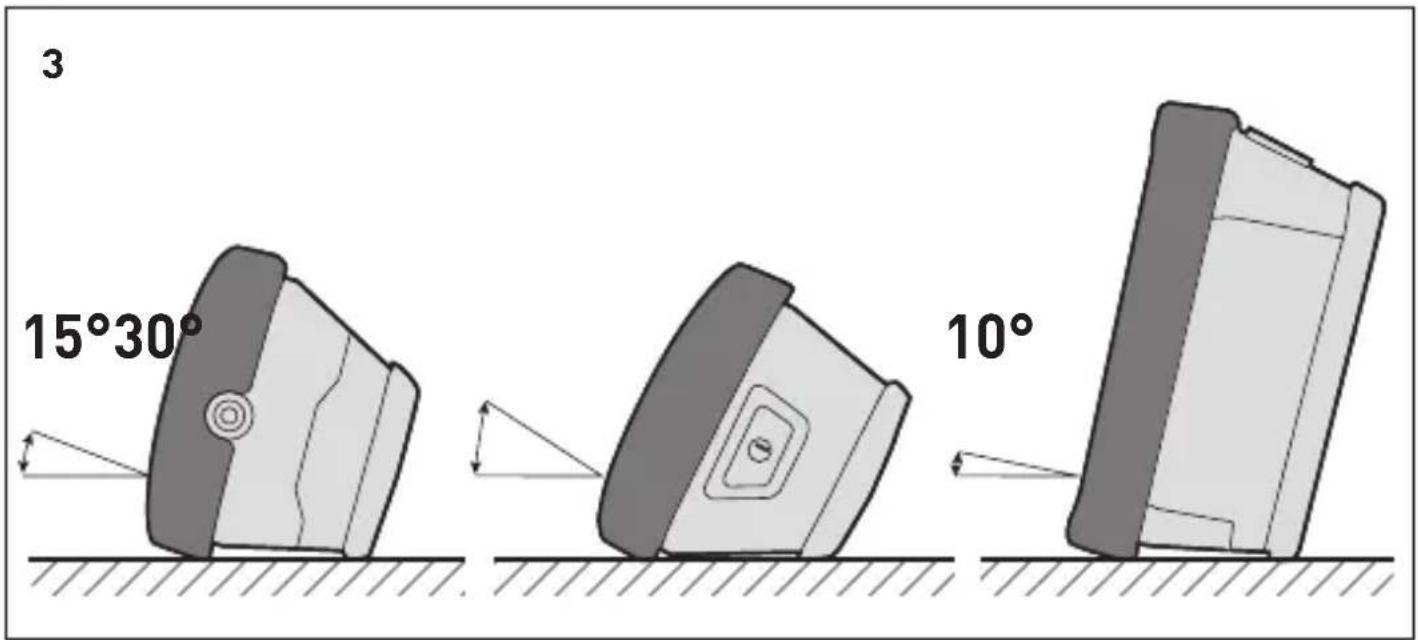
Setup angle
The working light can be set up in three different angles [3].
Tripod
A standard UNC 1/4"-20 photo tripod socket can be screwed onto the tripod socket bushing [2-1].
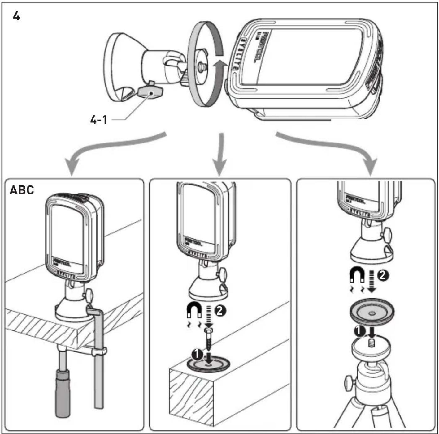
Magnetic foot with spherical head (part accessories) [4]
![FESTOOL Syslite KAL II - Magnetic foot with spherical head (part accessories) [4] - 1](/content/2026/04/604857/images/7bf02ea22116204fb8e5db68a0afaa5576d7ae319c0b0e9dbdcf18220c5408fa.jpg)
Strong magnetic fields may damage or destroy electronic or mechanical elements and devices. The same also applies to cardiac pacemakers. The required safety distances can be found in the manuals of these devices.
![FESTOOL Syslite KAL II - Magnetic foot with spherical head (part accessories) [4] - 2](/content/2026/04/604857/images/0f85a62a9369c4e50802ca978451e6417b3e306eb62f671b6d9a09d8f7692783.jpg)
Risk of pinching fingers and hands at the magnet!
Check the area at the magnetic foot before use and clean if necessary.
Only use the magnetic foot for securing the Festool working light using one of the options described below:
Screw on magnetic foot at the tripod socket [2-1]. This can be rotated in all directions by loosening the clamping screw [4-1].
Secure the magnetic foot using one of three options:
[4A] Secure with a clamp
[4B] Magnetic mounting at the screwed-on adapter plate
[4C] Magnetic mounting with the adapter plate screwed to its stand
7 Service and maintenance
Customer service and repairs must only be carried out by the manufacturer or service workshops. Find the nearest address
at: www.festool.co.uk/service
Always use original Festool spare parts. Order no. at: www.festool.co.uk/ service
- Always clean the plastic cover on the working light using a soft, dry
English
cloth to prevent any damage. Do not use solvents.
- Keep the contacts on the working light and battery pack clean.
- Always appoint an authorised service workshop to replace damaged integral batteries.
8 Environment
Prior to disposal
Remove the integral battery from the device! Dismantle the housing components and remove the battery. Dispose of the battery using our return service.
Do not dispose of electric power tools in household waste! recycle devices, accessories and packaging. Observe applicable country-specific regulations.
EU only: In accordance with European Directive on waste electrical and electronic equipment and implementation in national law, used electric power tools must be collected separately and handed in for environmentally friendly recycling.
Return used or faulty battery packs to your local specialist retailer, Festool after-sales service or nearest public waste disposal facility (observe applicable regulations). Battery packs will then be recycled.
EU only: In accordance with the European Directive on batteries and implementation in national law, defective or used battery packs/batteries must be collected separately and handed in for environmentally friendly recycling.
Information on REACH:
www.festool.com/reach
9 Transportation
The Li-ion battery packs included are subject to the requirements of the legislation on hazardous goods. The user must familiarise themselves with the local regulations prior to transport. Special requirements apply to shipping via third parties (e.g. air transport or haulage) and these must be observed. When preparing the item to be sent, a dangerous goods expert must be consulted. Only return the battery pack if it is undamaged. Observe local regulations when shipping. Observe any further national regulations.
10 General information
Imported into the UK by
Festool UK Ltd
1 Anglo Saxon Way
Bury St Edmunds
IP30 9XH
Great Britain
1 Symboles

[1-6] Plaque adaptatrice*
- 3 pressions -> désactivation
flowchart
graph TD
    A["LED"] --> B["Worker Icon"]
    B --> C["LED"]
Head of Product Development

Ralf Brandt
Head of Product Conformity
Declaration of Conformity
We as the manufacturer Festool GmbH, Wertstraße 20, 73240 Wendlingen, Germany declare under our sole responsibility that the product[s]:
Designation: Compact portable work light with LED's
(with power supply GA 190012E or BQ30A-1901200)
Designation of Type[s]: SYSLITE KAL II
Serial number[s] ^1 : 10016198
fulfills all the relevant provisions of the following UK Regulations:
• S.I. 2016/1101 Electrical Equipment (Safety) Regulations 2016
• S.I. 2016/1091 Electromagnetic Compatibility Regulations 2016
• S.I. 2010/2617 The Ecodesign for Energy-Related Products Regulations 2010
• S.I. 2012/3032 Restriction of the Use of Certain Hazardous Substances in Electrical and Electronic Equipment Regulations 2012
and are manufactured in accordance with the following designated standards:
• BS EN 60598-1:2015+A1:2018
• BS EN 60598-2-4:2018
• BS EN 62368-1:2014 + A11:2017
• BS EN IEC 62031:2020
• BS EN IEC 55015:2019 + A11:2020
• BS EN IEC 61000-3-2:2019
• BS EN 61000-3-3:2013
• BS EN 61547:2009
• BS EN 62471:2008
• BS EN 50563:2011+A1:2013
• BS EN IEC 63000:2018
^1 in the specified serial number range [S-Nr.] from 400000000 - 499999999

Place and date of declaration: Wendlingen, 15.04.2021
Signed on behalf of and in name of Festool GmbH
Markus Stark
Head of Productdevelopment

Ralf Brandt
Head of Productconformity
FESTOOL GmbH
Wertstraße 20
D-73240 Wendlingen
Tel.: 07024/804-0
Telefax: 07024/804-20608
E-Mail: info@ festool.com
www.festool.com