
TT1600 - Transport cart BARTSCHER - Free user manual and instructions
Find the device manual for free TT1600 BARTSCHER in PDF.
| Product type | Tray transport/storage cart |
| Brand | Bartscher |
| Model | TT1600 |
| Item number | 300083 |
| Material | Chrome-nickel steel |
| Dimensions (L x D x H) | 925 x 620 x 1700 mm |
| Weight | 38.0 kg |
| Maximum total load | 48 kg |
| Recommended load per slide | 3.0 kg |
| Number of slides | 16 (2 x 8) |
| Slide dimensions | 500 x 360 mm |
| Tray compatibility | GN 1/1 containers or standard cafeteria trays 443 x 343 mm |
| Spacing between slides | 145 mm |
| Caster type | 4 swivel casters, ∅125 mm, rubber tread |
| Casters with brake | 2 (mounted diagonally) |
| Handle | On one side, for easy storage |
| Top shelf | With guardrail, L 775 x D 530 x H 150 mm |
| Bottom shelf | Included |
| Care and cleaning | Soft, damp cloth; no abrasive products |
| Safety | Caster brakes to lock the cart |
| Assembly | Assembly required, Allen key provided |
| Country of manufacture | Germany (Bartscher GmbH) |
Frequently Asked Questions - TT1600 BARTSCHER
User questions about TT1600 BARTSCHER
0 question about this device. Answer the ones you know or ask your own.
Ask a new question about this device
Download the instructions for your Transport cart in PDF format for free! Find your manual TT1600 - BARTSCHER and take your electronic device back in hand. On this page are published all the documents necessary for the use of your device. TT1600 by BARTSCHER.
USER MANUAL TT1600 BARTSCHER
natural_image
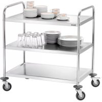
Exterior view of a stainless steel multi-compartment food cart with metal racks and wheels (no text or symbols visible)300083
Tray transport trolley/ clearing trolley
ENGLISH ____ from page 5 to 8
natural_image
Technical line drawing of a mechanical component with a 5-inch angle and label D (no text or symbols beyond basic geometry)natural_image
Exterior view of a stainless steel storage cabinet with metal grilles and rack-mounted compartments (no visible text or symbols)Service-Hotline: 0180 5 971 197
| Name: | Tray transport trolley/clearing trolley |
| Article number: | 300083 |
| Material: | Chrome nickel steel |
| Construction: | 4 rubber swivel wheels, ∅ 125 mm,2 swivel wheels with brakes,Shelf with railing: W 775 x D 530 x H 150 mmone-way handle for easy moving |
| Slots: | can hold up to 16 trays,2 x 8 slots 500 x 360 mm, suitable for GN 1/1 traysor standard table trays 443 x 343 mm |
| Dimensions: | W 925 x D 620 x H 1700 mm |
| Carrying capacity: | total 48 kg, maximum load per slot: 3.0 kg |
| Space between slots: | 145 mm |
| Weight: | 38.0 kg |
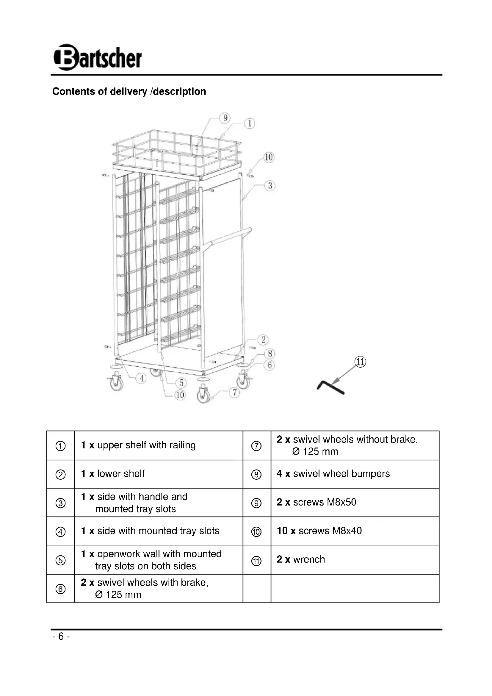
Contents of delivery /description
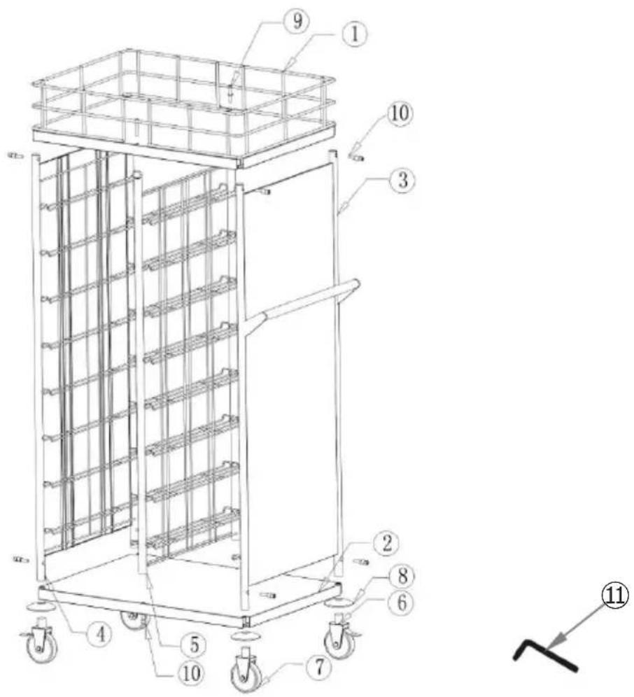
| 1 | 1 x upper shelf with railing | 7 | 2 x swivel wheels without brake, ∅ 125 mm |
| 2 | 1 x lower shelf | 8 | 4 x swivel wheel bumpers |
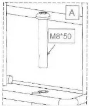
| 3 | 1 x side with handle and mounted tray slots | 9 | 2 x screws M8x50 |
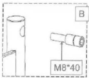
| 4 | 1 x side with mounted tray slots | 10 | 10 x screws M8x40 |
| 5 | 1 x openwork wall with mounted tray slots on both sides | 11 | 2 x wrench |
| 6 | 2 x swivel wheels with brake, ∅ 125 mm |
Assembly
- First, unpack each individual part and ensure that everything is present in the delivery. Recycle all packing material.
- Assemble the trolley based on the instructions presented below. Use the included wrench for best results.


- Begin by fixing the upper shelf with railing to the openwork wall. Lay the shelf with railing on its side and screw it into the openwork wall with 2 screws M8x50 (dia. A).

- Place the side elements in the corners of the shelf with railing, then screw the side elements into the upper shelf with railing using M8x40 screws (dia. B).
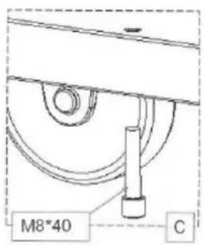
- Place the side elements in the corners of the lower shelf, then screw the lower shelf into the openwork wall followed by the side elements. Use the M8x40 screws included (dia. C).
natural_image
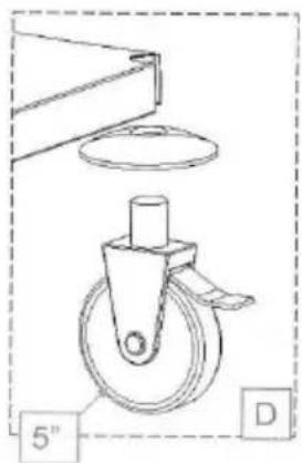
Technical line drawing of a mechanical component with a 5-inch wheel and a circular base (no text or symbols)- Place the wheel bumpers over the swivel wheels and fix them to the side, screwing the swivel wheels into the side element supports (dia. D). The wheels with brake should be mounted on opposite corners.
- Place the trolley on its wheels and check its stability.
- The trolley can be made level by screwing in/unscrewing the swivel wheels.
Tips for the user
Trays can be inserted from either side. Place the standard table trays or GN 1/1 on the railings.
To transport the trolley, use the handle at the side.
When the trolley is in the desired location, activate the brakes to prevent it from being accidentally moved.

natural_image
Exterior view of a stainless steel industrial storage unit with metal cage and tray (no visible text or symbols)Clean the trolley with a soft, moist cloth. Do not use abrasive cleaning substances that could damage the trolley's surface.
Bartscher GmbH
natural_image
Technical line drawing of a mechanical component with a 5-inch wheel and a circular base (no text or symbols)natural_image
Exterior view of a multi-level industrial storage unit with metal cage and rack panels (no visible text or symbols)natural_image
Technical line drawing of a mechanical component with a 5-inch wheel and a circular base (no text or symbols)natural_image
Interior view of a stainless steel industrial storage unit with metal cage and rack-mounted shelves (no visible text or symbols)natural_image
Technical line drawing of a mechanical component with a 5-inch wheel and a circular base (no text or symbols)natural_image
Exterior view of a stainless steel industrial storage unit with metal cage and rack-mounted shelves (no visible text or symbols)natural_image
Technical line drawing of a mechanical component with a 5-inch wheel and a circular base (no text or symbols)natural_image
Exterior view of a stainless steel industrial storage unit with metal cage and rack compartments (no visible text or symbols)BESCHRIJVING PRODUCT
natural_image
Technical line drawing of a mechanical component with a 5-inch wheel and a circular base (no text or symbols)natural_image
Exterior view of a stainless steel industrial storage unit with metal cage and rack-mounted shelves (no visible text or symbols)BESKRIVELSE AF PRODUKTET
natural_image
Technical line drawing of a mechanical component with a 5-inch angle and label D (no text or symbols beyond labels)natural_image
Exterior view of a stainless steel industrial storage unit with metal grilles and a top rack (no visible text or symbols)natural_image
Technical line drawing of a mechanical component with a 5-inch wheel and a circular base (no text or symbols)natural_image
Interior view of a stainless steel industrial storage unit with metal cage and rack-mounted shelves (no visible text or symbols)ÜRÜN TARİFİ
natural_image
Technical line drawing of a mechanical component with a 5-inch angle and label D (no text or symbols beyond labels)natural_image
Exterior view of a stainless steel industrial storage unit with metal cage and rack compartments (no visible text or symbols)natural_image
Technical line drawing of a mechanical component with a 5-inch wheel and a circular base (no text or symbols)natural_image
Exterior view of a stainless steel industrial storage unit with metal cage and rack-mounted shelves (no visible text or symbols)natural_image
Technical line drawing of a mechanical component with a 5-inch angle and label D (no text or symbols beyond labels)natural_image
Exterior view of a stainless steel industrial storage unit with metal cage and rack compartments (no text or symbols visible)| 1 | 1 x gornja polica s kukama | 7 | 2 x okretni kotač bez kočnice, ∅ 125 mm |
| 2 | 1 x donja polica | 8 | 4 x amortizer za okretne kotače |
| 3 | 1 x bočni dio s drškom i montiranim vodilicama za poslužavnik | 9 | 2 x vijak M8x50 |
| 4 | 1 x bočni dio s montiranim vodilicama za poslužavnik | 10 | 10 x vijak M8x40 |
| 5 | 1 x rešetkasta stijenka s vodilicama za poslužavnik montiranim na obje strane | 11 | 2 x imbus ključ |
| 6 | 2 x okretni kotač s kočnicom, ∅ 125 mm |
Upute za montažu
- Najprije otpakirajte pojedinačne elemente i provjerite jesu li u kompletu. Pobrinite se za reciklažu pakirnog materijala.
- Montirajte kolica za poslužavnike/posude u skladu sa donjim crtežima i uputama. Prilikom montaže koristite isporučeni imbus ključ.

- Na početku montaže gornju policu sa kukama pričvrstite na rešetkastu stijenku. Policu sa kukama postavite s bočne strane i spojite s rešetkastom stijenkom pomoću 2 vijka M8x50 (crtež A).
- Bočne elemente stavite u udubljenja na uglovima police sa kukama, a nakon toga spojite bočne dijelove i gornju policu s kukama pomoću vijaka M8x40 (crtež B).

- Na početku bočne elemente stavite u udubljenja na uglovima donje police i prvo sastavite donju policu i rešetkastu stijenku, a nakon toga spojite bočne elemente. Upotrijebite isporučene vijke M8x40 (crtež C).

natural_image
Technical line drawing of a mechanical component with a 5-inch wheel and a circular base (no text or symbols)natural_image
Exterior view of a stainless steel industrial storage unit with metal cage and rack-mounted shelves (no visible text or symbols)TERMÉK LEÍRÁS
natural_image
Technical line drawing of a mechanical component with a 5-inch angle and label D (no text or symbols beyond labels)natural_image
Exterior view of a stainless steel industrial storage unit with metal cage and rack compartments (no text or symbols visible)natural_image
Technical line drawing of a mechanical component with a 5-inch wheel and a circular base (no text or symbols)natural_image
Exterior view of a stainless steel industrial storage unit with metal cage and rack-mounted shelves (no visible text or symbols)

Brand : BARTSCHER
Model : TT1600
Category : Transport cart