CenterScanner Plus - Drill Laserliner - Free user manual and instructions
Find the device manual for free CenterScanner Plus Laserliner in PDF.
| Product Type | Drilling Point Locator Transmitter/Receiver Kit |
| Brand | Laserliner |
| Model | CenterScanner Plus |
| Category | Drilling Accessory |
| Composition | Transmitter TX and Receiver RECV |
| Dimensions (L x H x W) | 75 x 172 x 28 mm (each unit) |
| Weight (batteries included) | Transmitter: 200 g, Receiver: 210 g |
| Power Supply | 3 alkaline 1.5 V AAA batteries per unit |
| Battery Life | Transmitter: 12 h, Receiver: 20 h |
| Main Functions | Drilling point location, metal detection, voltage detection (230 V AC) |
| Indicators | Positioning LEDs (arrows and green squares), metal/voltage detection LEDs, audible signal |
| Display | 3-digit 7-segment LCD for drilling depth |
| Measuring Range (position) | 2 to 150 cm (with LED indicators); depth indicator up to 200 cm |
| Accuracy | Typ. 3% of measurement depth |
| Metal and Voltage Detection | Detects ferrous/non-ferrous metals and live cables in non-metallic materials |
| Operating Conditions | -30 °C to 40 °C (receiver) / -20 °C to 40 °C (transmitter), max. 85% RH, non-condensing |
| Storage | -20 °C to 60 °C, max. 85% RH |
| Radio Interface | 433.95 MHz, power < -13 dBm |
| Standards | RED Directive 2014/53/EU, declaration of conformity available at laserliner.com |
| Care and Cleaning | Clean with a slightly damp cloth, no solvents. Remove batteries before prolonged storage. |
| Safety Instructions | Do not use near electrical installations without safety measures; verify absence of voltage before drilling; keep out of reach of children. |
| Spare Parts and Repairability | Replaceable batteries (AAA); no additional detachable parts. Manufacturer repair recommended. |
| Warranty and Support | Refer to the provided warranty booklet; information at laserliner.com |
Frequently Asked Questions - CenterScanner Plus Laserliner
User questions about CenterScanner Plus Laserliner
0 question about this device. Answer the ones you know or ask your own.
Ask a new question about this device
Download the instructions for your Drill in PDF format for free! Find your manual CenterScanner Plus - Laserliner and take your electronic device back in hand. On this page are published all the documents necessary for the use of your device. CenterScanner Plus by Laserliner.
USER MANUAL CenterScanner Plus Laserliner
text_image
Laserliner® CenterScanner Plus TX 83.9 cm Laserliner® CenterScanner Plus RECV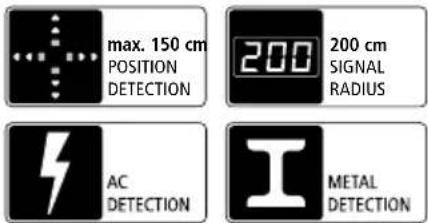
text_image
max. 150 cm POSITION DETECTION 200 200 cm SIGNAL RADIUS AC DETECTION METAL DETECTIONLaserliner®
!
natural_image
Interior view of a battery pack showing internal components and a close-up of the main casing (no visible text or symbols)natural_image
Illustration of a wall-mounted smart lock with a control panel, set against a brick wall background (no text or symbols)
natural_image
Illustration of a wall-mounted device with sound waves and directional arrows, next to a brick wall (no text or symbols)
natural_image
Exterior view of a wall-mounted security camera mounted on a brick wall (no text or symbols visible)natural_image
Illustration of a speaker emitting sound waves near a wall-mounted device, with no visible text or symbols.
natural_image
Exterior view of a wall-mounted device with a circular sensor mounted on a vertical panel (no visible text or symbols)
text_image
Safety warning sign and contact icon for a wall-mounted phone, showing hazard symbol, speaker, and contact detailsnatural_image
Diagram showing a device mounted on a beam with alignment markers, no visible text or symbols
text_image
d inatural_image
Abstract geometric composition with pixelated texture and geometric shapes (no text or symbols)
natural_image
Diagram showing a tool interacting with a brick wall and two devices (no text or symbols)Completely read through the operating instructions, the "Warranty and Additional Information" booklet as well as the latest information under the internet link at the end of these instructions. Follow the instructions they contain. This document must be kept in a safe place and passed on together with the device.
Function/Application
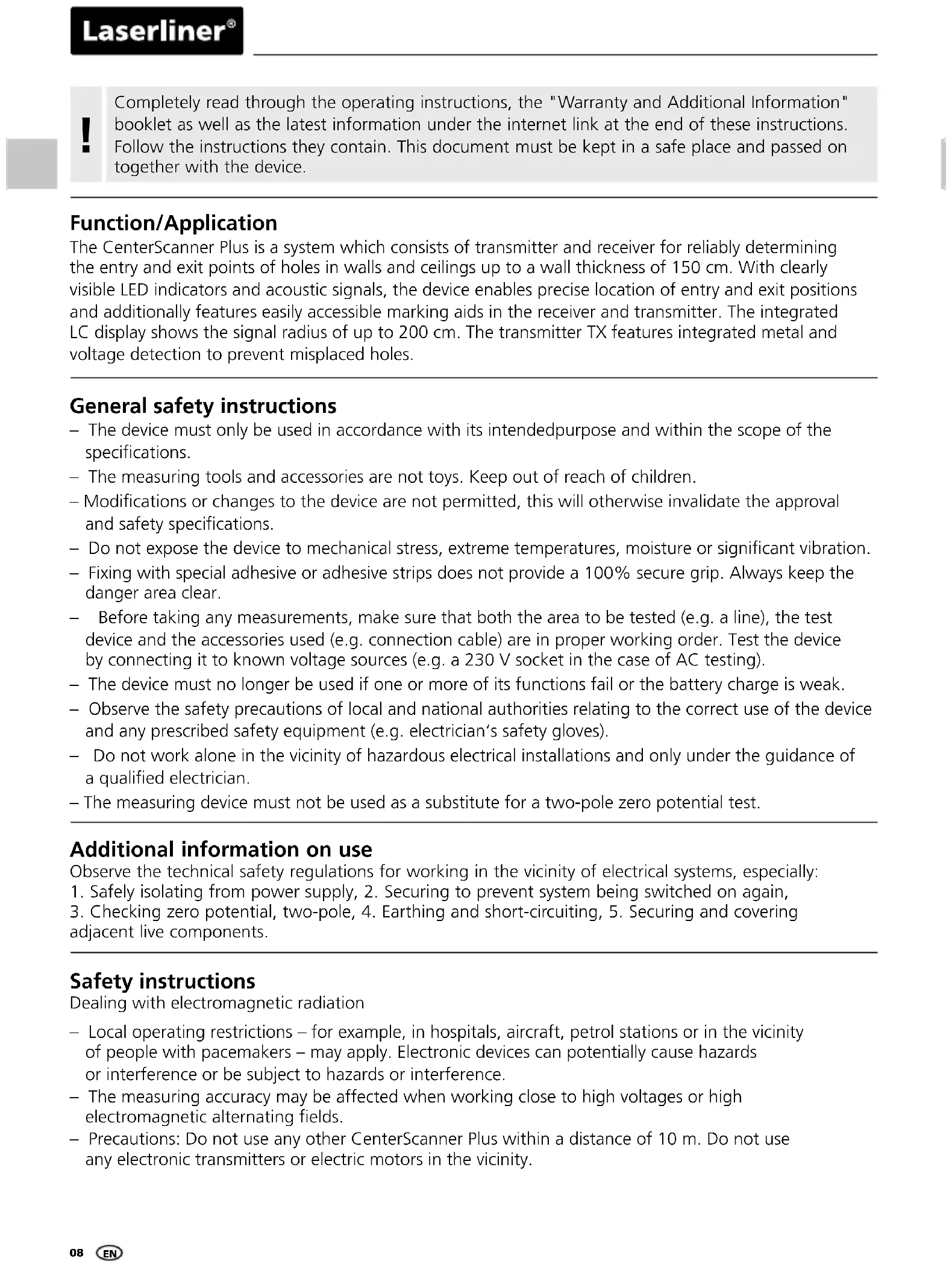
The CenterScanner Plus is a system which consists of transmitter and receiver for reliably determining the entry and exit points of holes in walls and ceilings up to a wall thickness of 150 cm. With clearly visible LED indicators and acoustic signals, the device enables precise location of entry and exit positions and additionally features easily accessible marking aids in the receiver and transmitter. The integrated LC display shows the signal radius of up to 200 cm. The transmitter TX features integrated metal and voltage detection to prevent misplaced holes.
General safety instructions
- The device must only be used in accordance with its intended purpose and within the scope of the specifications.
- The measuring tools and accessories are not toys. Keep out of reach of children.
- Modifications or changes to the device are not permitted, this will otherwise invalidate the approval and safety specifications.
- Do not expose the device to mechanical stress, extreme temperatures, moisture or significant vibration.
- Fixing with special adhesive or adhesive strips does not provide a 100% secure grip. Always keep the danger area clear.
Before taking any measurements, make sure that both the area to be tested (e.g. a line), the test device and the accessories used (e.g. connection cable) are in proper working order. Test the device by connecting it to known voltage sources (e.g. a 230 V socket in the case of AC testing). - The device must no longer be used if one or more of its functions fail or the battery charge is weak.
- Observe the safety precautions of local and national authorities relating to the correct use of the device and any prescribed safety equipment (e.g. electrician's safety gloves).
- Do not work alone in the vicinity of hazardous electrical installations and only under the guidance of a qualified electrician.
- The measuring device must not be used as a substitute for a two-pole zero potential test.
Additional information on use
Observe the technical safety regulations for working in the vicinity of electrical systems, especially:
- Safely isolating from power supply, 2. Securing to prevent system being switched on again,
- Checking zero potential, two-pole, 4. Earthing and short-circuiting, 5. Securing and covering adjacent live components.
Safety instructions
Dealing with electromagnetic radiation
- Local operating restrictions – for example, in hospitals, aircraft, petrol stations or in the vicinity of people with pacemakers – may apply. Electronic devices can potentially cause hazards or interference or be subject to hazards or interference.
- The measuring accuracy may be affected when working close to high voltages or high electromagnetic alternating fields.
- Precautions: Do not use any other CenterScanner Plus within a distance of 10m . Do not use any electronic transmitters or electric motors in the vicinity.
Safety instructions
Dealing with RF radiation
- The measuring device is equipped with a wireless interface.
- The measuring device complies with electromagnetic compatibility regulations and limit values in accordance with RED Directive 2014/53/EU.
- Umarex GmbH & Co. KG hereby declares that the CenterScanner Plus radio equipment complies with the essential requirements and other provisions of the European Radio Equipment Directive 2014/53/EU (RED). The EU Declaration of Conformity can be found in its entirety at the following address:
http://laserliner.com/info?an=cescapl
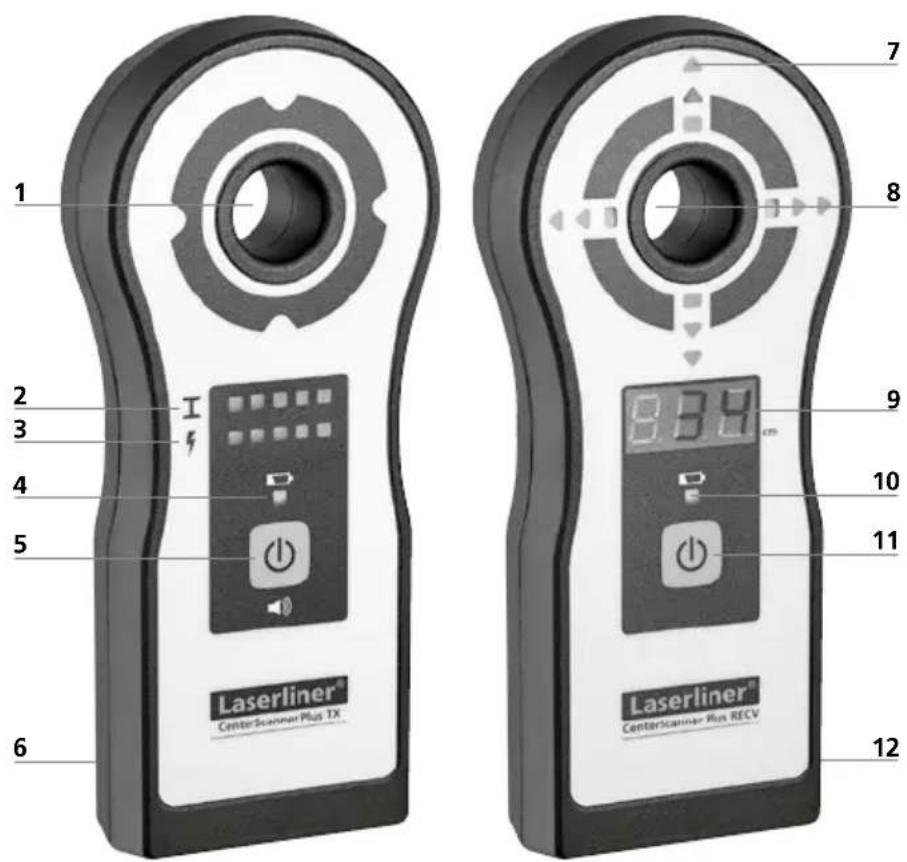
Transmitter TX Receiver RECV
text_image
1 2 3 4 5 6 Laserliner® CenterScanmer Plus TX 7 8 9 10 11 12 8.8.9 cm Laserliner® CenterScanmer Run RECVTransmitter TX
1 Marking aid aperture
2 LED indicators for metal detection
3 LED indicators for voltage detection
4 LED battery charge indicator
5 Device ON/OFF / sound ON/OFF
6 Battery compartment (rear)
Receiver RECV
7 LED indicators for positioning
8 Marking aid aperture
9 LC display for drilling depth
10 LED battery charge indicator
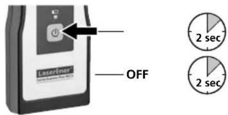
11 Device ON/OFF
12 Battery compartment (rear)
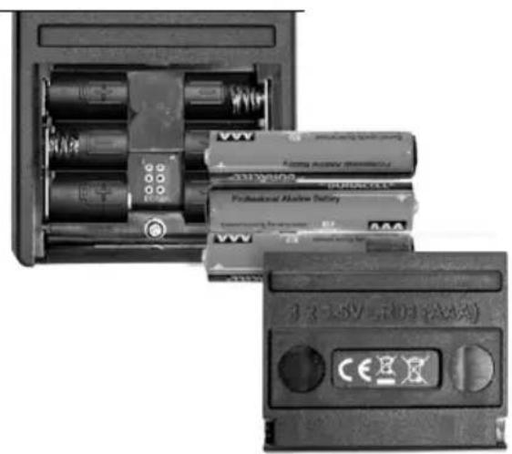
1 Inserting batteries
Transmitter TX and Receiver RECV
Open the battery compartment and insert batteries according to the symbols. Be sure to pay attention to polarity.
natural_image
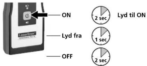
Interior view of a battery pack showing internal components and a close-up of the battery casing (no visible text or symbols)2 Device ON/OFF / sound ON/OFF
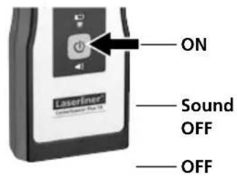
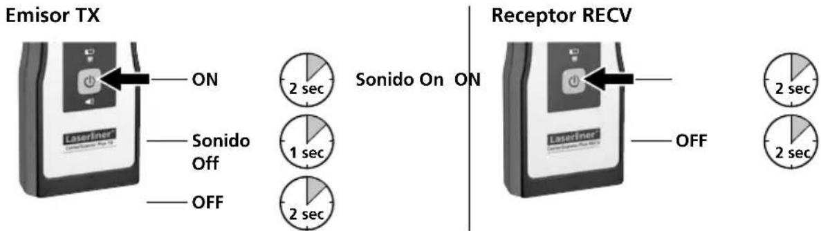
Transmitter TX
text_image
ON Laserfiner Sound OFF OFF
Sound ON ON


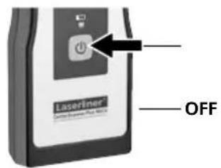
Receiver RECV
text_image
Laserliner OFF

B To determine drilling position
natural_image
Illustration of a wall-mounted digital camera with a circular button, set against a brick wall background (no text or symbols)
natural_image
Illustration of a door lock mechanism with sound waves and directional arrows, set against a brick wall (no text or symbols)
natural_image
Exterior view of a wall-mounted smart lock with a brick wall and a black square marker (no text or symbols visible)-
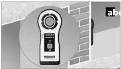
With special adhesive on the back, securely position the transmitter TX at the required drilling point on the wall or ceiling (see Fig. a).
-
Switch on transmitter TX and receiver RECV.
-
Move the receiver RECV on the other side of the wall/ceiling (see Fig. b). With red arrows, the positioning LEDs (7) show the direction of movement. Green squares show that the positions of the transmitter TX and receiver RECV are aligned.
-
Positioning is correct when the four green squares light. After marking the drilling point (see Fig. c), remove the devices from the wall/ceiling and drill the hole.
Remove the devices from the wall/ceiling before drilling. Drilling through the marking aid aperture is at your own risk.
To determine drilling depth >150 cm
text_image
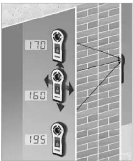
170 160 195The positioning LEDs (7) are suitable for determining drilling depths of up to 150 cm.
At depths >150 cm, the drilling point can be set by determining the minimum drilling depth with the aid of the LC display (9).
To do so, move the receiver over the wall on the X and Y axis and mark the positions on reaching the minimum drilling depth shown on the display from all four directions (right, left, top, bottom to imaginary centre point).
The four markers are on a coordinate cross (X/Y-axis) with its centre point corresponding to the required drilling position.
4 Metal detection
The tool is able to detect hidden metal in all non-metallic materials, e.g. brick, concrete, screed, wood, plaster fibreboard, gas concrete, ceramic and mineral building materials.
natural_image
Illustration of a speaker with sound waves and a digital camera, connected to a faucet (no text or symbols)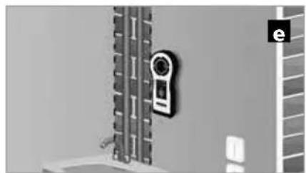
natural_image
Exterior view of a wall-mounted security camera mounted on a vertical panel (no visible text or symbols)
-
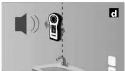
Switch on device and slowly move it over the surface (see Fig. d). The LED indicators (2) show if there is metal close by. Mark the spot when all indicators are on.
-
Repeat step 1 (see Fig. e).
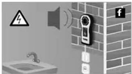
5 Voltage detection
For localising live wires directly beneath the plaster or behind wooden panels and other non-metallic panelling. It is not possible to detect live wires in dry walls with metal studs.
text_image
Diagram showing a wall-mounted device with warning symbol, speaker, and contact details, alongside a faucet and Facebook icon.Switch on device and slowly move it over the surface (see Fig. f). The LED indicators (3) show if there is a live cable close by.
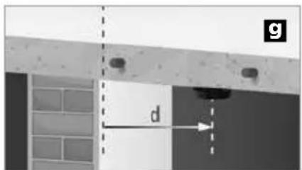
6 Offset measurement
text_image
g d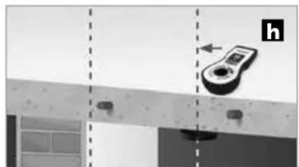
natural_image
Diagram showing a device mounted on a beam with alignment markers, no visible text or symbols
text_image
d i- Move the transmitter TX in an area where there is no metal and measure the distance from the transmitter TX to the required drilling point (see Fig. g).
- Determine the position of the transmitter TX with the receiver RECV on the other side (see Fig. h).
- Transfer the measured distance (step 1) in the direction of the required drilling point (see Fig. i).
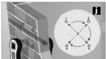
7 Multipoint measurement
text_image
0 0 0 1 2 3 4 j
text_image
1 2 3 4 k- Mark at least two, preferably four, reference points at precisely the same distance from the intended drilling point (see Fig. j).
- The corrected drilling point is located at the geometric centre point of the reference points (see Fig. k).
Tip: Interference caused by metal can prevent the drilling point being located. In these rare cases, the four square LED indicators will not light up at any point. The tolerance of the receiver RECV can be increased by briefly pressing the ON/OFF button (11). The setting is confirmed by a longer acoustic signal. The device reverts to normal operating mode by pressing the ON/OFF button (11) again or switching off the device.

Operation in increased tolerance mode slightly reduces the accuracy of drilling point positioning.
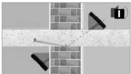
8 Hoekmetingen
If accurate positioning and alignment are not possible, for example when drilling in corners, the device can be aligned using two identical wedge-shaped supports. The angles of the wedges must match the required drilling angle.
natural_image
Abstract geometric composition with shaded regions and geometric shapes (no text or symbols)
natural_image
Diagram showing a tool interacting with a brick wall and a device, no text or symbols present- Place a wedge under the transmitter TX and under the receiver RECV and make sure that the centre line of both devices points in the direction of the required drilling point (see Fig. I).
- Drill the hole (see Fig. m).

Different wedge angles can result in misplaced holes. Always use identical wedges.
Information on maintenance and care
Clean all components with a damp cloth and do not use cleaning agents, scouring agents and solvents. Remove the battery(ies) before storing for longer periods. Store the device in a clean and dry place.
| Technical data (Technical revisions reserved. 10.17) | |
| CenterScanner Plus RECV | |
| Indicators 13 LEDs, acoustic warning signal | |
| LED display 3 x 7 segment | |
| Measuring depth | Positioning: 2 - 150 cm wall thicknessDepth display: 2 - 200 cm drilling depth |
| Accuracy Typically 3% of measured depth | |
| Operating time approx. 20 h | |
| Operating conditions | -30°C ... 40°C, Max. humidity 85% rH, no condensation,Max. working altitude 2000 m above sea level |
| Storage conditions -20°C ... 60°C, Max. humidity 85% rH | |
| Radio module operating data | Frequency band 1: ISM band 433.95 MHzBandwidth: 0.05 MHzReceiver category: 3 |
| Power supply 3x 1.5 V alkaline battery (type | AAA) |
| Dimensions (W x H x D) 75 x 172 x 28 mm | |
| Weight (incl. batteries) 210 g | |
| CenterScanner Plus TX | |
| Indicators 11 LEDs, acoustic warning signal | |
| Operating time approx. 12 h | |
| Operating conditions | -20°C ... 40°C, Max. humidity 85% rH, no condensation,Max. working altitude 2000 m above sea level |
| Storage conditions -20°C ... 60°C, Max. humidity 85% rH | |
| Radio module operating data | Frequency band 1: ISM band 433.95 MHzTransmit power: < -13 dBmWBandwidth: 0.05 Mhz |
| Power supply 3x 1.5 V alkaline battery (type | AAA) |
| Dimensions (W x H x D) 75 x 172 x 28 mm | |
| Weight (incl. batteries) 200 g | |
EU directives and disposal
This device complies with all necessary standards
for the free movement of goods within the EU.
This product is an electric device and must be collected separately for disposal according to the European
Directive on waste electrical and electronic equipment.
Further safety and supplementary notices at:
http://laserliner.com/info?an=cescapl
text_image
CE × ×!
natural_image
Interior view of a battery pack showing internal components and battery modules (no readable text or symbols)natural_image
Illustration of a wall-mounted smart lock with control panel, set against brick wall background (no text or symbols)
natural_image
Illustration of a wall-mounted device with sound waves and directional arrows, next to a brick wall (no text or symbols)
natural_image
Exterior view of a wall-mounted security camera mounted on a brick wall (no text or symbols visible)natural_image
Illustration of a speaker emitting sound waves near a wall-mounted device, with no visible text or symbols.
natural_image
Exterior view of a wall-mounted security camera mounted on a grid-patterned surface (no text or symbols visible)
text_image
Diagram showing a wall-mounted phone with sound waves, warning symbol, and a water tap, alongside a Facebook icon.natural_image
Exterior view of a building corner with structural beams and a dimension label 'd' (no text or symbols beyond the label)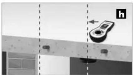
natural_image
Diagram showing a device mounted on a beam with alignment lines, no visible text or symbols
text_image
d itext_image
Diagram showing a mechanical linkage system with labeled components and a circular diagram illustrating rotational motion.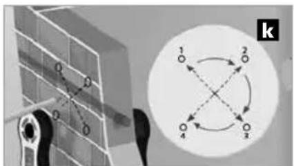
text_image
O O O 1 2 4 3 knatural_image
Abstract geometric composition with shaded regions and a speaker icon (no text or symbols)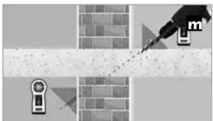
natural_image
Illustration of a pipette tiping a textured surface with a magnifying glass and a small device icon (no text or symbols)natural_image
Interior view of a battery pack showing internal components and a close-up of the next battery (no visible text or symbols)2 Apparat til/fra / Lyd til/fra
Sender TX
text_image
ON Lyd fra OFF 2 sec 1 sec 2 sec Lyd til ONModtager RECV
text_image
LaserTimer OFF 2 sec 2 secnatural_image
Illustration of a wall-mounted smart lock with control panel and display (no text or symbols)
natural_image
Illustration of a wall-mounted device with sound waves and directional arrows, next to a brick wall (no text or symbols)
natural_image
Exterior view of a wall-mounted security camera mounted on a brick wall (no text or symbols visible)natural_image
Illustration of a speaker emitting sound waves near a wall-mounted device, with no visible text or symbols.
natural_image
Exterior view of a wall-mounted device mounted on a grid-patterned surface (no visible text or symbols)
text_image
Diagram showing a bathroom with a speaker, warning symbol, and a wall-mounted device connected to a coffee shop, alongside a 'f' icon.natural_image
Diagram showing a device mounted on a wall with dashed alignment lines, no visible text or symbols
text_image
d inatural_image
Abstract geometric composition with shaded regions and geometric shapes (no text or symbols)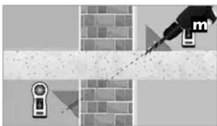
natural_image
Diagram showing a tool interacting with a brick wall and a sensor device, no text or symbols presenttext_image
CE RECOLOGY!
natural_image
Interior view of a battery pack with multiple batteries and a 3.2 kV power cord (no visible text or symbols)natural_image
Three-panel illustration showing a wall-mounted device with a speaker, emitting sound waves, and a close-up of the device on a brick wall (no text or symbols)natural_image
Illustration of a speaker emitting sound waves near a wall-mounted device, with no visible text or symbols.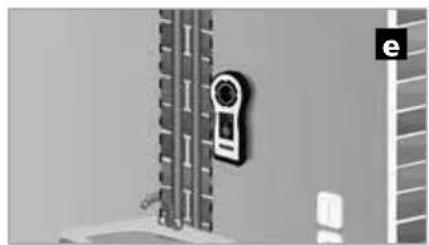
natural_image
Exterior view of a wall-mounted device mounted on a vertical panel, with no visible text or symbols.
text_image
Safety warning sign and digital contact icons for a security camera, including a warning symbol, speaker, and contact details.natural_image
Diagram showing a device mounted on a beam with alignment markers, no visible text or symbols
text_image
d inatural_image
Abstract geometric composition with brick wall, diagonal line, and triangular shapes (no text or symbols)
natural_image
Illustration of a hand using a tool to mark a cross-shaped object, with no visible text or symbols.natural_image
Interior view of a battery pack showing internal components and a separate card with CE logo (no readable text or symbols)2 Aparato On/Off Sonido On/Off
text_image
Emisor TX ON Sonido On ON Laseriner Sonido Off OFF 2 sec 1 sec 2 sec Receptor RECV 2 sec OFF 2 secnatural_image
Illustration of a remote control device with a circular button and a grid, set against a brick wall background (no text or symbols)
natural_image
Illustration of a wall-mounted device with sound waves and directional arrows, next to a brick wall (no text or symbols)
natural_image
Exterior view of a wall-mounted security camera mounted on a brick wall (no text or symbols visible)natural_image
Illustration of a speaker with sound waves and a digital camera, connected to a sink (no text or symbols)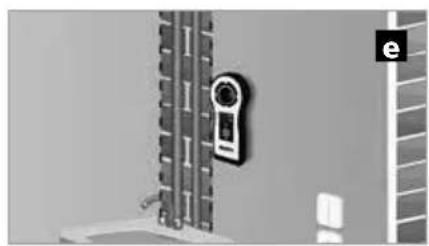
natural_image
Exterior view of a wall-mounted door with a close-up of the door handle (no text or symbols visible)
text_image
Diagram showing a bathroom with a speaker, warning symbol, and social media icons (Facebook and Twitter) near a wall-mounted door.natural_image
Diagram showing a device mounted on a beam with alignment markers, no visible text or symbols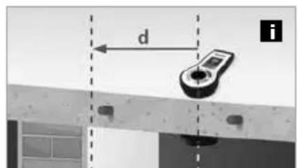
text_image
d itext_image
Diagram showing a mechanical linkage system with labeled components and a circular diagram with four numbered nodes connected by dashed arrows.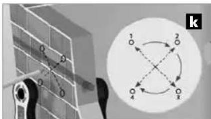
text_image
O D O D 1 2 O 4 3 knatural_image
Abstract geometric composition with pixelated texture and geometric shapes (no text or symbols)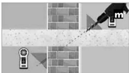
natural_image
Diagram showing a tool interacting with a brick wall and a handheld device, no text or symbols presentnatural_image
Interior view of an electronic device showing battery pack, charging case, and internal components (no readable text or symbols)natural_image
Illustration of a wall-mounted smart lock with control panel and display, set against brick wall background (no text or symbols)
natural_image
Illustration of a mounted device with sound waves and directional arrows, set against a brick wall background (no text or symbols)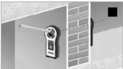
natural_image
Exterior view of a wall-mounted digital camera with a brick wall and a black square marker (no text or symbols visible)natural_image
Illustration of a speaker with sound waves and a digital camera, connected to a sink (no text or symbols)
natural_image
Exterior view of a wall-mounted door with a close-up of the door handle (no text or symbols visible)
text_image
Safety warning sign and social media icons for a bathroom, including a speaker, sound waves, and a wall-mounted device.natural_image
Diagram showing a device mounted on a beam with alignment markers, no visible text or symbols
text_image
d inatural_image
Abstract geometric composition with brick wall, diagonal lines, and small shapes (no text or symbols)
natural_image
Diagram showing a dropper tip interacting with a textured surface, with no visible text or symbolstext_image
CE RECOLOGY RECOLOGY RECOLOGY!
natural_image
Interior view of a battery pack showing internal components and battery modules (no readable text or symbols)natural_image
Illustration of a smart home control device with a circular button and display screen, set against a brick wall background (no text or symbols)
natural_image
Illustration of a wall-mounted device with sound waves and directional arrows, next to a brick wall (no text or symbols)
natural_image
Exterior view of a wall-mounted security camera mounted on a brick wall (no text or symbols visible)natural_image
Illustration of a speaker emitting sound waves next to a digital camera, with no visible text or symbols
natural_image
Exterior view of a wall-mounted device with a close-up corner, no visible text or symbols
text_image
Diagram showing a bathroom with a speaker, warning symbol, and a wall-mounted device labeled 'f'natural_image
Diagram showing a device mounted on a beam with alignment markers, no visible text or symbols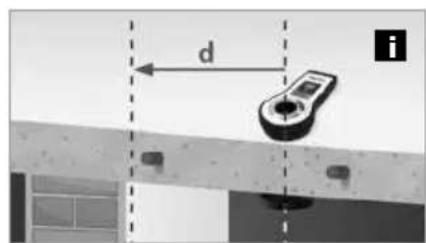
text_image
d inatural_image
Abstract geometric composition with brick wall, diagonal lines, and small shapes (no text or symbols)
natural_image
Diagram showing a tool interacting with a textured surface and a device, no text or symbols presenttext_image
CE RECOLOGY RECOLOGY RECOLOGY!
natural_image
Interior view of a battery pack with internal components and a separate CD-ROM card showing model number 3-3 A5V, no readable text or symbols beyond branding.natural_image
Illustration of a smart home control device with a circular button and display screen, set against a brick wall background (no text or symbols)
natural_image
Illustration of a door with sound waves and directional arrows, next to a brick wall (no text or symbols)
natural_image
Exterior view of a wall-mounted security camera mounted on a brick wall (no text or symbols visible)natural_image
Illustration of a speaker emitting sound waves near a wall-mounted device, with no visible text or symbols.
natural_image
Exterior view of a wall-mounted security camera mounted on a grid-patterned surface (no text or symbols visible)
text_image
Diagram illustrating a bathroom security system with sound waves, a speaker, and a wall-mounted device connected to a sink.natural_image
Diagram showing a device mounted on a wall with dashed alignment lines, no visible text or symbols
text_image
d inatural_image
Abstract geometric composition with brick wall, diagonal lines, and small shapes (no text or symbols)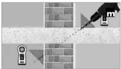
natural_image
Illustration of a paintbrush applying paint to a brick wall, with no visible text or symbolsnatural_image
Interior view of a battery pack showing internal components and a close-up of the main casing (no visible text or symbols)natural_image
Illustration of a smart home control device with a circular button and display screen, set against a brick wall background (no text or symbols)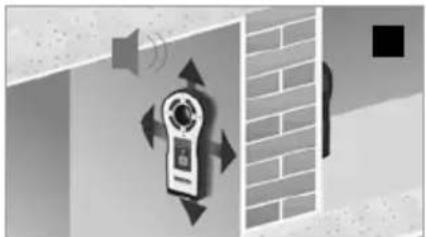
natural_image
Illustration of a wall-mounted device with sound waves and directional arrows, next to a brick wall (no text or symbols)
natural_image
Exterior view of a wall-mounted digital camera with a brick wall and a black square marker (no text or symbols visible)natural_image
Illustration of a speaker emitting sound waves next to a digital camera, with no visible text or symbols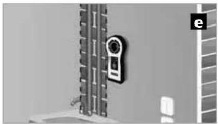
natural_image
Exterior view of a wall-mounted device with a camera and adjacent storage unit (no visible text or symbols)
text_image
Safety warning symbol and social media icons for a wall-mounted phone, including a warning sign, speaker, and Facebook iconnatural_image
Diagram showing a device mounted on a beam with alignment markers, no visible text or symbols
text_image
d inatural_image
Abstract geometric composition with shaded regions and a speaker icon (no text or symbols)
natural_image
Diagram showing a tool interacting with a brick wall and a device, no text or symbols presentnatural_image
Interior view of a battery pack showing internal components and a separate card with CE logo (no readable text or symbols)2 Apparat På/Av Signalton På/Av
Sändare TX
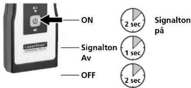
text_image
ON Signalton Av OFF 2 sec Signalton på 1 sec 2 secMottagare RECV
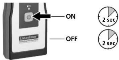
text_image
ON OFF Laserliner 2 sec 2 secnatural_image
Illustration of a remote control device with a circular button and a small screen, set against a brick wall background (no text or symbols)
natural_image
Illustration of a wall-mounted device with sound waves and directional arrows, next to a brick wall (no text or symbols)
natural_image
Exterior view of a wall-mounted security camera mounted on a brick wall (no text or symbols visible)natural_image
Illustration of a speaker emitting sound waves near a wall-mounted device, with no visible text or symbols.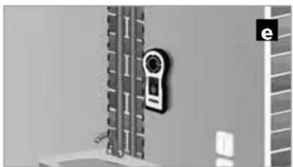
natural_image
Exterior view of a wall-mounted device with a circular sensor mounted on a vertical panel (no visible text or symbols)
text_image
Safety warning symbol and social media icons for a wall-mounted phone, including a warning sign, speaker, and Facebook iconnatural_image
Diagram showing a device mounted on a beam with alignment lines, no visible text or symbols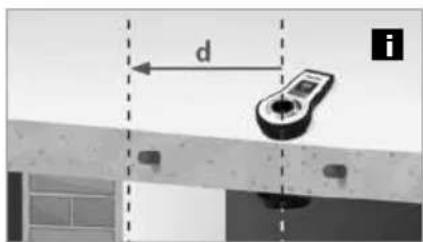
text_image
d itext_image
Diagram showing a mechanical linkage system with labeled components and a circular diagram with four directional arrows indicating rotational or bidirectional motion.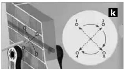
text_image
k 1 2 3 4natural_image
Abstract geometric composition with brick wall, diagonal line, and triangular shapes (no text or symbols)
natural_image
Illustration of a mechanical tool interacting with a brick wall and a sensor device (no text or symbols)natural_image
Illustration of a wall-mounted device and two hanging devices against a brick wall (no text or symbols)SERVICE


Umarex GmbH & Co. KG
-Laserliner-