
AGC 18 - Grinder FESTOOL - Free user manual and instructions
Find the device manual for free AGC 18 FESTOOL in PDF.

| Product type | Cordless angle grinder (grinder) |
| Brand | Festool |
| Model | AGC 18 |
| Rated voltage | 18 V DC |
| Speed (no load) | 4500 - 8500 rpm (6 adjustable levels) |
| Max abrasive tool diameter | 125 mm |
| Permissible tool thickness | 1.0 - 6.0 mm |
| Spindle thread | M14 |
| Weight (per EPTA 01:2014) | 2.7 kg |
| Compatible battery | Festool BP 18 Li (3.1 Ah, 4.0 Ah, 5.2 Ah, 6.2 Ah) |
| Sound pressure level LpA | 86 dB(A) (K=3 dB) |
| Sound power level LwA | 97 dB(A) (K=3 dB) |
| Vibration (sanding) | 5.0 m/s² (K=2 m/s²) |
| Vibration (cutting) | ≤2.5 m/s² (K=2 m/s²) |
| Main functions | Cutting, light sanding, wire brushing, deburring (metals and minerals, without liquid) |
| Safety features | Soft start, speed regulator, constant speed, kickback protection, restart protection, overheat protection |
| Supplied accessories | Protective hood, VIBRASTOP additional handle, quick-release nut |
| Maintenance and cleaning | Clean ventilation slots with dry, oil-free compressed air after each use |
| Required protective equipment | Hearing protection, eye protection, respiratory protection (P2), gloves, sturdy shoes |
| Standards | CE, EN 60745, EN 12413, EN 13236, EN 1083 |
Frequently Asked Questions - AGC 18 FESTOOL
User questions about AGC 18 FESTOOL
0 question about this device. Answer the ones you know or ask your own.
Ask a new question about this device
Download the instructions for your Grinder in PDF format for free! Find your manual AGC 18 - FESTOOL and take your electronic device back in hand. On this page are published all the documents necessary for the use of your device. AGC 18 by FESTOOL.
USER MANUAL AGC 18 FESTOOL
natural_image
Exterior view of a PASTOL angle grinder with black and white body (no text or symbols visible)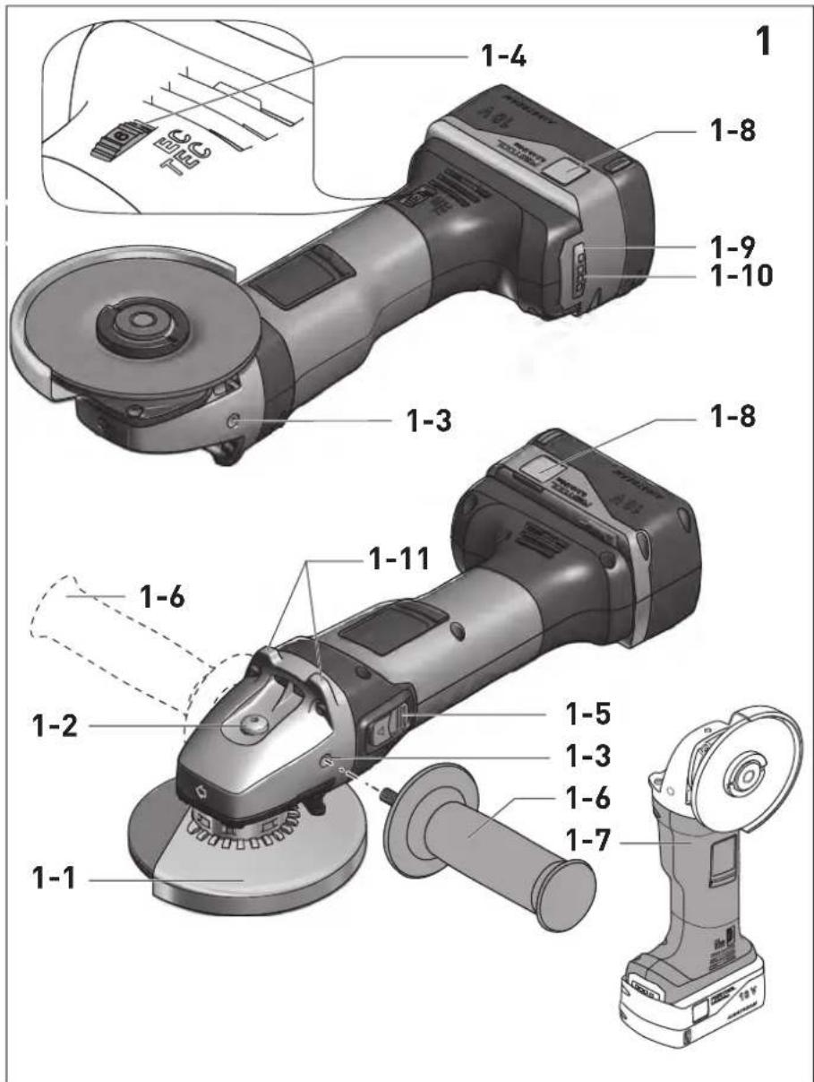
Declaration of Conformity
We as the manufacturer Festool GmbH, Wertstraße 20, 73240 Wendlingen, Germany declare under our sole responsibility that the product(s):
Designation:
Designation of Type(s):
Serial number(s) 11:
Cordless angle grinder
AGC 18
204079
fulfills all the relevant provisions of the following UK Regulations:
S.I. 2008/1597
S.I. 2016/1091 ^4
S.I. 2017/1206 ^3
S.I. 2012/3032
Supply of Machinery (Safety) Regulations 2008
Electromagnetic Compatibility Regulations 2016
Radio Equipment Regulations 2017
Restriction of the Use of Certain Hazardous Substances in Electrical and Electronic Equipment Regulations 2012
and are manufactured in accordance with the following designated standards:
• BS EN 60745-1:2009 + A11:2010
• BS EN 60745-2-3:2011+A13:2015
• BS EN 55014-1:2017 ^2)
• BS EN 55014-2:2015 ^2)
• EN 300 328:2016 V2.1.1 ^3)
• EN 301 489-1:2017 V2.1.1 ^3)
• EN 301 489-17:2017 V3.1.1 ^3)
• BS EN IEC 63000:2018
1) in the specified serial number range (S-Nr.) from 400000000 - 499999999
21 valid in combination with battery pack BP 18 Li 5,2 AS, BP 18 Li 6,2 AS, BP 18 Li 3,1 C, BP 18 Li 4,0 HPC-AS
3) valid in combination with Bluetooth® battery pack BP 18 Li 5,2 ASI, BP 18 Li 6,2 ASI, BP 18 Li 3,1 Cl, BP 18 Li 4,0 HPC-ASI

Place and date of declaration: Wendlingen, 31.03.2021
Signed on behalf of and in name of Festool GmbH

i.v. Q. Brandt
Ralf Brandt
Head of Productconformity
Akku-Winkelschleifer Cordless angle grinder Meuleuse d'angle sans fil
Seriennummer ^1) Serial number ^1) N° de série ^1) (T-Nr.)
AGC 18 204079
de EU-Konformitätserklärung. Wir erklären in alleiniger Verantwortung, dass dieses Produkt mit allen relevanten Anforderungen folgender EU-Richtlinien übereinstimmt, und folgende Normen oder normative Dokumente zugrunde gelegt wurden:
en EU Declaration of Conformity. We declare under sole responsibility that this product complies with all the relevant requirements in the following EU Directives, and following standards and normative documents were applied:
fr Déclaration de conformité de l'UE. Nous déclarons, sous notre seule responsabilité, que ce produit satisfait à toutes les exigences pertinentes des directives UE suivantes et repose sur les normes ou documents normatifs suivants :
es Declaración UE de conformidad. Declaramos bajo nuestra responsabilidad que este producto cumple todos los requisitos relevantes de las siguientes directivas de la UE y que se han tomado como base las siguientes normas o documentos normativos:
it Dichiarazione di conformità UE. Dichiariamo sotto nostra unica responsabilità che il presente prodotto sia conforme a tutti i requisiti di rilevanza definiti dalle seguenti Direttive UE e che siano stati applicati le seguenti norme o i seguenti documenti normativi:
nl EU-conformiteitsverklaring. Wij verklaren en stellen ons ervoor verantwoordelijk dat dit product volledig voldoet aan alle volgende EU-richtlijnen en volgende normen of normatieve documenten daaraan ten grondslag gelegd werden:
SV EU-försäkran om överensstämmelse. Vi för- klarar på eget ansvar att denna produkt uppfyller alla relevanta krav enligt följande EU-direktiv och baseras på följande normer eller normgivande dokument:
fi EU-vaatimustenmukaisuusvakuutus. Vakuutamme yksinomaisella vastuulla, että tämä tuote täyttää seuraavien EU-direktiivien kaikki olennaiset vaatimukset ja se on seuraavien standardien tai standardiasia-kirjojen mukainen:
da EU-overensstemmelseserklæring. Vi erklærer med eneansvar, at dette produkt er i overensstemmelse med alle relevante krav i følgende EU-direktiver, og at følgende standarder eller normative dokumenter danner grundlag for det:
nb EU-samsvarserklæring. Vi erklærer under eneansvar at dette produktet oppfyller alle relevante krav i følgende EU-direktiver og at følgende standarder eller normative dokumenter er blitt lagt til grunn:
pt Declaração de conformidade UE. Sob nossa inteira responsabilidade, declaramos que este produto
Head of Product Development
Ralf Brandt
Head of Product Conformity
valid in combination with battery pack/
valid in combination with Bluetooth® battery pack/
1 Symbols....18
2 Safety warnings....18
3 Intended use 22
4 Technical data.... 22
5 Parts of the machine....22
6 Commissioning....23
7 Battery pack.... 23
8 Settings....23
9 Working with the electric power tool.....25
10 Acoustic warning signal....25
11 Accessories.... 26
12 Service and maintenance....26
13 Environment....26
14 General information....26
1 Symbols

Warning of general danger

Warning of electric shock

Read the operating instructions and safety instructions.

Wear ear protection.

Wear protective gloves.

Wear a dust mask.

Wear protective goggles.

Wear sturdy shoes.

Do not dispose of it with domestic waste.

Tip or advice

Handling instruction

Inserting the battery pack

Removing the battery pack

CE marking: Confirms the conformity of the power tool with the European Community directives.

UKCA marking: The United Kingdom Conformity Assessed symbol is a marking for products being placed on the market in the United Kingdom. It is a manufacturers indication that the product is in conformance with the relevant regulations in the UK.
2 Safety warnings
2.1 General safety instructions

WARNING! Read all safety warnings and all instructions. Failure to follow the warnings and instructions may result in electric shock, fire and/or serious injury.
Save all warnings and instructions for future reference.
The term "power tool" in the warnings refers to your mains-operated (corded) power tool or battery-operated (cordless) power tool.
Follow the operating manual for the charger and the battery pack.
2.2 Machine-specific safety notices
Safety Warnings Common for Grinding, Wire Brushing or Abrasive Cutting-Off Operations
- This power tool is intended to function as a grinder, wire brush or cut-off tool. Read all safety warnings, instructions, illustrations and specifications provided with this power tool. Failure to follow all instructions listed below may result in electric shock, fire and/or serious injury.
- Operations such as polishing or sanding using sandpaper are not recommended to be performed with this power tool. Operations for which the power tool was not designed may create a hazard and cause personal injury.
- Do not use accessories which are not specifically designed and recommended by the tool manufacturer. Just because the accessory can be attached to your power tool, it does not assure safe operation.
- The rated speed of the accessory must be at least equal to the maximum speed marked on the power tool. Accessories running faster than their rated speed can break and fly apart.
- The outside diameter and the thickness of your accessory must be within the capacity rating of your power tool. Incorrectly sized accessories cannot be adequately guarded or controlled.
- Threaded mounting of accessories must match the grinder spindle thread. For accessories mounted by flanges, the arbour hole of the accessory must fit the locating diameter of the flange. Accessories that do not match the mounting hardware of the power tool will run out of balance, vibrate excessively and may cause loss of control.
- Do not use a damaged accessory. Before each use inspect the accessory such as abrasive wheels for chips and cracks, backing pad for cracks, tear or excess wear, wire brush for loose or cracked wires. If power tool or accessory is dropped, inspect for damage or install an undamaged accessory. After inspecting and installing an accessory, position yourself and bystanders away from the plane of the rotating accessory and run the power tool at maximum no-load speed for one minute. Damaged accessories will normally break apart during this test time.
- Wear personal protective equipment. Depending on application, use face shield, safety goggles or safety glasses. As appropriate, wear dust mask, hearing protectors, gloves and workshop apron capable of stopping small abrasive or workpiece fragments. The eye protection must be capable of stopping flying debris generated by various operations. The dust mask or respirator must be capable of filtrating particles generated by your operation. Prolonged exposure to high intensity noise may cause hearing loss.
- Keep bystanders a safe distance away from work area. Anyone entering the work area must wear personal protective equipment. Fragments of workpiece or of a broken accessory may fly away and cause injury beyond immediate area of operation.
- Hold the power tool by insulated gripping surfaces only, when performing an operation where the cutting accessory may contact hidden wiring. Cutting accessory contacting a "live" wire may make exposed metal parts of the power tool "live" and could give the operator an electric shock.
- Never lay the power tool down until the accessory has come to a complete stop.
The spinning accessory may grab the surface and pull the power tool out of your control.
- Do not run the power tool while carrying it at your side. Accidental contact with the spinning accessory could snag your clothing, pulling the accessory into your body.
- Regularly clean the power tool's air vents. The motor's fan will draw the dust inside the housing and excessive accumulation of powdered metal may cause electrical hazards.
- Do not operate the power tool near flammable materials. Sparks could ignite these materials.
- Do not use accessories that require liquid coolants. Using water or other liquid coolants may result in electrocution or shock.
Further safety instructions for all operations Kickback and Related Warnings:
Kickback is a sudden reaction to a pinched or snagged rotating wheel, backing pad, brush or any other accessory. Pinching or snagging causes rapid stalling of the rotating accessory which in turn causes the uncontrolled power tool to be forced in the direction opposite of the accessory's rotation at the point of the binding. For example, if an abrasive wheel is snagged or pinched by the workpiece, the edge of the wheel that is entering into the pinch point can dig into the surface of the material causing the wheel to climb out or kick out. The wheel may either jump toward or away from the operator, depending on direction of the wheel's movement at the point of pinching. Abrasive wheels may also break under these conditions. Kickback is the result of power tool misuse and/or incorrect operating procedures or conditions and can be avoided by taking proper precautions as given below.
- Maintain a firm grip on the power tool and position your body and arm to allow you to resist kickback forces. Always use auxiliary handle, if provided, for maximum control over kickback or torque reaction during start-up. The operator can control torque reactions or kickback forces, if proper precautions are taken.
- Never place your hand near the rotating accessory. Accessory may kickback over your hand.
- Do not position your body in the area where power tool will move if kickback occurs. Kickback will propel the tool in direction opposite to the wheel's movement at the point of snagging.
English
- Use special care when working corners, sharp edges etc. Avoid bouncing and snagging the accessory. Corners, sharp edges or bouncing have a tendency to snag the rotating accessory and cause loss of control or kickback.
- Do not attach a saw chain woodcarving blade or toothed saw blade. Such blades create frequent kickback and loss of control.
Safety warnings specific for Grinding and Abrasive Cutting-Off Operations
- Use only wheel types that are recommended for your power tool and the specific guard designed for the selected wheel. Wheels for which the power tool was not designed cannot be adequately guarded and are unsafe.
- The grinding surface of centre depressed wheels must be mounted below the plane of the guard lip. An improperly mounted wheel that projects through the plane of the guard lip cannot be adequately protected.
- The guard must be securely attached to the power tool and positioned for maximum safety, so the least amount of wheel is exposed towards the operator. The guard helps to protect the operator from broken wheel fragments, accidental contact with wheel and sparks that could ignite clothing.
- Wheels must be used only for recommended applications. For example: do not grind with the side of cut-off wheel. Abrasive cut-off wheels are intended for peripheral grinding, side forces applied to these wheels may cause them to shatter.
- Always use undamaged wheel flanges that are of correct size and shape for your selected wheel. Proper wheel flanges support the wheel thus reducing the possibility of wheel breakage. Flanges for cut-off wheels may be different from grinding wheel flanges.
- Do not use worn down wheels from larger power tools. Wheel intended for larger power tool is not suitable for the higher speed of a smaller tool and may burst.
Additional safety warnings specific for Abrasive Cutting-Off Operations
- Do not "jam" the cut-off wheel or apply excessive pressure. Do not attempt to
make an excessive depth of cut. Over-stressing the wheel increases the loading and susceptibility to twisting or binding of the wheel in the cut and the possibility of kickback or wheel breakage.
- Do not position your body in line with and behind the rotating wheel. When the wheel, at the point of operation, is moving away from your body, the possible kickback may propel the spinning wheel and the power tool directly at you.
- When wheel is binding or when interrupting a cut for any reason, switch off the power tool and hold the power tool motionless until the wheel comes to a complete stop. Never attempt to remove the cut-off wheel from the cut while the wheel is in motion otherwise kickback may occur. Investigate and take corrective action to eliminate the cause of wheel binding.
- Do not restart the cutting operation in the workpiece. Let the wheel reach full speed and carefully re-enter the cut. The wheel may bind, walk up or kickback if the power tool is restarted in the workpiece.
- Support panels or any oversized workpiece to minimize the risk of wheel pinching and kickback. Large workpieces tend to sag under their own weight. Supports must be placed under the workpiece near the line of cut and near the edge of the workpiece on both sides of the wheel.
- Use extra caution when making a “pocket cut” into existing walls or other blind areas. The protruding wheel may cut gas or water pipes, electrical wiring or objects that can cause kickback.
Safety Warnings Specific for Wire Brushing Operations
- Be aware that wire bristles are thrown by the brush even during ordinary operation. Do not overstress the wires by applying excessive load to the brush. The wire bristles can easily penetrate light clothing and/or skin.
- If the use of a guard is recommended for wire brushing, do not allow any interference of the wire wheel or brush with the guard. Wire wheel or brush may expand in diameter due to work load and centrifugal forces.
2.3 Further safety warnings
- Do not use the power tool in the rain or in damp surroundings. Moisture in the power tool may cause a short circuit and burning.
- Only guide the power tool into the material when it is switched on (running).
- For safety reasons, the workpiece must be clamped in a vice or another type of clamping device. Clamping a workpiece frees up both your hands for operating the power tool.
- Never perform work while standing on ladders.
- Do not carry out cutting work above metallic objects, nails, screws or bolts.
- Use appropriate detection devices to look for any hidden supply lines or consult your local utility company. If the insertion tool makes contact with live cables, it can result in fire and electric shock. Damage to a gas pipe can lead to an explosion. Penetration of a water pipe can result in damage to property.
- Harmful/toxic dust may be produced during your work (e.g. paint containing lead, certain types of wood and metal). Only qualified persons are permitted to handle materials containing asbestos. Aontact with or inhalation of this dust may pose a risk for the operating personnel or persons in the vicinity. Comply with the safety regulations that apply in your country.

Wear a P2 respiratory mask to protect health.
- After machining mineral materials (e.g. gypsum): Blow out the inside of the power tool through the vents and the control element using dry, oil-free compressed air. Otherwise, dust deposits may build up inside the power tool's housing and on the on/off switch and harden when exposed to humidity. This may impair the switching mechanism and cause the power tool to overheat.
- After machining metal: Blow out the inside of the power tool through the vents using dry, oil-free compressed air. Otherwise, conductive dust deposits may build up inside the power tool. This can cause a short-circuit.
- Do not use power supply units or third-party battery packs to operate cordless
power tools. Do not use third-party chargers to charge the battery packs. The use of accessories not expressly authorised by the manufacturer can result in electric shocks and/or serious accidents.
2.4 Safety warnings for sanding tools
- Sanding tools are fragile, which is why you must be extremely careful when handling them. The use of damaged, incorrectly clamped or inserted sanding tools is dangerous and can cause serious injuries.
- Ensure that the sanding tools are not exposed to any mechanical damage or harmful environmental conditions during storage.
- Handle and transport sanding tools with care.
- Pay attention to the information on the label or the sanding tool itself, as well as usage restrictions, safety warnings or other instructions. If any points are unclear when choosing sanding tools, the user must contact the manufacturer for information before using the tool.
- Sanding tools must be fitted in accordance with Section 8.2.
- Only experienced staff are permitted to fit sanding tools.
2.5 Emission levels
The levels determined in accordance with EN 60745 are typically:
Sound pressure level L _PA = 86 dB(A)
Sound power level L _WA = 97 dB(A)
Uncertainty K = 3 dB

CAUTION
Noise generated when working
Risk of damage to hearing
▶ Use ear protection.
Vibration emission level a_h (vector sum for three directions) and uncertainty K measured in accordance with EN 60745:
Sanding
$$ a _ {h} = 5 m / s ^ {2} $$
$$ K = 2 \mathrm{m} / \mathrm{s} ^ {2} $$
Abrasive cutting
$$ a _ {h} \leqslant 2, 5 m / s ^ {2} $$
$$ K = 2 \mathrm{m} / \mathrm{s} ^ {2} $$
The specified emission levels (vibration, noise)
- are used to compare machines.
- They are also used for making preliminary estimates regarding vibration and noise load during operation.
- They represent the primary applications of the power tool.
Other applications, e.g. wire brushes, may cause different vibration emission values.

CAUTION
The emission values may deviate from the specified values. This is dependent on how the tool is used and the type of workpiece being machined.
▶ The actual load during the entire operating cycle must be evaluated.
▶ Depending on the actual load, suitable protective measures must be defined in order to protect the operator.
3 Intended use
The power tool is designed for abrasive cutting, light sanding, working with wire brushes and deburring metal and stone materials without the use of liquid coolant or lubricant.
Use the guard provided for the application in each case.
Only bonded cutting discs and abrasive wheels as per EN 12413, diamond cutting discs as per EN 13236 and wire brushes as per EN 1083 may be used.
Do not use this power tool for polishing, sanding surfaces using diamond discs or for applications involving diamond or hard ceramic discs.
Cutter wheels, carbide and machining sanding tools (with geometrically defined cutting edge) are not suitable for use.
This power tool is intended for use with BP Festool battery packs of the same voltage class.

The user is liable for improper or non-in-tended use.
4 Technical data
Cordless angle grinder AGC 18
| Motor voltage 18 V DC | |
| Speed (no-load) | 4500–8500 rpm |
| Speed settings 1 | 4500 rpm |
| 2 5300 rpm | |
| 3 6100 rpm | |
| 4 6900 rpm | |
| 5 7700 rpm | |
| 6 8500 rpm | |
| Circumferential speed of sanding tool | 80 m/s |
| Grinding spindle thread M 14 | |
| Sanding tool diameter 125 mm | |
| Sanding tool thickness max. 6.0 mm | |
| min. 1.0 mm | |
| Weight as per EPTA procedure 01:2014 | 2.7 kg |
5 Parts of the machine
[1-1] Guard
[1-2] Spindle lock
[1-3] Thread for auxiliary handle
[1-4] Speed control
[1-5] On/off switch
[1-6] Auxiliary handle
[1-7] Insulated gripping surfaces (grey shaded area)
[1-8] Buttons for releasing the battery pack
[1-9] Capacity button on battery pack
[1-10] Capacity indicator
[1-11] Support points
Accessories shown or described are not always included in the scope of delivery.
The specified illustrations appear at the beginning of the operating manual.
5.1 Electronics
Smooth start-up
The electronically controlled smooth start-up function ensures that the power tool starts up smoothly.
Speed regulator [1-4]
You can continuously adjust the speed within the speed range using the adjusting wheel. This enables you to optimise the speed to suit the respective material. Please also note the specifications on the sanding tools.
Constant speed
The preselected motor speed is kept constant through electronic control. This ensures a uniform speed even when under load.
Recoil protection
In the event of a sudden speed reduction, e.g. if the power tool becomes jammed in a separating cut, the motor is switched off immediately. To put the power tool back into operation, it must first be switched off and then on again.
Restart protection
The built-in restart protection prevents the power tool from starting up again automatically if the power is disconnected during continuous use. To put the power tool back into operation, it must first be switched off and then on again.
Overheating protection
In the event of overheating, the safety electronics system switches to cooling mode. The motor continues to run and the constant speed is deactivated. Let the machine cool down for approximately 10–20 seconds before using it and/or fully loading it again.
6 Commissioning
6.1 Holding the power tool correctly
Hold the power tool with both hands using the insulated gripping surfaces [1-7] : One hand on the motor housing behind the switch and the other on the auxiliary handle [1-6] .
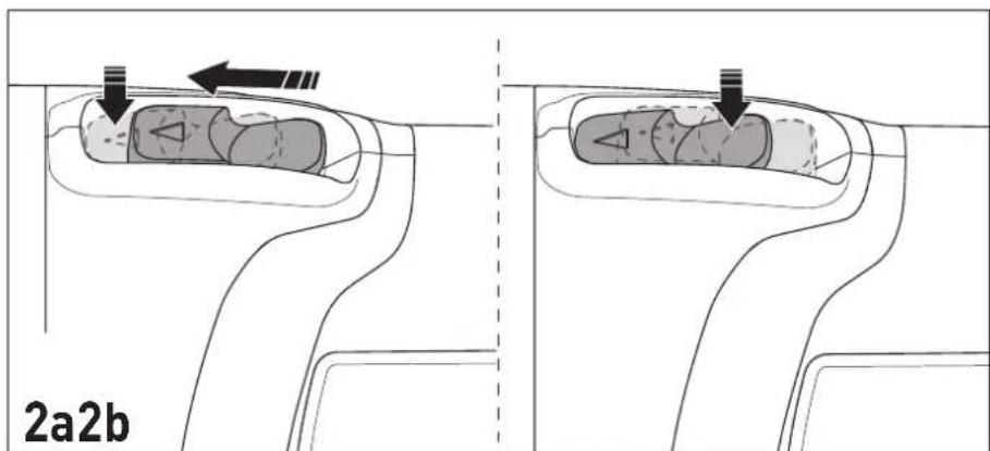
6.2 Switch on/off
Switching on [2a]
▶ Push the on/off switch [1-5] forwards.
Pressing the front part of the switch at the same time locks the on/off switch.
On/off switch [1-5] is locked and the power tool is switched on.
① Only position the tool on the material once it has reached operating speed.
Setting the speed
The speed can be adapted in six settings depending on the workpiece requirements.
▶ Set the speed regulator [1-4] to the required setting.
Switching off [2b]
▶ Lift the power tool from the processed material.
▶ Press the rear part of the on/off switch [1-5].
Lock is released and the power tool is switched off.
![FESTOOL AGC 18 - Switching off [2b] - 1](/content/2026/04/601805/images/9f0a43a2944e62249fa5b6b8da7f55bac2ca70bf534506018826afa72c811410.jpg)
WARNING
Risk of injury from kickback, ejected parts
▶ Before setting down the power tool, wait until the rotating sanding tool has come to a complete stop.
▶ Set the power tool down on the support points [1-11].
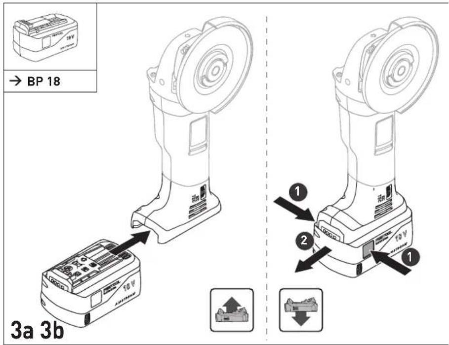
7 Battery pack
▶ Inserting the battery pack [3a]
▶ Removing the battery pack [3b]
7.1 Capacity display
The capacity display [1-10] indicates the charge of the battery pack for approx. 2 seconds after the button [1-9] is pressed:
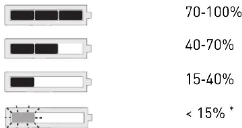
bar
| Range | Percentage (%) | |---|---| | 70-100% | 70-100 | | 40-70% | 40-70 | | 15-40% | 15-40 | | < 15% * | < 15% |* Recommendation: Charge the battery pack before any further use.
i Further information about the charger and battery pack with capacity indicator can be found in the corresponding operating manual.
8 Settings

WARNING
Risk of injury
- Remove the battery pack from the power tool before performing any work on the power tool.
8.1 Fitting the auxiliary handle [1-6]
![FESTOOL AGC 18 - Fitting the auxiliary handle [1-6] - 1](/content/2026/04/601805/images/ce95bb607602619de10567dea4ad797605ee7b76860e11ab9181eb551ba7887b.jpg)
Always use the auxiliary handle to ensure a safe working posture that prevents you from tiring.
The special "VIBRASTOP" design of the auxiliary handle helps to reduce vibrations.
- Screw in the auxiliary handle [1-6] on the side of the thread [1-3] according to the working method.
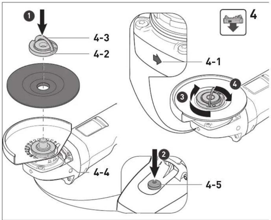
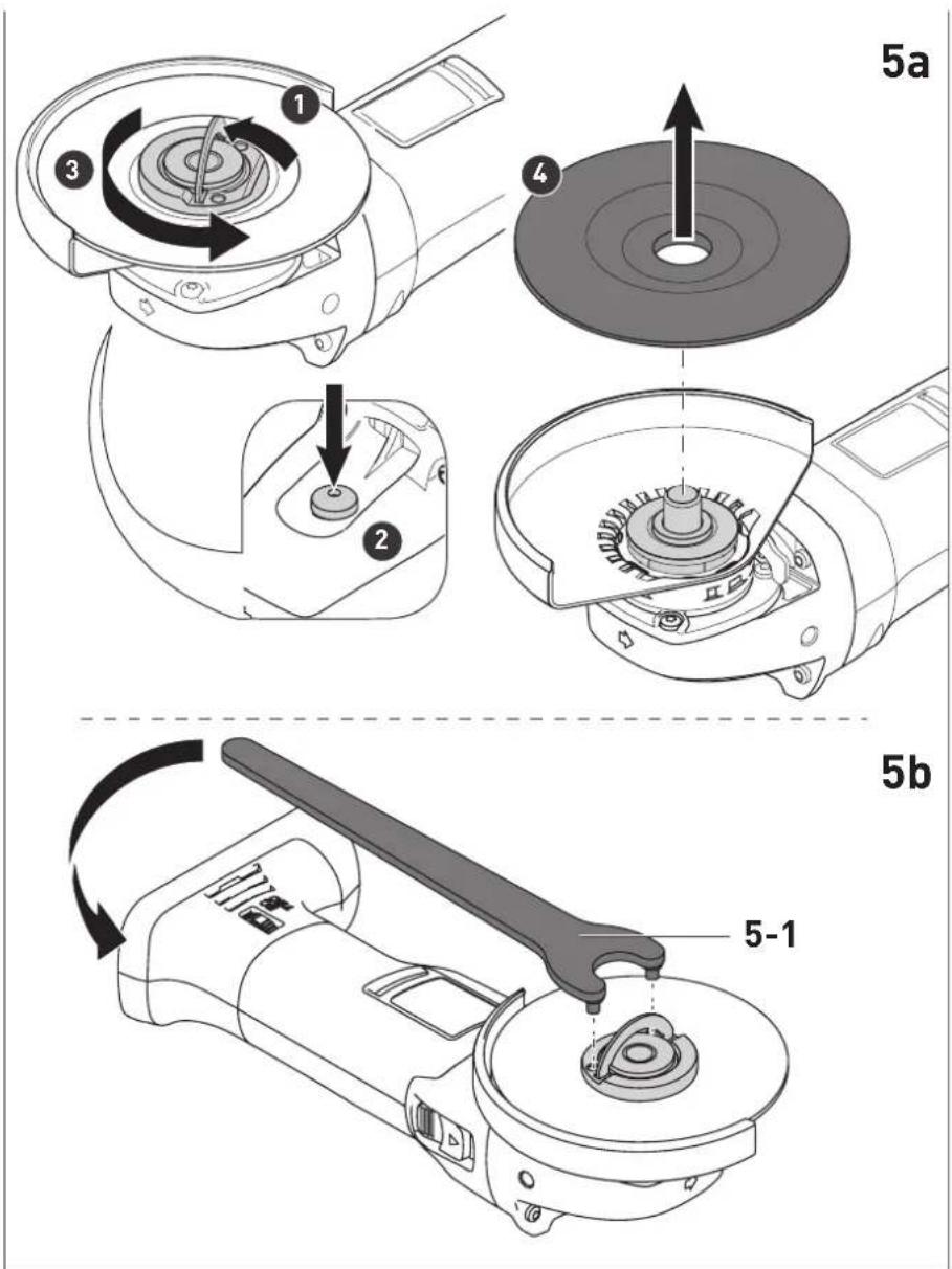
8.2 Fitting the sanding tool [4]
![FESTOOL AGC 18 - Fitting the sanding tool [4] - 1](/content/2026/04/601805/images/63d7674aa91507bc693ad805f90bb8761ae2f264bb67a5dc27c701be3d17a9c2.jpg)
![FESTOOL AGC 18 - Fitting the sanding tool [4] - 2](/content/2026/04/601805/images/cdfebab0a28a7cb93344889c73445d243962a42bf7709a2e29db2f30a97c94f8.jpg)
CAUTION
Risk of injury from hot and sharp tool
▶ Do not use any vibrating, blunt or defective sanding tools.
▶ Do not use sanding tools that have been exposed to extreme humidity, moisture or high temperatures prior to installation.
▶ Wear protective gloves.

WARNING
Risk of injury from incorrectly fitted sanding tool
▶ Only fold up the lift-up handle [4-3] for the quick-action clamping nut when you are replacing the sanding tool.
▶ Ensure that the flange [4-4] is fitted on the spindle before installing the sanding tool.
① Only tighten or loosen the clamping nut by hand. Never use tools to loosen or tighten the lift-up handle.
If the nut can no longer be loosened by hand, it should only be loosened with a face wrench [5-1].
If the lift-up handle is loose or damaged, the clamping nut must no longer be used under any circumstances.
i Use the guard provided for the application in each case.
- Remove the battery pack from the power tool.
▶ Open the lift-up handle [4-3] for the quick-action clamping nut.
▶ Unscrew the quick-action clamping nut [4-2] by hand.
Place the sanding tool on the spindle and flange [4-4].
Ensure that the centring ridge of the flange fits exactly into the opening in the disc and
that the form-fit connection between the power tool/spindle and flange matches.
Ensure that the diameter of the power tool spindle matches the hole in the sanding tool.
i Offset sanding tools must be fitted so that their sanding area does not protrude beyond the edge of the guard.
Adhere to the stipulated rotational direction of the sanding tool (arrow on the sanding tool = arrow on the tool housing [4-1]).
- Place the quick-action clamping nut on the sanding tool and spindle.
▶ Press the spindle lock [4-5] on the reverse of the tool.
▶ Tighten the quick-action clamping nut by hand.
▶ Close the lift-up handle for the quick-action clamping nut.
▶ Check that the sanding tool is securely attached and fitted to the power tool.
▶ Let new sanding tools run for around one minute with no load as a test.
Removal is performed in reverse sequence to assembly [5a].
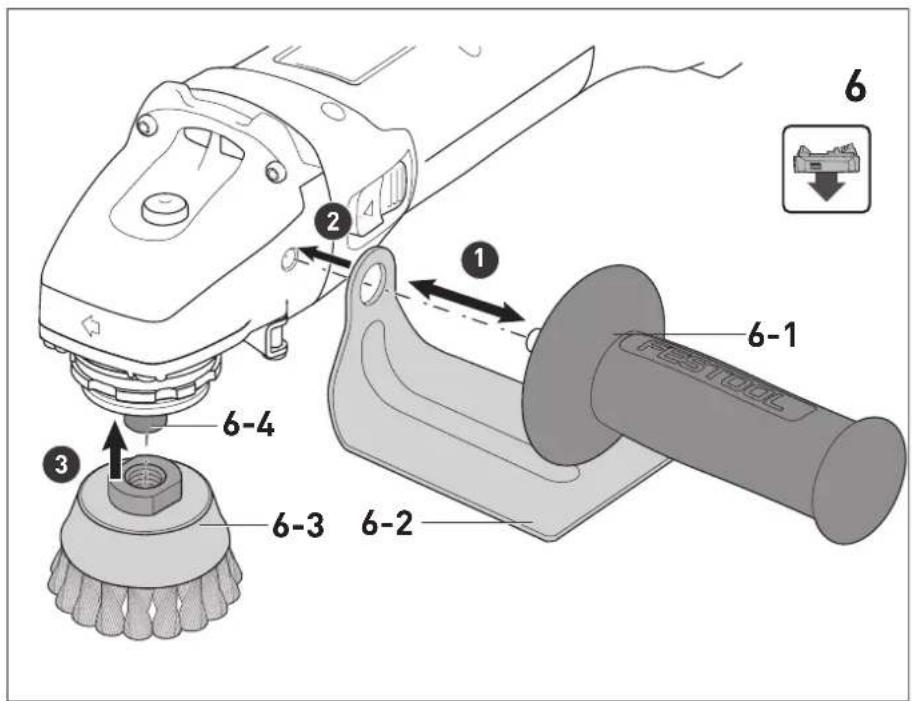
8.3 Fitting the wire brushes [6]
▶ Remove the handle [6-1].
▶ For the handle with hand protection [6-2].
▶ F the wire brushes [6-3] securely in the holding thread [6-4].
Observe the information provided for the wire brushes.
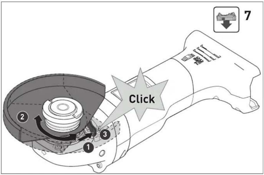
8.4 Positioning the guard/cutting guard [7]
The guard is preassembled. You can simply turn the guard to adapt its position to the requirements of the task.
▶ Press and hold the locking lever on the guard.
▶ A just the guard on the power tool so that sparks and particles are deflected away from the body.
▶ Release the locking lever and continue to turn the guard until it locks in place.
① The cutting guard, available as an accessory, can be positioned in the same way.
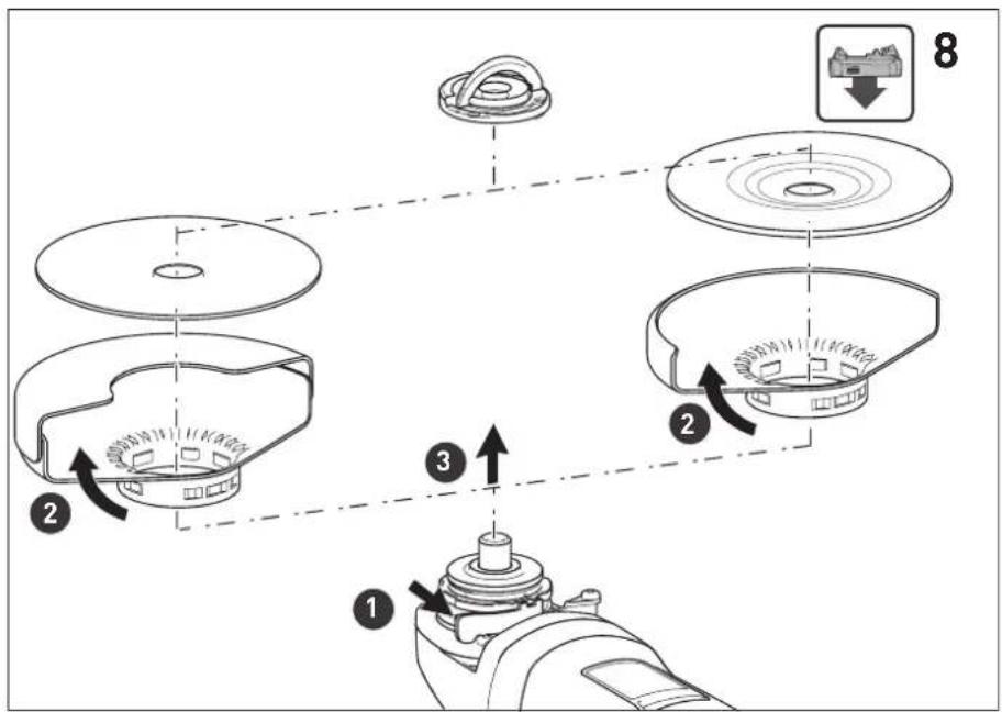
8.5 Removing the guard/cutting guard [8]
![FESTOOL AGC 18 - Removing the guard/cutting guard [8] - 1](/content/2026/04/601805/images/ca2e115ff59168323f38284066df4151979d2a2f4f715677b736487c61db91d7.jpg)
CAUTION
Risk of injury due to flying sparks and broken cutting discs.
- For abrasive cutting, use the cutting guard that is available as an accessory: See section 9.2
- Remove the sanding tool that has already been fitted to the power tool: See section 8.2.
▶ ① Press and hold the locking lever on the guard.
▶ After passing the pressure point, turn the guard forwards.
▶ Remove the guard from the power tool.
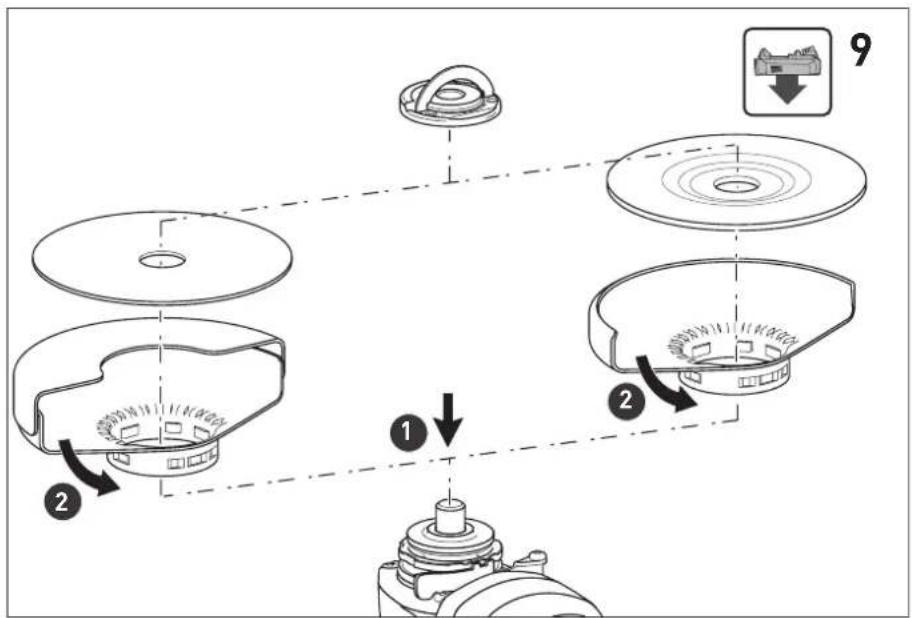
8.6 Fitting the guard/cutting guard [9]
NOTICE
Signs of wear on the cutting guard.
▶ Before switching on the sanding tool, check that it can move freely. The sanding tool must not sand against the cutting guard.
(i) Use the guard provided for the application in each case.
▶ Insert the guard in the front position. Make sure that the position of the pin and groove match.
▶ Turn the guard to the required position until the locking lever engages automatically.
To fit the sanding tool, see section 8.2.
9 Working with the electric power tool

WARNING
Risk of injury
▶ Only guide the power tool into the material when it is switched on (running).
▶ Always secure the workpiece in such a manner that it cannot move.
- Keep your hands away from the rotating sanding tools.

WARNING
Risk of injury from the fragile sanding tool
- Ensure that the sanding tool's expiry date has not been exceeded.

WARNING
Risk of injury due to moving workpiece
▶ Ensure that the workpiece is secure.

WARNING
Risk of injury from overhead work
▶ Always wear safety glasses for overhead work.
▶ Wear a P2 respiratory mask.
When not in use, the power tool can be set down on the support points [1-11].
- Remove the sanding tool from the power tool for transport.
9.1 Sanding
For sanding, always use the guard supplied with the tool.
The guard is preassembled. For how to remove the guard, see section 8.5.
9.2 Abrasive cutting
For abrasive cutting, always use the TSH-AGC 18-125 cutting guard that is available as an accessory.
The cutting guard is fitted, positioned and removed in the same way as the guard, see sections 8.5 and 8.6.
▶ Always guide the sanding tool through the workpiece in a straight line.
Ensure that the sanding tool does not tilt and that it is not loaded at an angle or from the side.
- For thick-walled workpieces, make a separating cut using oscillating movements while applying slight pressure to the power tool.
9.3 Working with wire brushes


WARNING
Risk of eye injuries caused by flying parts/wires
▶ Wear protective goggles.
For working with wire brushes, always use the HS-AGC18 hand protection that is available as an accessory, see section 8.3.
10 Acoustic warning signal
If the power tool switches off because of subsequent operating statuses, no warning signal sounds when it switches on.
Battery pack not accepted
English
- Insert the correct battery pack model.
Battery pack empty
- Change the battery pack.
- Charge the battery pack.
Battery pack fault
- Change the battery pack.
- Use the charger to check that the battery pack is fully functional once it has cooled down.
Battery pack overheated
- Let the battery pack cool down.
Power tool overheated
- The power tool must cool down before it can be started again.
Power tool fault
- Contact a Festool service workshop or specialist dealer.
Power tool jammed
- Eliminate the cause of the jam.
① If the power tool switches off when it becomes jammed, no warning signal sounds.
11 Accessories
Always use original Festool accessories, as described in the section on intended use. Using low-quality tools or accessories from other manufacturers may increase the risk of injury and seriously unbalance the machine, decreasing the quality of the working results and accelerating machine wear.
Refer to the Festool catalogue for the order numbers of accessories and tools or find them online at www.festool.co.uk.
12 Service and maintenance

WARNING
Risk of injury, electric shock
▶ Always remove the battery pack from the power tool before performing any maintenance or service work.
▶ All maintenance and repair work that requires the power tool to be opened up should always be carried out by an authorised service workshop.

Customer service and repairs must only be carried out by the manufacturer or service workshops. Find the nearest address at:
www.festool.co.uk/service
Always use original Festool spare parts. Order no. at: www.festool.co.uk/service
To ensure constant air circulation, always keep the cooling air openings in the motor housing clean and free of blockages.
When machining mineral materials (e.g. gypsum, etc.), dust deposits may build up in the power tool housing and on the on/off switch and harden when exposed to humidity. This may impair the switching mechanism and cause the power tool to overheat.
When machining metal, conductive dust deposits may build up inside the power tool. This can cause a short-circuit.
▶ After each machining process, blow out the inside of the power tool through the vents and the on/off switch using dry, oil-free compressed air.
Clean the sanding tools after use.
Keep the contacts on the power tool, charger and battery pack clean.
13 Environment

Do not dispose of the device in the household waste! Recycle devices, accessories and packaging. Observe applicable national regulations.
EU only: In accordance with the European Directive on waste electrical and electronic equipment and implementation in national law, used power tools must be collected separately and handed in for environmentally friendly recycling.
Information on REACH: www.festool.com/reach
14 General information
Imported into the UK by
Festool UK Ltd
1 Anglo Saxon Way
Bury St Edmunds
IP30 9XH
Great Britain
14.1 Bluetooth®
The Bluetooth ^® word mark and the logos are registered trademarks of Bluetooth SIG, Inc.; they are used by TTS Tooltechnic Systems AG & Co. KG, and therefore by Festool, under licence.
Sommaire
bar
| Range | Percentage (%) | |---|---| | 70-100% | 70-100 | | 40-70% | 40-70 | | 15-40% | 15-40 | | < 15% * | < 15% |bar
| Range | Percentage (%) | |---|---| | 70-100% | 70-100 | | 40-70% | 40-70 | | 15-40% | 15-40 | | < 15% * | < 15% |bar
| Range | Percentage (%) | |---|---| | 70-100% | 70-100 | | 40-70% | 40-70 | | 15-40% | 15-40 | | < 15% * | < 15% |Stille inn turtallet
natural_image
Four horizontal bars with black segments and a small rectangular object at the bottom, no text or symbols present.70-100%
40-70%
15-40%
< 15% *
natural_image
Four horizontal bars with black rectangular blocks and a small circular icon below, no text or symbols present.70—100%
40—70%
15—40%
< 15 % *


- Declaration of Conformity
- Ralf Brandt
- Head of Product Conformity
- Symbols
- Safety warnings
- General safety instructions
- Machine-specific safety notices
- Further safety instructions for all operations Kickback and Related Warnings:
- English
- Safety warnings specific for Grinding and Abrasive Cutting-Off Operations
- Additional safety warnings specific for Abrasive Cutting-Off Operations
- Safety Warnings Specific for Wire Brushing Operations
- Further safety warnings
- Safety warnings for sanding tools
- Emission levels
- CAUTION
- Noise generated when working
- Risk of damage to hearing
- Sanding
- Abrasive cutting
- The emission values may deviate from the specified values. This is dependent on how the tool is used and the type of workpiece being machined.
- Intended use
- Do not use this power tool for polishing, sanding surfaces using diamond discs or for applications involving diamond or hard ceramic discs.
- Technical data
- Parts of the machine
- Electronics
- Smooth start-up
- Speed regulator [1-4]
- Constant speed
- Recoil protection
- Restart protection
- Overheating protection
- Commissioning
- Holding the power tool correctly
- Switch on/off
- Switching on [2a]
- Setting the speed
- Switching off [2b]
- WARNING
- Risk of injury from kickback, ejected parts
- Battery pack
- Capacity display
- Settings
- Risk of injury
- Fitting the auxiliary handle [1-6]
- Fitting the sanding tool [4]
- Risk of injury from hot and sharp tool
- Risk of injury from incorrectly fitted sanding tool
- Fitting the wire brushes [6]
- Positioning the guard/cutting guard [7]
- Removing the guard/cutting guard [8]
- Risk of injury due to flying sparks and broken cutting discs.
- Fitting the guard/cutting guard [9]
- NOTICE
- Signs of wear on the cutting guard.
- Working with the electric power tool
- Risk of injury from the fragile sanding tool
- Risk of injury due to moving workpiece
- Risk of injury from overhead work
- Sanding
- Abrasive cutting
- Working with wire brushes
- Risk of eye injuries caused by flying parts/wires
- Acoustic warning signal
- Battery pack not accepted
- Battery pack empty
- Battery pack fault
- Battery pack overheated
- Power tool overheated
- Power tool fault
- Power tool jammed
- Accessories
- Service and maintenance
- Risk of injury, electric shock
- Environment
- General information
- Imported into the UK by
- Bluetooth®
- Sommaire
- Stille inn turtallet
Brand : FESTOOL
Model : AGC 18
Category : Grinder