PLANEX LHS 2 225 - Grinder FESTOOL - Free user manual and instructions
Find the device manual for free PLANEX LHS 2 225 FESTOOL in PDF.

| Product Type | Self-propelled wall and ceiling sander |
| Brand | Festool |
| Model | PLANEX LHS 2 225 |
| Power | 400 W |
| No-load speed | 5000 – 8500 rpm |
| Sanding stroke | 4 mm |
| Sanding pad diameter | 220 mm |
| Abrasive diameter | 225 mm |
| Length (without extension) | 1.2 m |
| Length (with one extension) | 1.65 m |
| Weight (short version) | 4 kg |
| Weight (long version) | 4.7 kg |
| Dust extraction connection | 36 mm (27 mm with adapter) |
| Power supply | Electric, plug-it mains cable |
| Self-propelled function | Yes, adjustable via suction regulator |
| Integrated lighting | Adjustable LED grazing light |
| Connectivity | Bluetooth® (model LHS 2 225 EQI) for Festool Work app |
| Variable speed | Yes, stepless adjustment wheel |
| Pad brake | Yes, virtually wear-free |
| Overload protection | Automatic shutdown in case of jamming or overheating |
| Maintenance | Regular cleaning of ventilation slots and sanding pad |
| Spare parts | Sanding pad, interface pad, StickFix abrasives, extensions |
| Repairability | Repairs only by authorized Festool service center |
| Safety | Safety switch, restart protection, double insulation |
| General information | Intended use for dry sanding on interior walls and ceilings |
Frequently Asked Questions - PLANEX LHS 2 225 FESTOOL
User questions about PLANEX LHS 2 225 FESTOOL
0 question about this device. Answer the ones you know or ask your own.
Ask a new question about this device
Download the instructions for your Grinder in PDF format for free! Find your manual PLANEX LHS 2 225 - FESTOOL and take your electronic device back in hand. On this page are published all the documents necessary for the use of your device. PLANEX LHS 2 225 by FESTOOL.
USER MANUAL PLANEX LHS 2 225 FESTOOL
natural_image
Exterior view of a black and silver cleaning tool with green handle (no text or symbols visible)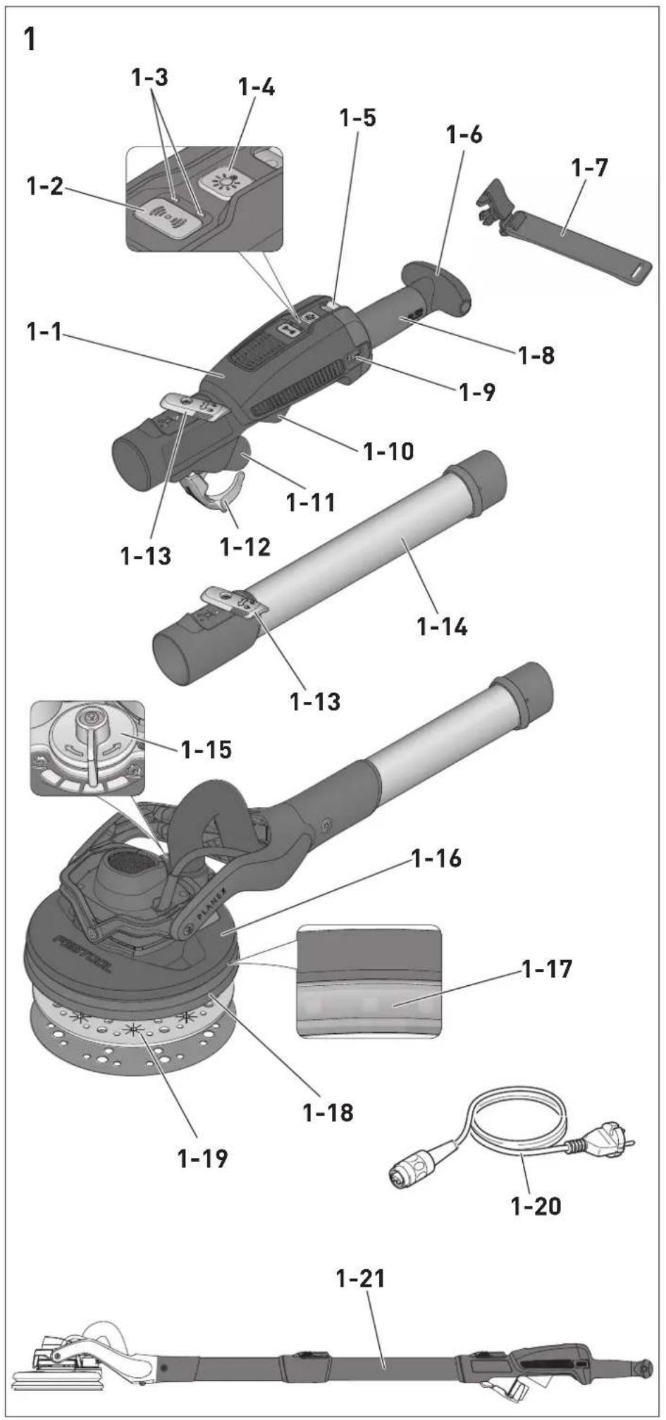
2


natural_image
Line drawing of a medical device with a checkmark overlay (no text or symbols)3


natural_image
Illustration showing a pen and a handheld device with a checkmark (no text or symbols present)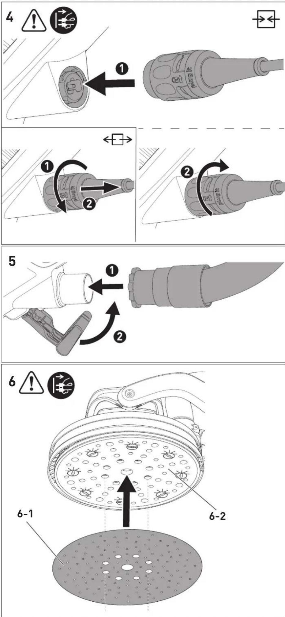
9
natural_image
Line drawing of a mechanical wrench tool (no text or symbols)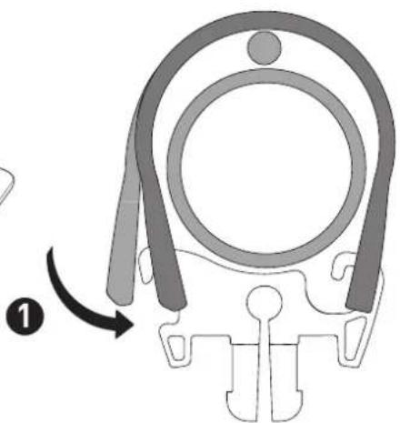
natural_image
Diagram of a mechanical component with curved arms and a central circular feature, no text or symbols present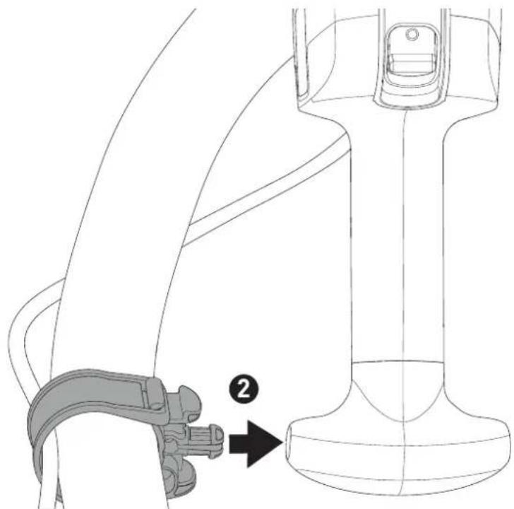
natural_image
Technical line drawing of a seatbelt buckle assembly with a numbered arrow indicating a step (no text or symbols present)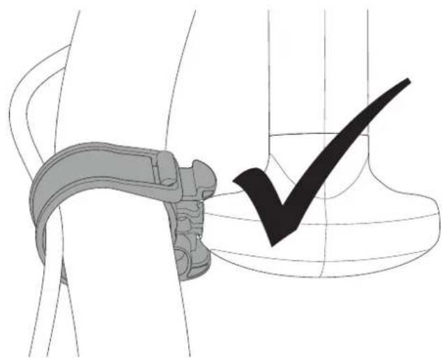
natural_image
Technical illustration of a mechanical clamp and a checkmark symbol (no text or labels)10
natural_image
Diagram showing a hand gripping a device against a shaded vertical wall, with no text or symbols present.Langhalsschleifer
Long-reach sander
Ponceuse à bras
Seriennummer 1)
Serial number 1)
N° de série 1)
(T-Nr.)
LHS 2 225 EQ 205212
LHS 2 225 EQI 10044087, 205214
de EU-Konformitätserklärung. Wir erklären in alleiniger Verantwortung, dass dieses Produkt mit allen relevanten Anforderungen folgender EU-Richtlinien übereinstimmt, und folgende Normen oder normative Dokumente zugrunde gelegt wurden:
en EU Declaration of Conformity. We declare under sole responsibility that this product complies with all the relevant requirements in the following EU Directives, and following standards and normative documents were applied:
fr Déclaration de conformité de l'UE. Nous déclarons, sous notre seule responsabilité, que ce produit satisfait à toutes les exigences pertinentes des directives UE suivantes et repose sur les normes ou documents normatifs suivants :
es Declaración UE de conformidad. Declaramos bajo nuestra responsabilidad que este producto cumple todos los requisitos relevantes de las siguientes directivas de la UE y que se han tomado como base las siguientes normas o documentos normativos:
it Dichiarazione di conformità UE. Dichiariamo sotto nostra unica responsabilità che il presente prodotto sia conforme a tutti i requisiti di rilevanza definiti dalle seguenti Direttive UE e che siano stati applicati le seguenti norme o i seguenti documenti normativi:
nl EU-conformiteitsverklaring. Wij verklaren en stellen ons ervoor verantwoordelijk dat dit product volledig voldoet aan alle volgende EU-richtlijnen en volgende normen of normatieve documenten daaraan ten grondslag gelegd werden:
SV EU-försäkran om överensstämmelse. Vi för- klarar på eget ansvar att denna produkt uppfyller alla relevanta krav enligt följande EU-direktiv och baseras på följande normer eller normgivande dokument:
fi EU-vaatimustenmukaisuusvakuutus. Vakuutamme yksinomaisella vastuulla, että tämä tuote täyttää seuraavien EU-direktiivien kaikki olennaiset vaatimukset ja se on seuraavien standardien tai standardiasia-kirjojen mukainen:
da EU-overensstemmelseserklæring. Vi erklærer med eneansvar, at dette produkt er i overensstemmel-se med alle relevante krav i følgende EU-direktiver, og at følgende standarder eller normative dokumenter danner grundlag for det:
nb EU-samsvarserklæring. Vi erklærer under eneansvar at dette produktet oppfyller alle relevante krav i følgende EU-direktiver og at følgende standarder eller normative dokumenter er blitt lagt til grunn:
Signed on behalf of and in name of/
Head of Product Development

Ralf Brandt
Head of Product Conformity
Declaration of Conformity
We as the manufacturer Festool GmbH, Wertstraße 20, 73240 Wendlingen, Germany declare under our sole responsibility that the product(s):
Designation:
Designation of Type(s):
Serial number(s) 1):
Long reach sander
LHS 2 225 EQI
205214, 10044087
fulfills all the relevant provisions of the following UK Regulations:
• S.I. 2008/1597 Supply of Machinery (Safety) Regulations 2008
• S.I. 2017/1206 Radio Equipment Regulations 2017
• S.I. 2012/3032 Restriction of the Use of Certain Hazardous Substances in Electrical and Electronic Equipment Regulations 2012
and are manufactured in accordance with the following designated standards:
• BS EN 62841-1: 2015
• BS EN 62841-2-4: 2014
• EN 300 328:2019 V2.2.2
• EN 301 489-1:2017 V2.1.1
• EN 301 489-17:2017 V3.1.1
• BS EN IEC 61000-3-2:2019
• BS EN 61000-3-3:2013
• BS EN IEC 63000:2018
11 in the specified serial number range (S-Nr.) from 400000000 - 499999999

Place and date of declaration: Wendlingen, 05.08.2021
Signed on behalf of and in name of Festool GmbH

Markus Stark
Head of Productdevelopment
i.v. Q Branch
Ralf Brandt
Head of Productconformity
Inhaltsverzeichnis
[1-19] Interface-Pad
$$ I = E I N, 0 = A U S $$
7 Einstellungen

WARNUNG
1 Symbols....24
2 Safety warnings....24
3 Intended use....26
4 Technical data.... 26
5 Parts of the device....26
6 Commissioning....27
7 Settings....28
8 Working with the electric power tool......30
9 Service and maintenance....31
10 Accessories.... 31
11 Environment....31
12 General information....32
13 Troubleshooting.... 32
1 Symbols

Warning of general danger

Warning of electric shock

Read the operating manual and safety warnings.

Wear ear protection.

Wear a dust mask.

Wear protective goggles.

Pull out the mains plug

Connecting the mains power cable

Disconnecting the mains power cable

CAUTION! Do not look directly into the light beam!

Do not dispose of it with domestic waste.

Safety class II

CE conformity marking

UKCA marking: Confirms the conformity of the product with UK regulations.

Tool contains a chip which stores data. See section 12.1

Tip or advice

Handling instruction
2 Safety warnings
2.1 General power tool safety warnings

WARNING! Read all safety warnings, instructions, illustrations and specifica-
tions provided with this power tool. Failure to follow all instructions listed below may result in electric shock, fire and/or serious injury.
Save all warnings and instructions for future reference.
2.2 Machine-specific safety notices
- This power tool is intended to function as a sander with abrasive. Read all safety warnings, instructions, illustrations and specifications provided with this power tool. Failure to follow all instructions listed below may result in electric shock, fire and/or serious injury.
- Do not use any insertion tools or accessories that the manufacturer has not specially designed or recommended for this power tool. Just because you can attach accessories to your power tool does not guarantee that they can be used safely.
- The outside diameter and the thickness of your accessory must be within the capacity rating of your power tool. Incorrectly sized accessories cannot be adequately guarded or controlled.
- Do not use a damaged accessory. Before each use inspect the accessory such as abrasives for chips and cracks, backing pad for cracks, tear or excess wear. If power tool or accessory is dropped, inspect for damage or install an undamaged accessory.
- Wear personal protective equipment. Depending on application, use face shield, safety goggles or safety glasses. As appropriate, wear dust mask, hearing protectors, gloves and workshop apron capable of stopping small abrasive or workpiece fragments. The eye protection must be capable of stopping flying debris generated by various operations. The dust mask or respirator must be capable of filtrating particles generated by your operation. Prolonged exposure to high intensity noise may cause hearing loss.
- Keep bystanders a safe distance away from work area. Anyone entering the
work area must wear personal protective equipment. Fragments of workpiece or of a broken accessory may fly away and cause injury beyond immediate area of operation.
- Hold the power tool by insulated gripping surfaces, because the sanding surface may contact its own cord. Cutting a "live" wire may make exposed metal parts of the power tool "live" and could give the operator an electric shock.
- Position the cord clear of the spinning accessory. If you lose control, the cord may be cut or snagged and your hand or arm may be pulled into the spinning accessory.
- Never lay the power tool down until the accessory has come to a complete stop. The spinning accessory may grab the surface and pull the power tool out of your control.
- Do not run the power tool while carrying it at your side. Accidental contact with the spinning accessory could snag your clothing, pulling the accessory into your body.
- Regularly clean the power tool's air vents. The motor's fan will draw the dust inside the housing and excessive accumulation of powdered metal may cause electrical hazards.
- Do not use accessories that require liquid coolants. Using water or other liquid coolants may result in electrocution or shock.
2.3 Further safety instructions
- Harmful/poisonous dust may be produced when working (e.g. paint products containing lead and some types of wood). Contact with or inhalation of this dust may pose a risk for the operating personnel or persons in the vicinity. Comply with the safety regulations that apply in your country. Connect the power tool to a suitable dust extractor.
- Wear suitable breathing protection to protect your health when large volumes of dust are generated and there is insufficient extraction. Ensure there is adequate ventilation in enclosed spaces.
-
Use a residual-current circuit breaker (RCCB) or an isolating transformer if operation of the power tool in a damp environment cannot be avoided. In the event of an electric shock, the residual-current circuit breaker (RCCB) or isolating transformer protects you against life-threatening current through the body.
-
If potentially explosive or self-igniting dust is produced during sanding, the machining instructions issued by the material manufacturer must always be followed.
- Caution: Fire hazard! Prevent the material being sanded and the sander from overheating. Always empty the dust container before taking breaks from work. Grinding dust in the filter bag and/or in the filter of the mobile dust extractor may ignite spontaneously under unfavourable conditions, such as flying sparks, when sanding. There is a particular risk if the sanding dust is mixed with clear coats or polyurethane residues or other chemical substances and the material being sanded becomes hot after it has been worked on for a long time.
- Metals and materials that contain asbestos must not be processed. Sparks may be created in the dust bag when processing metals. This increases the risk of fire.
- Hold the power tool firmly with both hands and maintain a stable stance when performing work. Using both hands ensures that the power tool is guided safely, see Section 8.1

- Warning of harmful light radiation. Do not look into the light beam for long periods. Do not direct the light beam towards other people or animals. Optical radiation can damage the eyes.
- Always use original Festool backing pads. Pads from other manufacturers can break.

- The light source fitted in this device must only be replaced by the manufacturer or a customer service workshop in order to ensure that your device operates reliably.
- Only for AS/NZS: The tool shall always be supplied via residual current device with a rated residual current of 30 mA or less.
2.4 Additional safety warnings for Australia
WARNING! The button battery or coin cell battery is hazardous and must be kept away from children, regardless of whether it is new or used.
- The button battery or coin cell battery can cause severe or fatal injuries in 2 hours or
English
less if it is swallowed or placed inside any part of the body.
- Medical attention should be sought immediately if it is suspected the button battery or coin cell battery has been swallowed or placed inside any part of the body.
2.5 Emission levels
The levels determined in accordance with EN 62841 are typically:
LHS 2 225 EQI/LHS 2 225 EQ
Sound pressure level L _PA = 70 dB(A)
Sound power level L _WA = 81 dB(A)
Uncertainty K = 3 dB

CAUTION
Noise emissions created while working with the power tool may damage your hearing.
▶ Always use ear protection.
Vibration emission level a_h (vector sum for three directions) and uncertainty K measured in accordance with EN 62841:
LHS 2 225 EQI/LHS 2 225 EQ a_h < 2.5 m/s^2
$$ K = 1. 5 \mathrm{m} / \mathrm{s} ^ {2} $$
The specified emission levels (vibration, noise)
- are used to compare machines.
- They are also used for making preliminary estimates regarding vibration and noise load during operation.
- They represent the primary applications of the power tool.

CAUTION
The emission values may deviate from the specified values. This is dependent on how the tool is used and the type of workpiece being machined.
▶ Assess the actual load during the entire operating cycle.
▶ Depending on the actual load, suitable protective measures must be defined in order to protect the operator.
3 Intended use
The long-reach sander is designed for sanding primed drywall constructions, ceilings and walls indoors as well as for removing carpet residue and coats of paint indoors.
A maximum of two extension tubes can be used.
The long-reach sander is not suitable for wet sanding and for working with oil and polishing agents.
Not suitable for continuous industrial operation.

The user is liable for improper or non-in-tended use.
4 Technical data
Long-reach sander LHS 2 225 EQI/
LHS 2 225 EQ
| Power 400 W | |
| Speed (no-load) 5000-8500 rpm | |
| Sanding stroke 4 mm | |
| Backing pad diameter 220 mm | |
| Abrasive diameter 225 mm | |
| Dust extraction connec-tion | 36 mm (27 mm) |
| Frequency 2402 Mhz - | 2480 Mhz |
| Equivalent Isotropically Radiated Power (EIRP) | <10 dBm |
| Short version length (without extension tube) | 1.2 m |
| Long version length (one extension tube) | 1.65 m |
| Weight as per EPTA-Procedure 01:2014 | |
| Long version (one ex-tension tube) | 4.7 kg |
| Short version (without extension tube) | 4 kg |
This tool has a light source of energy efficiency class E.
5 Parts of the device
[1-1] Handle
[1-2] Bluetooth® button (only LHS 2 225 EQI)
[1-3] LED indicator (only LHS 2 225 EQI)
[1-4] Surface control light button
[1-5] On/off switch
[1-6] T-handle
[1-7] Hose clip
[1-8] Handle
[1-9] Speed control
[1-10] Plug-it connection
[1-11] Extractor connector
[1-12] Suction sleeve stop
[1-13] Locking lever
[1-14] Extension tube
[1-15] Suction regulator
[1-16] Sanding head
[1-17] Surface control light
[1-18] Backing pad
[1-19] Interface pad
[1-20] Plug-it mains power cable
[1-21] Insulated gripping surfaces
The specified illustrations appear at the beginning of the Operating Instructions.
6 Commissioning

WARNING
Risk of injury, electric shock
▶ Always disconnect the mains plug from the socket before performing any work on the machine.
6.1 Assembling/disassembling

WARNING
Incorrect installation
Risk of injury from falling parts and loss of control
▶ Before switching on the power tool, make sure that all locking levers are completely closed.
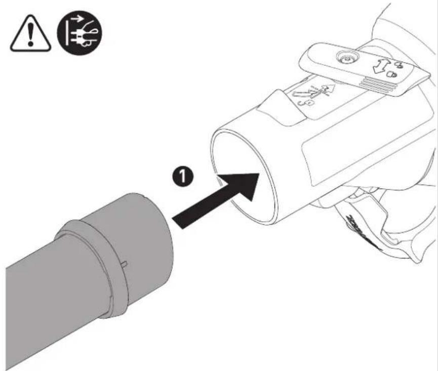
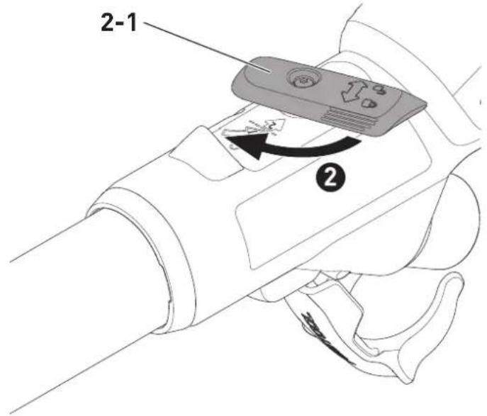
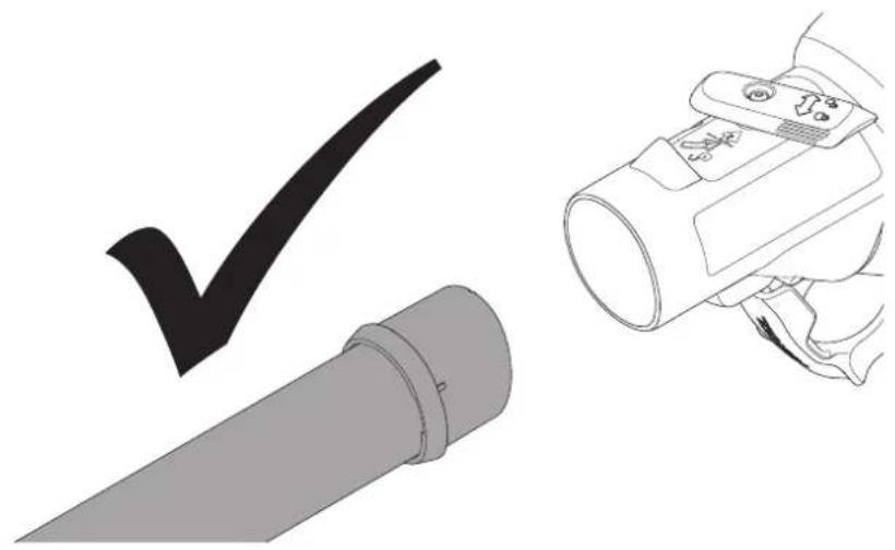
Assembly [2]
The long-reach sander consists of a LHS 2 225 EQI or LHS 2 225 EQ handle [1-1], a maximum of two extension tubes VL-LHS 2 225 [1-14] and a sanding head HE-LHS 2 225 [1-16].
- Push the pipe end of the sanding head into the opening on the handle as far as it will go.
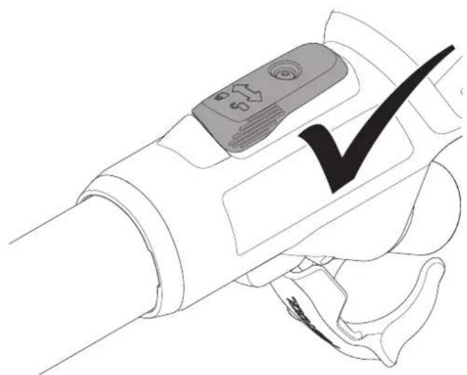
▶ Turn the locking lever [2-1] towards the sanding head as far as it will go.
▶ Check whether the handle and sanding head are firmly connected by pulling them apart.
☑ The handle and sanding head are securely connected.
Assemble the extension tubes in the same way as the handle.
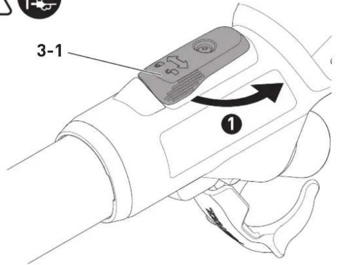
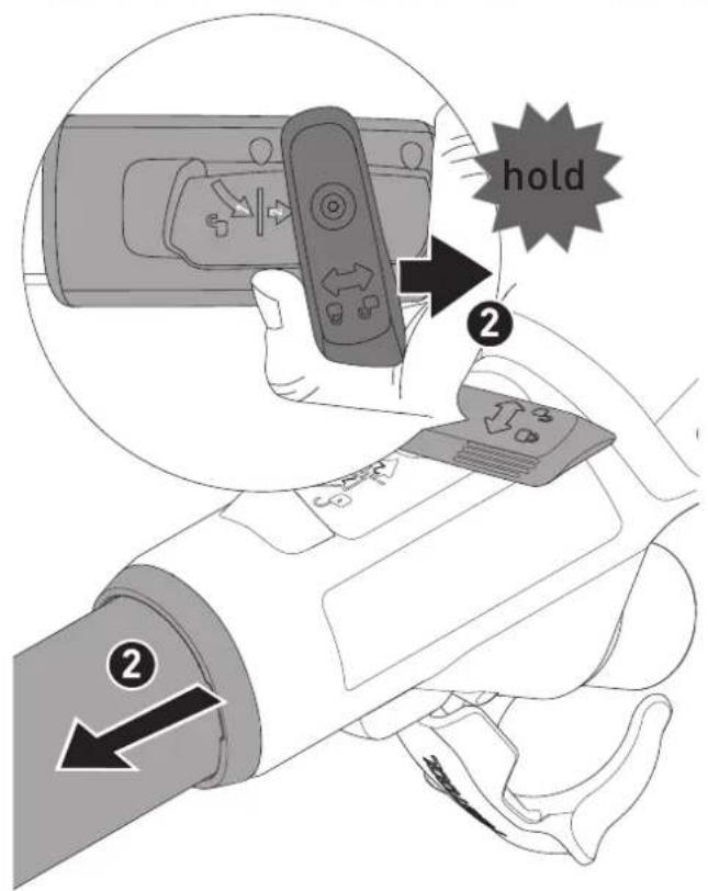
Disassembling [3]
▶ ① Open the locking lever [3-1].
▶ Turn the locking lever [3-1] further towards the end of the handle as far as it will go and hold it in this position. Pull the sanding head and handle apart at the same time.
☑ The sanding head and handle are separate and can be stored in a Systainer.
Disassemble the extension tubes in the same way as the handle.
6.2 Connecting

WARNING
Unauthorised voltage or frequency.
Risk of accidents
▶ The mains voltage and the frequency of the power source must correspond to the specifications on the name plate.
▶ In North America, only Festool machines with the voltage specifications 120 V / 60 Hz may be used.

CAUTION
Heating of the plug it connection if bayonet fitting is not completely locked
Risk of burns
▶ Before switching on the power tool, make sure that the bayonet fitting at the mains cable is closed fully and locked.
- Connect and disconnect the mains power cable [4].
▶ To connect the suction hose [5], see also Section 7.6.
Using a special vacuum sleeve, the PLANEX suction hose guarantees a permanent fixing and better protection against kinking.
6.3 Switching on/off
On/off switch [1-5]
$$ I = O N, 0 = O F F $$
7 Settings

WARNING
Risk of injury, electric shock
▶ Always disconnect the mains plug from the socket before performing any work on the machine.
7.1 Motor and electronics
The power tool is equipped with a brushless EC-TEC motor for a long service life and power electronics with the following properties:
Smooth start-up
The electronically controlled smooth start-up function ensures that the power tool starts up smoothly.
Speed control
You can use the adjusting wheel [1-9] to continuously adjust the speed within the speed range (see Section 4). This enables the sanding speed to be optimally adjusted to suit the material you are working on.
Constant speed
The preselected motor speed is kept constant through electronic control. This means that, if the machine is used as intended (reasonable contact pressure), a constant sanding speed is achieved.
Overheating protection
To avoid the power tool overheating, the power consumption is limited at an excessive temperature (e.g. if the pressure is too high while working). If the temperature continues to rise, the power tool switches off. It can only be switched on again once the power tool has cooled sufficiently.
Overload protection
The power tool will switch off if the backing pad becomes jammed or if the motor becomes overloaded, see also Section 13.
7.2 Changing the abrasives [6]
![FESTOOL PLANEX LHS 2 225 - Changing the abrasives [6] - 1](/content/2026/03/557540/images/be276d91f6b2d8e95affcb1443ae72c902e87c8b966fdab9d4455527f80d5623.jpg)
CAUTION
Deteriorated suction power and increased dust exposure
Heath hazard posed by dust
▶ The hole pattern in the abrasive must be aligned with the holes in the interface pad.
▶ Only use recommended abrasives with the appropriate hole pattern.
Compatible StickFix abrasives are quick and easy to attach to the interface pad.
▶ Press the abrasive [6-1] onto the interface pad [6-2].
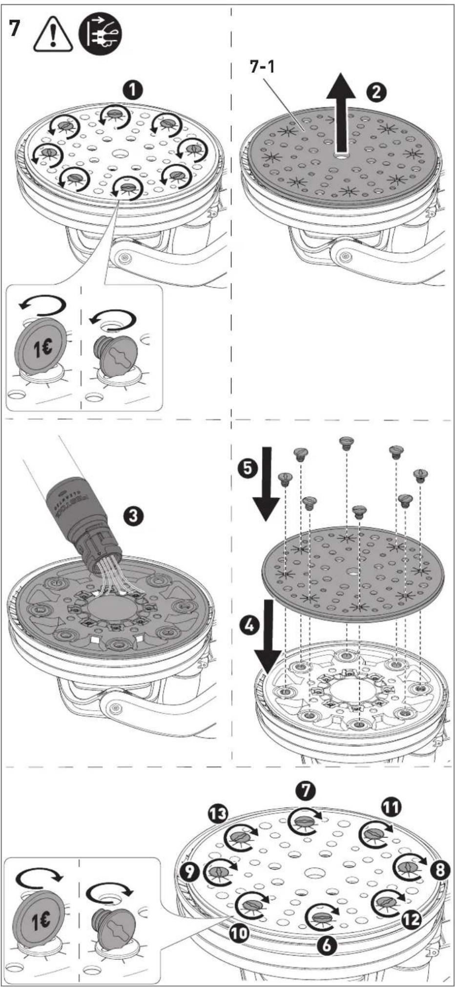
7.3 Changing the interface pad [7]
![FESTOOL PLANEX LHS 2 225 - Changing the interface pad [7] - 1](/content/2026/03/557540/images/ea7cf1644608d7f62ae1af2f3a3377036d68cddbc1a06a16f5c597a607fadde0.jpg)
CAUTION
Decreasing StickFix coating adhesion Risk of injury from flying parts
▶ Check the StickFix coating on the interface pad and the abrasive regularly for wear.
- Replace interface pad/abrasive with worn StickFix coating.

CAUTION
Risk of injury from fastening two interface pads on top of each other
Risk of injury from flying parts
▶ Always fasten just one interface pad to the power tool.
The interface pad is attached to the backing pad with eight screws.
▶ Remove the abrasive.
- Loosen the screws by turning the screwhead or a coin (e.g. a euro) anticlockwise.
▶ Remove the interface pad [7-1].
▶ Vacuum the backing pad and clean with a brush if necessary.
- Place a new interface pad on the backing pad.
▶ Insert all eight screws one after the other.
☑ The interface pad is optimally aligned.
▶ 6 Tighten all screws clockwise in a crosswise sequence.
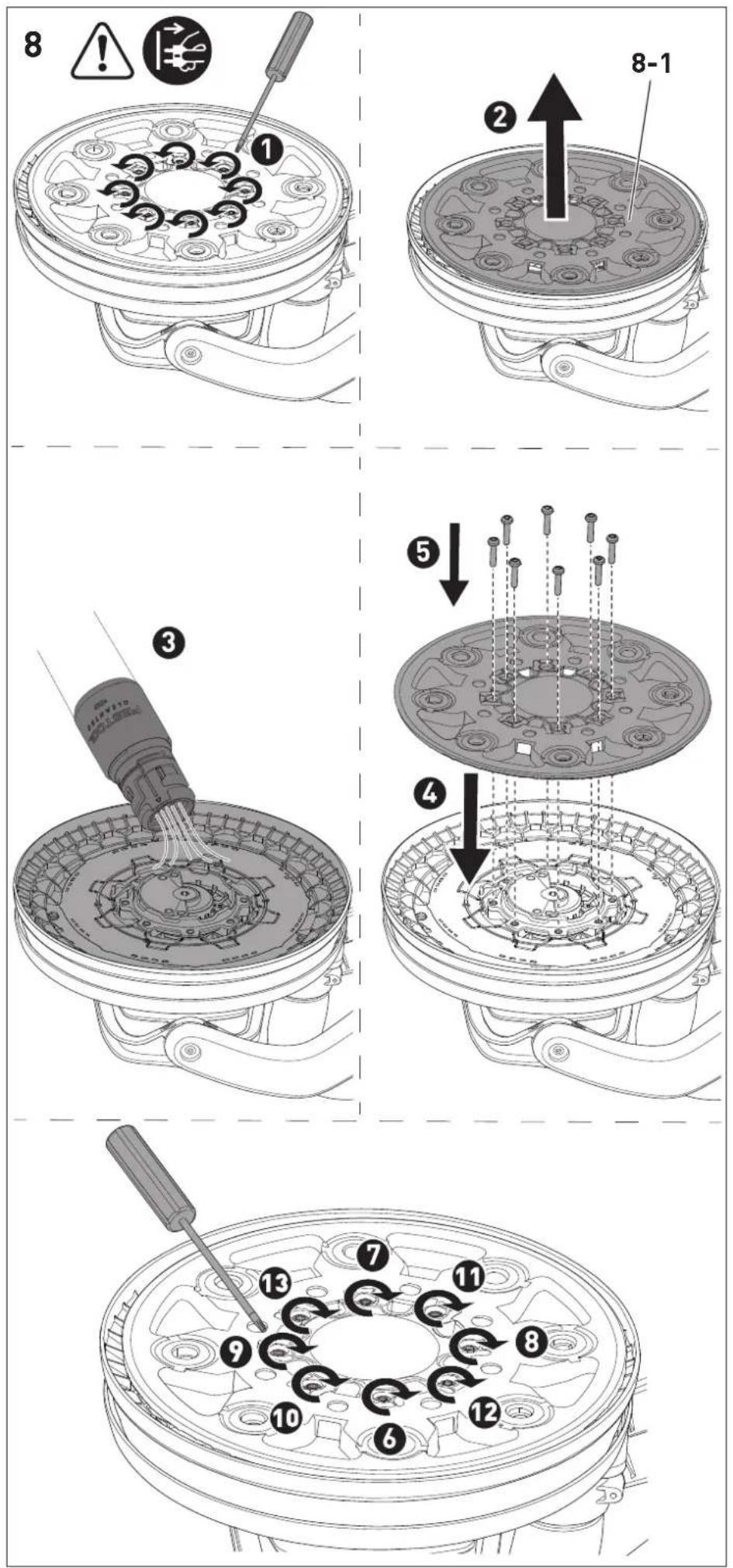
7.4 Replacing the backing pad [8]
![FESTOOL PLANEX LHS 2 225 - Replacing the backing pad [8] - 1](/content/2026/03/557540/images/56ff213f644a46ad70ade4a402e513915b219c27ae5b0f370d262320afd61555.jpg)
CAUTION
Worn backing pad, backing pad revs up Risk of injury from flying parts
▶ Check backing pad regularly for wear.
▶ Change backing pads if necessary.
The backing pad is attached to the power tool with eight screws.
▶ To remove the abrasive and interface pad, see Sections 7.2 and 7.3.
▶ Loosen the screws by turning a suitable screwdriver anticlockwise.
▶ Remove the backing pad [8-1] carefully by gently pulling it. Take care to ensure that no dirt enters the eccentric housing.
▶ Extract dirt particles if necessary.
- Place new backing pad so that the openings in the backing pad match with the screw threads.
▶ Insert all eight screws one after the other.
- 6 Tighten all screws clockwise in a crosswise sequence and check that they are securely in place.
7.5 Adjusting the suction power
The long-reach sander can adhere itself to the sanding surface, which helps you work more effortlessly.
▶ Set a low suction power.
▶ First, switch on the power tool and then place it on the sanding surface.
▶ Slowly increase the suction power until a noticeable application pressure is reached.

The suction regulator [1-15] can be used to adjust the suction power
according to the sanding surface.

Ceiling
Maximum suction power

Wall
Minimum suction power
If the suction power is set too high, this can lead to the power tool being overloaded, poor guidance or poor surface quality.
7.6 Dust extraction

WARNING
Health hazard posed by dust
▶ Always work with an extractor.
▶ Comply with national regulations.
▶ Wear a dust mask.
The power tool does not have its own extractor unit. A Festool mobile dust extractor with an extractor hose diameter of 36 mm or 27 mm should therefore be connected to the extractor connector [1-11] (36 mm recommended due to the reduced risk of clogging and higher suction power).
CAUTION! Always use an antistatic suction hose (AS). A slight electric shock may cause you to panic briefly and become distracted, which may result in an accident.
Always use the Festool CTL/M 36 E AC-LHS or PLANEX mobile dust extractor for the long-reach sander, as they are perfectly designed for large quantities of dust and have a dedusting system.
7.7 Adjusting the surface control light
The surface control light button [1-4] can be used to switch the surface control light on and off even when the power tool is switched off. The surface control light switches off after one hour when the power tool is switched off.
Controlling the surface control light via the Festool Work app\* (only LHS 2 225 EQI)
If the power tool is connected to the Festool Work app via Bluetooth® (see Section 7.8), the surface control light can be configured.
* Not available in all countries.
7.8 Connecting a power tool via Bluetooth® (only LHS 2 225 EQI)
Connecting to the Festool Work app\*
The power tool can be configured with the Festool Work app.
▶ Press the Bluetooth ^ button [1-2] on the power tool for approximately three seconds until the LED display starts to flash blue.
☑ For a period of 60 seconds, the power tool is ready for connection.
▶ Follow the instructions provided in the Festool Work app to authorise the secure connection.
By pressing the Bluetooth® button, you can switch between the factory settings of the power tool and the configurations in the Festool Work app.
* Not available in all countries.
Connecting to the mobile dust extractor
▶ Activate the mobile dust extractor's automatic mode (see the operating manual for the mobile dust extractor).
▶ Press the connection button on the mobile dust extractor or on the remote control once (see the operating manual for the mobile dust extractor/retrofit receiver module).
▶ Switch on the power tool.
☑ The mobile dust extractor starts up and the power tool is connected until the mobile dust extractor or the power tool is manually switched off. If another power tool is con-
nected via Bluetooth ^® to the mobile dust extractor, the connection is also lost.
LED indicator [1-3]
| LED indicator Meaning | |
| LED lights up green. | The configurations made in the Festool Work app are active, e.g. the surface control light has been dimmed. |
| LED flashes blue once. | After being switched on, the power tool searches for a mobile dust extractor ready for connection. |
| LEDs flash blue. | The power tool can be connected to a mobile device. |
| LED lights up blue. | The power tool can be connected via Bluetooth® to a mobile device or a mobile dust extractor. |
| LED flashes purple. | Software update mode active. |
| LED flashes red. | The power tool has overheated. Further information can be found in the Festool Work app and in Section 13. |
| LED lights up red. | There is an electronic fault. Further information can be found in the Festool Work app. If the fault persists, contact an authorised customer service workshop. |
8 Working with the electric power tool

WARNING
Risk of injury
▶ Always hold the power tool with both hands using the indicated gripping surfaces, see Section 8.1.
▶ Before switching on the power tool, make sure that all locking levers are completely closed.
8.1 Holding the power tool correctly
| Type of installation | Gripping surface |
| Handle + sanding head | Hold the handle [1-8] or T-handle [1-6] with one hand and the sanding head pipe [1-16] with the other hand. |
| Handle + extension tube + sanding head | Hold the handle [1-8] or T-handle [1-6] with one hand and the extension tube [1-14] with the other hand. |
| Handle + 2 extension tubes + sanding head | Hold the handle [1-8] or T-handle [1-6] with one hand and the first extension tube after the handle [1-1] with the other hand. |
8.2 Sanding
▶ To switch on the power tool, see Section 6.3.
- Place the sanding head parallel to the sanding surface.
▶ Perform the sanding work.
If the power tool beeps three times, there is a fault. For troubleshooting, see Section 13.
The restart protection prevents the machine from starting automatically after the power supply is interrupted (e.g. after a power failure). After a voltage interruption, switch the power tool on again.
Do not apply too much pressure on the power tool as this will cause it to overload. The best sanding result is achieved by the correctly set suction power without additional pressure on the power tool. The sanding performance and quality are mainly dependent on the selection of the correct abrasive.
8.3 Ceiling work

WARNING
If the suction is interrupted, there is a risk of injury from the power tool falling and loss of control
▶ Always hold the power tool with both hands using the indicated gripping surfaces, see Section 8.1.
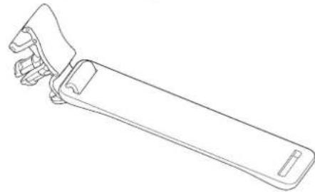
Attaching the hose clip [9]
When working on the ceiling, the hose clip prevents you from having to hold the hanging plug-it mains power cable and suction hose in your
hand, and also ensures that you have unrestricted freedom of movement.
▶ Pull out the mains plug.
▶ Attach the hose clip to the extractor hose and the plug-it mains power cable.
▶ Hook the hose clip to the right or left side of the T-handle.
If the hose clip is installed, it can be hooked into or unhooked from the T-handle depending on whether work is being carried out on the ceiling or on the wall.
8.4 After finishing work
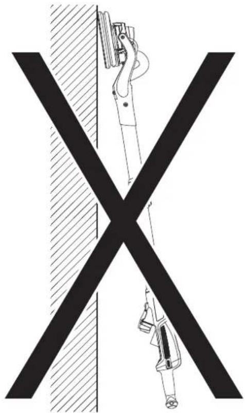
NOTICE
Damage and contamination of the power tool
▶ Do not set down the power tool on the backing pad [1-18] or T-handle [1-6] (see figure [10]).
▶ Always place the power tool on its side or use the PLANEX tool holder on the mobile dust extractor.
▶ Once you have finished the sanding work, switch off the power tool and set it down.
9 Service and maintenance

WARNING
Risk of injury, electric shock
▶ Always pull the mains plug from the socket before performing any servicing and maintenance work.
▶ All maintenance and repair work which requires the housing to be opened should always be carried out by an authorised service workshop.
Customer service and repairs must only be carried out by the manufacturer or service workshops. You must only use original Festool spare parts.
Further information: www.festool.co.uk/service
- Always state the serial number on the name plate of the handle [1-1] when having the tool serviced and repaired.
- Check the plug and cable on a regular basis and, if they are damaged, have them replaced by an authorised customer service workshop.
-
Do not clean the power tool with compressed air.
-
To ensure constant air circulation, always keep the cooling air openings in the motor housing clean and free of blockages.
- Vacuum the backing pad regularly.
- Keep all parts of the tool clean, especially the controls and housing openings, and clean them regularly with a brush.
9.1 Backing pad brake
The backing pad brake brushes off the backing pad and prevents uncontrolled turning of the backing pad. The backing pad brake is almost wear-free thanks to the pins used.
In the case of a decreasing braking effect, first check the backing pad for wear and replace it if necessary, see Section 7.4.
If the backing pad brake is damaged, it must be replaced by an authorised service workshop.
10 Accessories
Always use original Festool tools and original Festool accessories. Using low-quality tools or accessories from other manufacturers may increase the risk of injury and seriously unbalance the machine, decreasing the quality of the working results and accelerating power tool wear.
You can find the PO numbers for accessories and tools under www.festool.co.uk.
11 Environment
There is a Li-ion button cell behind the Bluetooth® button [1-2] (only LHS 2 225 EQI) on the handle [1-1].
Before disposal
Qualified specialist only: Remove the Li-ion button cell from the tool. To do so, unscrew the housing components and remove the Li-ion button cell.

Do not dispose of the device in the household waste! Recycle devices, accessories and packaging. Observe appli-national regulations.
Before disposal, users must remove lights that can be removed from the old device without causing damage.
In accordance with EU directives on waste electrical and electronic equipment and batteries and accumulators and their implementation in national law, faulty or used electrical equipment, batteries and battery packs must be collected separately and recycled in an environmentally friendly manner.
English
Information on collection points for proper disposal can be found at www.festool.co.uk/recycling.
Information on REACH: www.festool.co.uk/reach
Used or defective batteries must only be returned to collection points if discharged, secured against short-circuiting (e.g. by insulating the terminals with adhesive tape) and removed from the old device. The applicable regulations must be observed.
Batteries will then be recycled.
12 General information
12.1 Information on data privacy
The power tool contains a chip which automatically stores machine and operating data. The data saved cannot be traced back directly to an individual.
The data can be read in a contactless manner using special devices and shall only be used by Festool for fault diagnosis, repair and warranty processing and for quality improvement or en-
hancement of the power tool. The data shall not be used in any other way without the express consent of the customer.
12.2 Information about Bluetooth® (only LHS 2 225 EQI)
As soon as the tool is connected to the Festool Work app via Bluetooth® and the secure connection has been authorised, the tool will connect automatically to the Festool Work app from this point onwards. The tool then regularly sends status information (ID, operating status, etc.) via Bluetooth®.
The Bluetooth ^® word mark and the logos are registered trademarks of Bluetooth SIG, Inc.; they are used by TTS Tooltechnic Systems AG & Co. KG, and therefore by Festool, under licence.
Imported into the UK by
Festool UK Ltd
1 Anglo Saxon Way
Bury St Edmunds
IP30 9XH
Great Britain
13 Troubleshooting
The LED signals described in the table and errors relating to the Bluetooth® connection or the Festool Work app are only relevant for the LHS 2 225 EQI.
Problem Possible causes Remedy
| Power tool bumps/does not run smoothly over the surface. | Suction power is set incorrectly. | Adjust the suction power until the cause has been rectified, see Section 7.5. |
| Interface pad is damaged or deformed. | Replace the interface pad, see Section 7.3. | |
| Speed is set incorrectly. Increase the speed. | ||
| Power tool does not stop at ceiling. | Suction power is set incorrectly. | Increase the suction power, see Section 7.5. |
| Grit on abrasive is too coarse. Select a finer grit, e.g. P240, P320. | ||
| Extraction power is insufficient. | See measures in the section entitled "Extraction power ... is insufficient." | |
| Excessive material removed from workpiece. | Suction power of the power tool is too strong. | Reduce the suction power until the cause has been rectified, see Section 7.5. |
| Grit on abrasive is too coarse. Select a finer grit, e.g. P240, P320. | ||
| Speed of the power tool is too high. | Reduce the speed, see Section 7.1. | |
| Packling paste with a high percentage of filler/soft filler. | Reduce the speed, see Section 7.1. | |
Problem Possible causes Remedy
| Surface quality is not optimal. | Incorrect abrasive grit. Select a finer grit, e.g. P240, P320. | |
| Drying times of the spackling paste not observed. | Read the technical data sheets and manufacturer's recommendations. | |
| Suction power of the power tool is set incorrectly. | Adjust the suction power until the cause has been rectified, see Section 7.5. | |
| Spackling paste with a high percentage of filler/soft filler. | Select a finer grit, e.g. P240, P320. | |
| Scratch marks on the surface. | Backing pad is placed down on the surface at an angle. | Place the backing pad parallel to the surface. |
| Backing pad brake is worn. Have the backing pad brake replaced by an authorised customer service workshop. | ||
| Extraction power of the power tool is insufficient. | Holes in the interface pad or backing pad are clogged. | Vacuum the interface pad, backing pad and extraction channels. |
| Incorrect abrasive. Always use original Festool abrasives with the matching hole pattern. | ||
| Abrasive hole pattern does not match the interface pad hole pattern. | Apply abrasive correctly, see Section 7.2. | |
| Extraction power of the mobile dust extractor is insufficient. | Filter element on the CTL/M 36 E AC-LHS or PLANEX is blocked/clogged. | Clean the filter element regularly:- Use the mobile dust extractor's dedusting function (see the operating manual for the mobile dust extractor).- Manually clean the filter element (dust extraction).- Check the filter element for damage and clogging. Use a new filter element regularly. |
| Disposal bag inserted incorrectly. | The holes punched in the disposal bag must be inside the container. | |
| Filter bag used instead of disposal bag. | Only work with the disposal bag. | |
| The extraction power of the CTL/M 36 E AC-LHS or PLANEX is set too low. | Adjust the suction power to a higher setting. | |
| Suction hose is blocked or kinked. | Remove the blockage and straighten the hose. | |
| Disposal bag is full. Replace the disposal bag. | ||
| Speed drops significantly, power tool switches off, beeps three times and LED flashes red. | Power tool switches on overheating protection. | Switch off the power tool and allow it to cool down. Switch on again and allow it to continue cooling down in no-load mode. Then:- Reduce the suction power until the cause has been rectified.- Apply less pressure.- Switch it off and clean the housing openings. |
| After being switched on, the power tool is unstable when starting up, may switch off and may beep three times. | Power tool placed on the surface and only then switched on. | Switch on the power tool before placing it on the surface. |
Problem Possible causes Remedy
| The power tool does not function. The power tool may beep three times and the LED lights up red. | Restart protection activated. Interruption to the power supply, e.g. due to power failure or pulling out the mains plug. Switch the power tool off and on again. | |
| Plug-it mains power cable is not connected correctly. | Check whether the bayonet fitting on the plug-it mains power cable is completely closed and locked. | |
| Overload protection Apply less pressure on the power tool, remove the backing pad blockage or reduce the suction power. | ||
| Other causes Read the tool status with the Festool Work app (see Section 7.8) and follow the app's recommendations. | ||
| The LED flashes purple and the Bluetooth® functions of the power tool are not available. | Software update is interrupted or software update has failed. | Restart software update with the Festool Work app. |
| The surface control light does not switch on when the power tool is started and the LED may light up green. | Surface control light auto-start function is deactivated in the Festool Work app. | To switch to factory settings, see Section 7.8 or see the Festool Work app. |
| The surface control light is faulty. | Have the surface control light replaced by an authorised customer service workshop. | |
If problems other than those listed occur, please contact a Festool service workshop or local specialist dealer, see Section 9.
Sommaire
$$ I = \text { M A R C H E }, 0 = \text { A R R E T } $$
7 Réglages
AVERTISSEMENT
$$ I = O N, 0 = O F F $$
7 Impostazioni

AVVERTENZA
$$ I = A A N, 0 = U I T $$
7 Instellingen

WAARSCHUWING
[1-19] Interface-Pad
[1-20] plug it-nätkabel
[1-21] Isolerade handtagsytor
$$ I = T I L L, 0 = F R \text { ÅN } $$
7 Inställningar

WARNING
flowchart
graph LR
    A["LED Light"] <--> B["LED Light"]
$$ I = P \ddot {A} \ddot {A} L L E, 0 = P O I S P \ddot {A} \ddot {A} L T \ddot {A} $$
7 Asetukset

VAROITUS
$$ I = T A E N D, 0 = S L U K $$
7 Indstillinger

ADVARSEL
6.1 Montering/demontering

ADVARSEL
Feil montering
$$ I = P \mathring {A}, 0 = A V $$
7 Innstillinger

ADVARSEL
Skaderisiko, elektrisk støt
$$ I = O N, 0 = O F F $$
7 Ajustes

ADVERTÊNCIA
flowchart
graph TD
    A["Worker Icon"] --> B["LED"]
    B --> C["Arrow Left"]
    C --> D["LED"]
$$ I = Z A P, 0 = V Y P $$
7 Nastavení