
VIGI NVR1016H - Surveillance Camera TP-LINK - Free user manual and instructions
Find the device manual for free VIGI NVR1016H TP-LINK in PDF.

| Brand | TP-Link |
| Model | VIGI NVR1016H |
| Product type | Network Video Recorder (NVR) for surveillance cameras |
| Number of channels | 16 channels |
| Dimensions (approx.) | 260 x 235 x 45 mm |
| Weight (approx.) | 1 kg |
| Power supply | 12V DC power adapter included |
| Power consumption | ≤ 10 W (without hard drive) |
| Internal storage | 1 bay for 3.5-inch SATA hard drive (not included) |
| Video output | HDMI and VGA |
| Main features | Video recording, Plug and Play, remote management via VIGI app, Internet access via TP-Link ID |
| Network connectivity | 1 Ethernet LAN port 10/100 Mbps |
| Audio input | 1 audio input (AUDIO IN) |
| Audio output | 1 audio output (AUDIO OUT) |
| USB ports | 1 USB port for mouse (front panel) |
| Mouse included | Yes, USB mouse |
| Management software | VIGI Security Manager (Windows), VIGI app (iOS/Android) |
| Maintenance and cleaning | Unplug the device before cleaning; use a soft, dry cloth |
| Security | Administrator password, physical reset button, firmware update |
| Spare parts and repairability | Replaceable hard drive, external power supply. No official spare parts listed |
| General information | TP-Link limited warranty; CE certification; operating temperature: 0°C to 40°C |
Frequently Asked Questions - VIGI NVR1016H TP-LINK
User questions about VIGI NVR1016H TP-LINK
0 question about this device. Answer the ones you know or ask your own.
Ask a new question about this device
Download the instructions for your Surveillance Camera in PDF format for free! Find your manual VIGI NVR1016H - TP-LINK and take your electronic device back in hand. On this page are published all the documents necessary for the use of your device. VIGI NVR1016H by TP-LINK.
USER MANUAL VIGI NVR1016H TP-LINK
Note: images may differ from the actual products.
Hard Drive Installation
For first time installation, please prepare a 3.5-inch hard disk drive (HDD). It is recommended to use the HDD of enterprise or surveillance level. Before installation, please disconnect the power from the network video recorder (NVR).
1 Remove the fixing screws on the side and back panels to open the cover of the NVR.
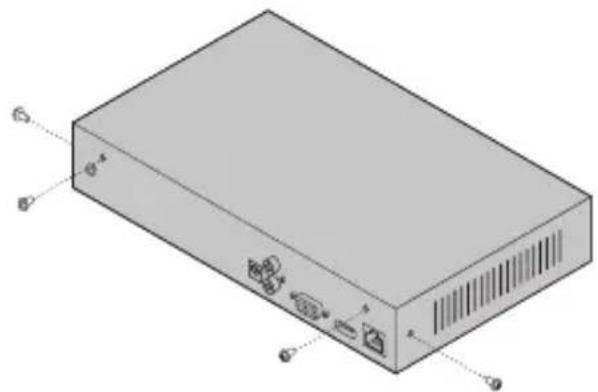
natural_image
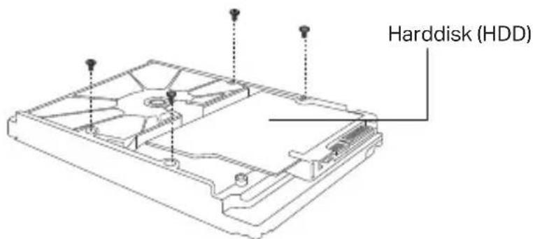
Isometric diagram of a rectangular electronic device with labeled ports and connectors (no text or symbols present)2 Attach the 4 included HDD screws to your hard drive. Do not fasten.
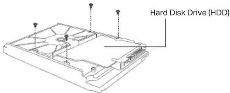
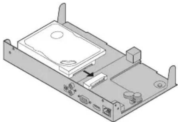
3 Match the 4 screws on the HDD with the 4 holes on the NVR, and insert the HDD interface into the slot.
natural_image
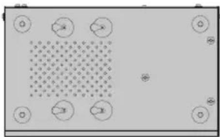
Isometric technical diagram of a computer chassis with labeled components (no text or symbols)4 Flip the NVR upside down and fasten the HDD screws. Replace the cover and fasten the screws of the NVR.
natural_image
Top-down view of a room with circular elements and a patterned area (no text or symbols)Hardware Connection
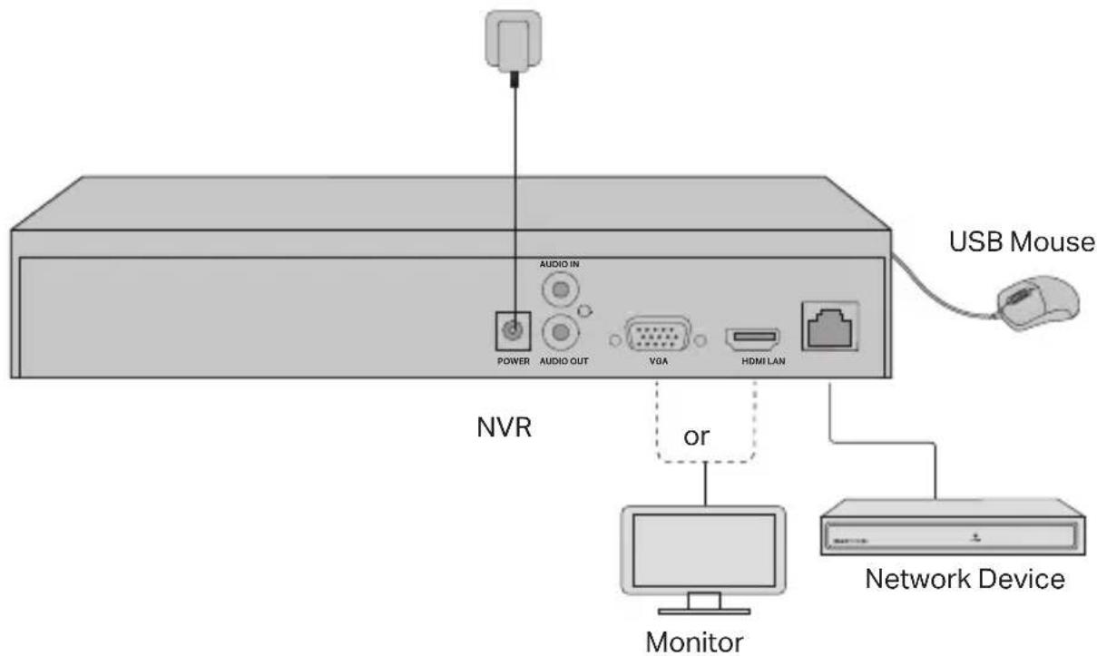
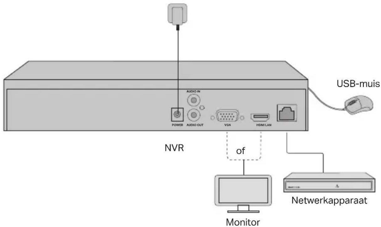
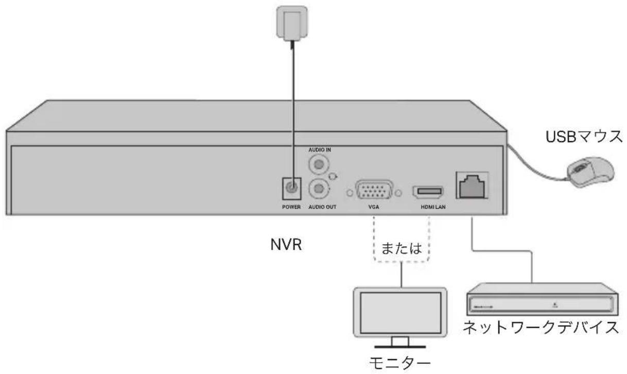
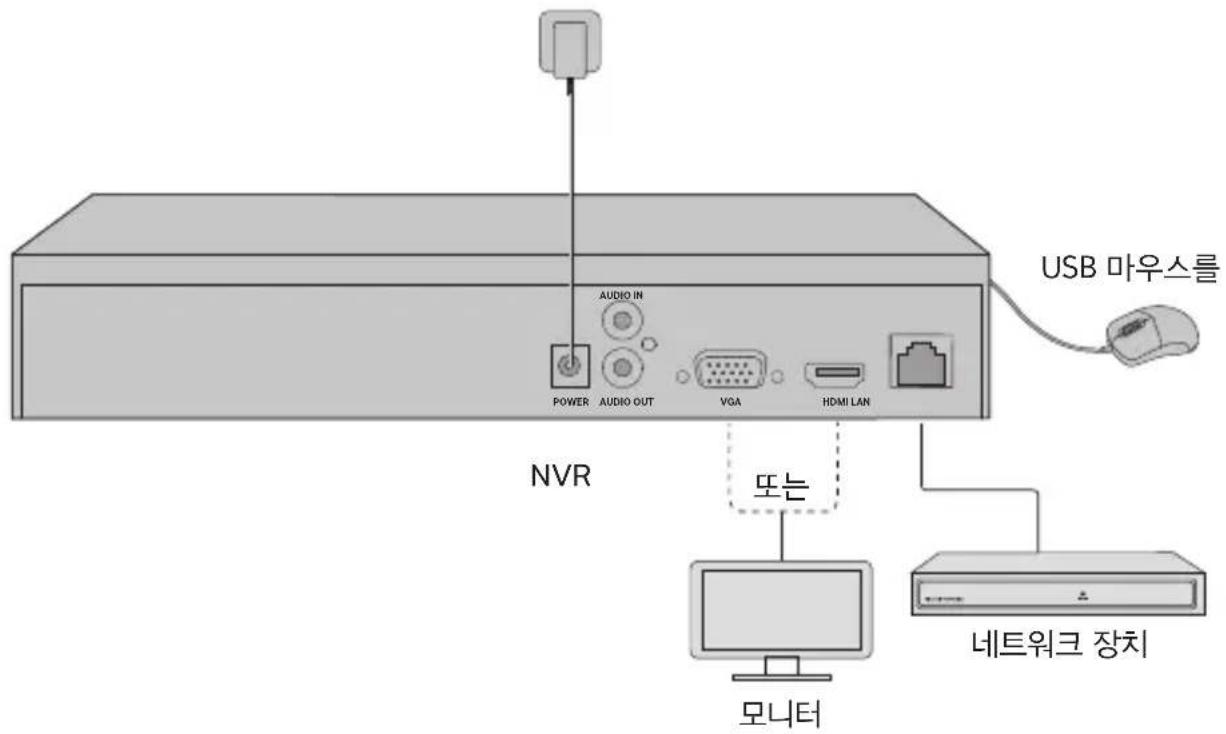
1 Connect your monitor to the HDMI or VGA port according to the connection port it supports
2 Connect your monitor to a power source and turn it on
3 Connect the LAN port of the NVR to a network device with an Ethernet cable.
4 Connect the provided USB Mouse to the USB Interface of the NVR (front panel).
5 Connect the power adapter to the NVR.
Cautions
- If you want to turn off the NVR after hard drive installation, click the Power button on the Main Menu of your monitor. Do not unplug it directly.
- The input voltage should match with the device power requirements.
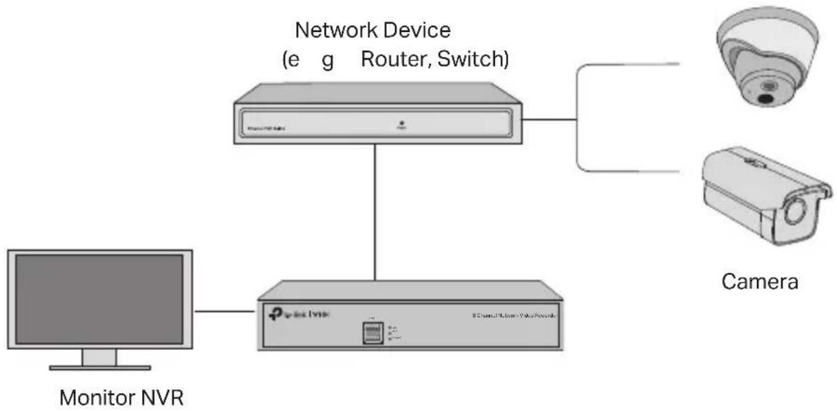
Network Topology
flowchart
graph TD
    A["Monitor NVR"] --> B["Network Device (e g Router, Switch)"]
    B --> C["Camera"]
    B --> D["8 Channel Network Voice Network"]
Step 1. Connect your cameras to the same network as your NVR.
Step 2. Follow the instructions to finish Quick Setup.
1 Create a login password for the NVR and a preset password for your unset cameras
2 Enable Plug and Play and the NVR will automatically find and add your cameras in your network
3 Follow Quick Setup to complete the settings of the NVR.
Note: For more instructions, please refer to the NVR's User Guide.
Step3 (Optional). Bind your NVR to a TP-Link ID for remote access and management. (Internet required)
Note: If you don't have a TP-Link ID, sign up first.
More Management Methods
■ VIGI Security Manager (Windows only)
You can use the VIGI Security Manager to view live video and modify NVR settings on your computer. Please Download it on your computer at https://www.tp-link.com/download-center/
VIGI App
The VIGI App provides a simple and intuitive way to remotely view live video, manage NVR, and get instant alerts.

or


Scan the QR code to download and install the VIGI app from the App Store or Google Play
FAQ (Frequently Asked Questions)
Q1. What should I do if I forget the login password of my NVR?
A1 Click Forgot Password on the login page and then follow the instructions to reset the password
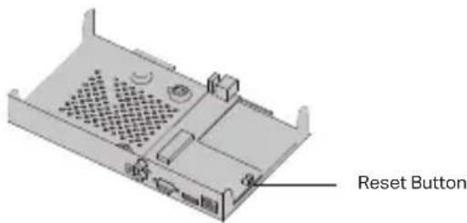
A2. Remove the cover, then press and hold the Reset button inside the NVR for over 3 seconds. The NVR will restore to the factory settings. Then follow Quick Setup to create a login password
Q2. What can I do if my NVR fails to connect to the Internet?
A1. Check if the internet is working properly.
A2. Make sure your NVR is in the same network segment as your network devices. For more details, please refer to the NVR's User Guide.
If you have more questions, please visit https://www.tp-link.com/support/faq/2850/
natural_image
Isometric diagram of a rectangular electronic device with ports and ventilation slots (no text or symbols)natural_image
Isometric technical diagram of a computer chassis with ports and connectors (no text or labels)natural_image
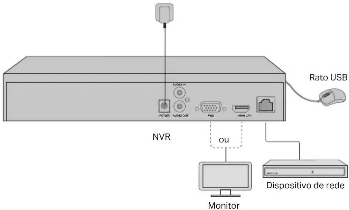
Top-down view of a rectangular electronic device with circular components and a central grid pattern (no text or symbols)Hardware-Verbindung

natural_image
3D diagram of a computer drive chassis with ventilation slots and ports (no text or symbols)Reset-Taste
natural_image
Isometric diagram of a rectangular electronic device with labeled ports (no text or symbols present)natural_image
Isometric technical diagram of a computer chassis with labeled ports and an arrow indicating a component (no text or symbols present)natural_image
Top-down view of a room with circular elements and a patterned area (no text or symbols)natural_image
Isometric illustration of a rectangular electronic device with labeled ports (no text or symbols beyond labels)natural_image
Isometric technical diagram of a computer chassis showing internal components and ports (no text or labels)natural_image
Abstract diagram with geometric shapes and dots, no readable text or symbolsΣύνδεση υλικού

natural_image
Isometric illustration of a rectangular electronic device with ports and ventilation slots (no text or symbols)natural_image
3D diagram of a computer chassis showing internal components and ports (no text or labels)Français
natural_image
Top-down view of a room with circular elements and a patterned area (no text or symbols)natural_image
3D diagram of a computer chassis with ventilation slots and ports, labeled 'Bouton' (no other text or symbols)natural_image
3D diagram of a rectangular electronic device with labeled ports (no text or symbols present)natural_image
Isometric technical diagram of a computer chassis with labeled ports and an arrow indicating a component (no text or symbols present)natural_image
Top-down view of a rectangular electronic device with circular components and a central grid pattern (no text or symbols)natural_image
Isometric view of a rectangular electronic device with ports and ventilation slots (no text or symbols)natural_image
Isometric technical diagram of a computer chassis with ports and connectors (no text or labels)natural_image
Top-down view of a room with circular elements and a patterned area (no text or symbols)Conexão de hardware
natural_image
3D rendering of a computer chassis with ventilation slots and drive bays (no text or symbols)Botão de reset
natural_image
Isometric diagram of a rectangular electronic device with labeled ports (no text or symbols beyond labels)natural_image
Isometric technical diagram of a computer chassis with ports and connectors (no text or labels)natural_image
Top-down view of a room with circular elements and a patterned area (no text or symbols)natural_image
Isometric illustration of a rectangular electronic device with labeled ports (no text or symbols beyond component labels)natural_image
Isometric technical diagram of a computer drive chassis showing internal components and ports (no text or labels)natural_image
Top-down view of a room with circular elements and a patterned area (no text or symbols)Aansluitingen
natural_image
3D diagram of a rectangular electronic device with labeled ports (no text or symbols present)natural_image
Isometric technical diagram of a computer chassis with ports and an internal component (no text or labels)natural_image
Top-down view of a room with circular elements and a patterned area (no text or symbols)Anslut hårdvara
natural_image
Isometric illustration of a rectangular electronic device with labeled ports (no text or symbols beyond component labels)2 Fest de 4 medfølgende HDD-skruene til harddisken. Ikke stram til.
natural_image
Isometric technical diagram of a computer chassis with ports and an internal component (no text or labels)4 Vipp NVR-en opp ned og fest harddiskskruene. Sett på dekselet og fest skruene på NVR-en.

natural_image
Top-down view of a room with circular elements and a patterned area (no text or symbols)Maskinvaretilkobling

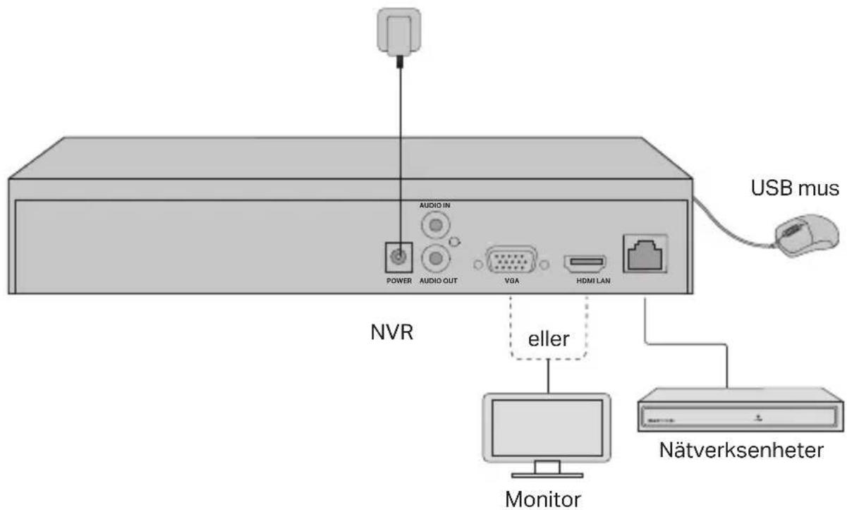
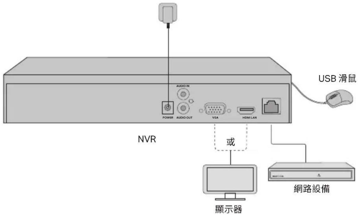
1 Koble skjermen til HDMI- eller VGA-porten i henhold til tilkoblingsporten den støtter.
2 Koble skjermen til en strømkilde og slå den på.
3 Koble NVR-ens LAN-port til en nettverksenhet med en Ethernet-kabel.
4 Koble den medfølgende USB-musen til NVR-ens USB-port (på frontpanelet).
5 Koble strømadapteren til NVR-en.
Forsiktighetsregler
natural_image
3D diagram of a computer drive chassis showing ports and connectors (no text or symbols)Tilbakestillingsknapp
Svar 1. Sjekk om internett fungerer ordentlig.
natural_image
Isometric illustration of a rectangular electronic device with ports and ventilation slots (no text or symbols)natural_image
Isometric technical diagram of a computer chassis with ports and a central component (no text or labels)natural_image
Abstract diagram with geometric shapes and dots, no readable text or symbolsnatural_image
Isometric diagram of a rectangular electronic device with labeled ports (no text or symbols present)natural_image
Isometric technical diagram of a computer chassis with ports and an internal component (no text or labels)natural_image
Top-down view of a room with circular elements and a patterned area (no text or symbols)atau


FAQ (Frequently Asked Questions)
natural_image
3D technical illustration of a computer drive chassis with ventilation slots and ports (no text or symbols)Tombol Reset
natural_image
Isometric diagram of a rectangular electronic device with ports and ventilation slots (no text or symbols)natural_image
Isometric technical diagram of a computer chassis showing internal components and ports (no text or labels)natural_image
Top-down view of a rectangular electronic device with circular components and a central grid pattern (no text or symbols)ハードウェアの接続
natural_image
3D technical illustration of a computer drive chassis showing ventilation slots and ports (no text or symbols)リセットボタン
natural_image
Isometric illustration of a rectangular electronic device with labeled ports (no text or symbols beyond component labels)natural_image
Isometric technical diagram of a computer chassis with labeled components (no text or symbols)natural_image
Top-down view of a rectangular panel with circular elements and a central patterned area (no text or symbols)하드웨어 연결
natural_image
Isometric view of a rectangular electronic device with ports and ventilation slots (no text or symbols)natural_image
Isometric technical diagram of a computer drive chassis showing internal components and ports (no text or labels)natural_image
Pure diagram of a rectangular area with circular elements and a central pattern, no text or symbols present.硬體連接
或


natural_image
3D technical illustration of a computer drive chassis with ports and connectors (no text or symbols)重設按鈕
natural_image
Isometric illustration of a rectangular electronic device with labeled ports (no text or symbols beyond labels)natural_image
Isometric technical diagram of a computer drive chassis showing internal components and ports (no text or labels)natural_image
Diagram showing a grid pattern with circular elements and directional arrows, no readable text or symbols present.natural_image
Isometric diagram of a rectangular electronic device with labeled ports (no text or symbols present)3 Match the 4 screws on the HDD with the 4 holes on the NVR, and insert the HDD interface into the slot.

natural_image
Isometric technical diagram of a computer drive chassis showing internal components and ports (no text or labels)natural_image
Top-down view of a rectangular electronic device with circular components and a central grid pattern (no text or symbols)Kết nối phần cứng
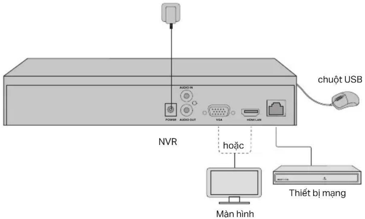
hoặc


natural_image
Isometric illustration of a rectangular electronic device with labeled ports (no text or symbols beyond labels)natural_image
Isometric technical diagram of a computer chassis showing internal components and ports (no text or labels)natural_image
Top-down view of a room with circular elements and a patterned area (no text or symbols)Donanım Bağlantısı

natural_image
3D technical illustration of a computer drive chassis with ventilation slots and connectors (no text or symbols)Reset Butonu
natural_image
Isometric illustration of a rectangular electronic device with labeled ports and connectors (no text or symbols)natural_image
Isometric technical diagram of a computer chassis showing internal components and ports (no text or labels)natural_image
Pure electrical circuit lines without any symbolsتوصل
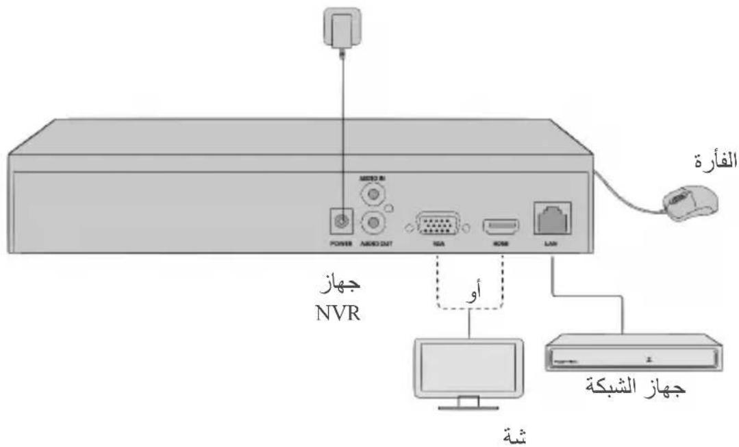
natural_image
3D technical illustration of a computer drive chassis with ports and connectors (no text or symbols)الظpzر
- Keep the device away from water, fire, humidity or hot environments.
- Do not attempt to disassemble, repair, or modify the device. If you need service, please contact us.
- Do not use damaged charger or USB cable to charge the device.
- Do not use any other chargers than those recommended.
- Adapter shall be installed near the equipment and shall be easily accessible.
- Use only power supplies which are provided by manufacturer and in the original packing of this product. If you have any questions, please don't hesitate to contact us.
- Avoid disposal of a battery into fire or a hot oven, or mechanically crushing or cutting of a battery, that can result in an explosion.
- Place the device with its bottom surface downward. Install it at stable places, and prevent it from falling.
CAUTION: RISK OF EXPLOSION IF BATTERY IS REPLACED BY AN INCORRECT TYPE. DISPOSE OF USED BATTERIES ACCORDING TO THE INSTRUCTIONS.
Please read and follow the above safety information when operating the device. We cannot guarantee that no accidents or damage will occur due to improper use of device. Please use this product with care and operate at your own risk.
TP-Link Limited Product Warranty
For TP-Link Branded Products Only. For more information about warranty, please visit http://www.tp-link.com/en/support.
THIS WARRANTY GIVES YOU SPECIFIC LEGAL RIGHTS, AND YOU MAY HAVE OTHER RIGHTS THAT VARY FROM STATE TO STATE (OR BY COUNTRY OR PROVINCE).
TO THE EXTENT ALLOWED BY LOCAL LAW, THIS WARRANTY AND THE REMEDIES SET FORTH ARE EXCLUSIVE AND IN LIEU OF ALL OTHER WARRANTIES, REMEDIES AND CONDITIONS.
TP-Link warrants the TP-Link branded hardware product contained in the original packaging against defects in materials and workmanship when used normally in according with TP-Link's guidelines for some period which depends on the local service from the date of original retail purchase by the end-user purchaser.
Español
TP-Link hereby declares that the device is in compliance with the essential requirements and other relevant provisions of directives 2014/30/EU, 2014/35/EU, 2009/125/EC, 2011/65/EU and (EU)2015/863.
The original EU declaration of conformity may be found at https://www.tp-link.com/en/support/ce/.
TP-Link hereby declares that the device is in compliance with the essential requirements and other relevant provisions of the Electromagnetic Compatibility Regulations 2016 and Electrical Equipment (Safety) Regulations 2016.
The original UK declaration of conformity may be found at https://www.tp-link.com/support/ukca/
Español
The terms HDMI, HDMI High-Definition Multimedia Interface, and the HDMI Logo are trademarks or registered trademarks of HDMI Licensing Administrator, Inc.

For technical support, the user guide and other information, please visit https://www.tp-link.com/support, or simply scan the QR code.


- Hard Drive Installation
- Cautions
- Network Topology
- Step 1. Connect your cameras to the same network as your NVR.
- Step 2. Follow the instructions to finish Quick Setup.
- Step3 (Optional). Bind your NVR to a TP-Link ID for remote access and management. (Internet required)
- More Management Methods
- ■ VIGI Security Manager (Windows only)
- VIGI App
- FAQ (Frequently Asked Questions)
- Σύνδεση υλικού
- Français
- Aansluitingen
- Forsiktighetsregler
- ハードウェアの接続
- TP-Link Limited Product Warranty
- Español
Brand : TP-LINK
Model : VIGI NVR1016H
Category : Surveillance Camera