
GD 320 - Drill FESTOOL - Free user manual and instructions
Find the device manual for free GD 320 FESTOOL in PDF.
| Product type | Drill guide stand |
| Brand | Festool |
| Model | GD 320 |
| Max drill bit length | 320 mm |
| Max drilling depth | 240 mm |
| Max drilling diameter without guide plate | 45 mm |
| Drilling diameter with guide plate | 8 to 26 mm |
| Weight | 2.8 kg |
| Height | 532 mm |
| Base dimensions | 185 x 172 mm |
| Adjustable parallel stop | 8 - 190 mm |
| Clamping collar diameter | 57/43 mm (with reduction) |
| Tilt | Not tiltable (drilling at 90°) |
| Recommended use | Precise perpendicular drilling |
| Safety | Use two hands, read instructions, unplug before maintenance |
| Maintenance | Clean guide rods, lightly lubricate |
| Spare parts | Use original Festool parts |
| Optional accessories | Guide plate for odd-sized drills, clamping devices, extensions |
| Repairability | Repair by manufacturer or authorized workshop |
| Compatible drill type | Power drills with 43 or 57 mm collar, max torque 75 Nm |
Frequently Asked Questions - GD 320 FESTOOL
User questions about GD 320 FESTOOL
0 question about this device. Answer the ones you know or ask your own.
Ask a new question about this device
Download the instructions for your Drill in PDF format for free! Find your manual GD 320 - FESTOOL and take your electronic device back in hand. On this page are published all the documents necessary for the use of your device. GD 320 by FESTOOL.
USER MANUAL GD 320 FESTOOL
natural_image
Two identical mechanical clamping devices with vertical rods and mounting bases, no visible text or symbols.GD 320
GD 460
GD 460 A
1 Technische Daten
| Maximum drill length 320 mm 460 mm 460 mm | |||
| Maximum drilling depth 240 mm 380 mm 310 mm | |||
| Guiding disk for drills | dia. 8, 10, 12 ... 26 mm | ||
| Maximum drilling dia. without guiding disk | 45 mm | ||
| Tilting at an angle | - | - | up to 45° steplessly |
| Clamping for drilling machines with clamping neck of the dia. | 57/43 mm | ||
| Weight | 2,8 kg | 3,2 kg | 3,7 kg |
| Overall height | 532 mm 672 mm | 672 mm | |
| Base board | 185 x 172 mm | 185 x 172 mm | 207 x 172 mm |
| Parallel stop - adjustable | 8 - 190 mm | ||
| - in vertical direction | - | - | 25-185 mm |
| Accessories, not included in the scope of the delivery | Order No |
| Guiding disk for spiral drills of the dia. 6,7,9,11 ... 27 mm | 621947 |
| Clamps (4 pcs) for clamping the stand for material up to 105 mm (up to 127 mm for GD 460 A) | 621949 |
| Brackets (2 pcs) for fastening the clamping elements stand up to the material width of 300 mm | 622471 |
2 Symbols

Warning of general danger

Read the operating instructions/notes!

Do not throw in the household waste!
i Advice or tip
3 Intended use
The drilling stands GD 320 and GD 460 are intended for precise drilling at the precise angle of 90°. By means of the guiding disk, it is possible to guide the spiral drills from dia. 8 to 26 mm, eventually, from dia. 6 to 27 mm, precisely and safely. Without a guiding disk, the maximum drilling depth is 45 mm. Two parallel stops server for a simple placement, or eventually, guiding on the material. The clamping elements for clamping the stand can be ordered as accessories. The stand can be employed with all electric drilling machines with the clamping neck of the dia. 57 or 43 mm that do not exceed the maximum torque of 75 Nm.
The drilling stand GD 460 A can be employed for drilling at an arbitrary angle in the range from 90° to 45°.
4 Safety Instructions
WARNING! Read all safety warnings and all instructions. Failure to follow the warnings and instructions may result in electric shock, fire and/or serious injury.
Save all warnings and instructions for future reference.
- The combination of the hand drilling machine with the stand creates a piece of equipment for which the safety and operating instructions for the drilling machine apply. Therefore, read also the safety and operating instructions for the drilling machine.
- During work, it is necessary to hold the equipment with both hands, gripping the respective handles.
- Before starting work, it is necessary to check and make sure that the rotating parts of the machine may not collide with the stable parts of the drilling stand or with the material during the drilling operation.
- Before starting work, it is necessary to check and make sure that all the elements intended for securing the position, the clamping etc., are well tightened and secured.
-
During the operation, the loose chips, splinters and similar pieces must not be removed from the vicinity of the tool by hand.
-
With drilling machines with a torque of more than 55 Nm, it is necessary to use always the extension piece for the additional handle.
- The material must always rest on a stable pad, and be secured against turning over and slipping.
- The tilting drilling stands (GD 460 A) must be always secured against shifting when drilling orifices at an angle. For this purpose, we recommend that you employ clamps (accessories).
- During work, stand always in a safe and stable position.
- During all the tasks that serve for the preparation, assembly, re-setting, adjustment, replacement of the drills or maintenance and care, it is always necessary to pull the plug of the drilling machine out of the mains.
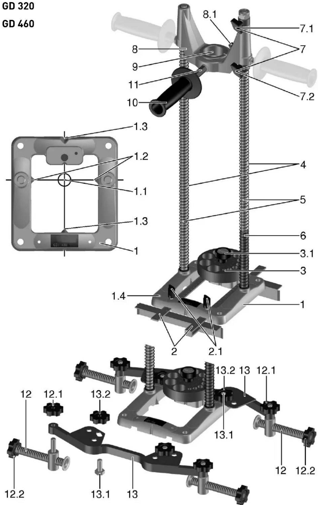
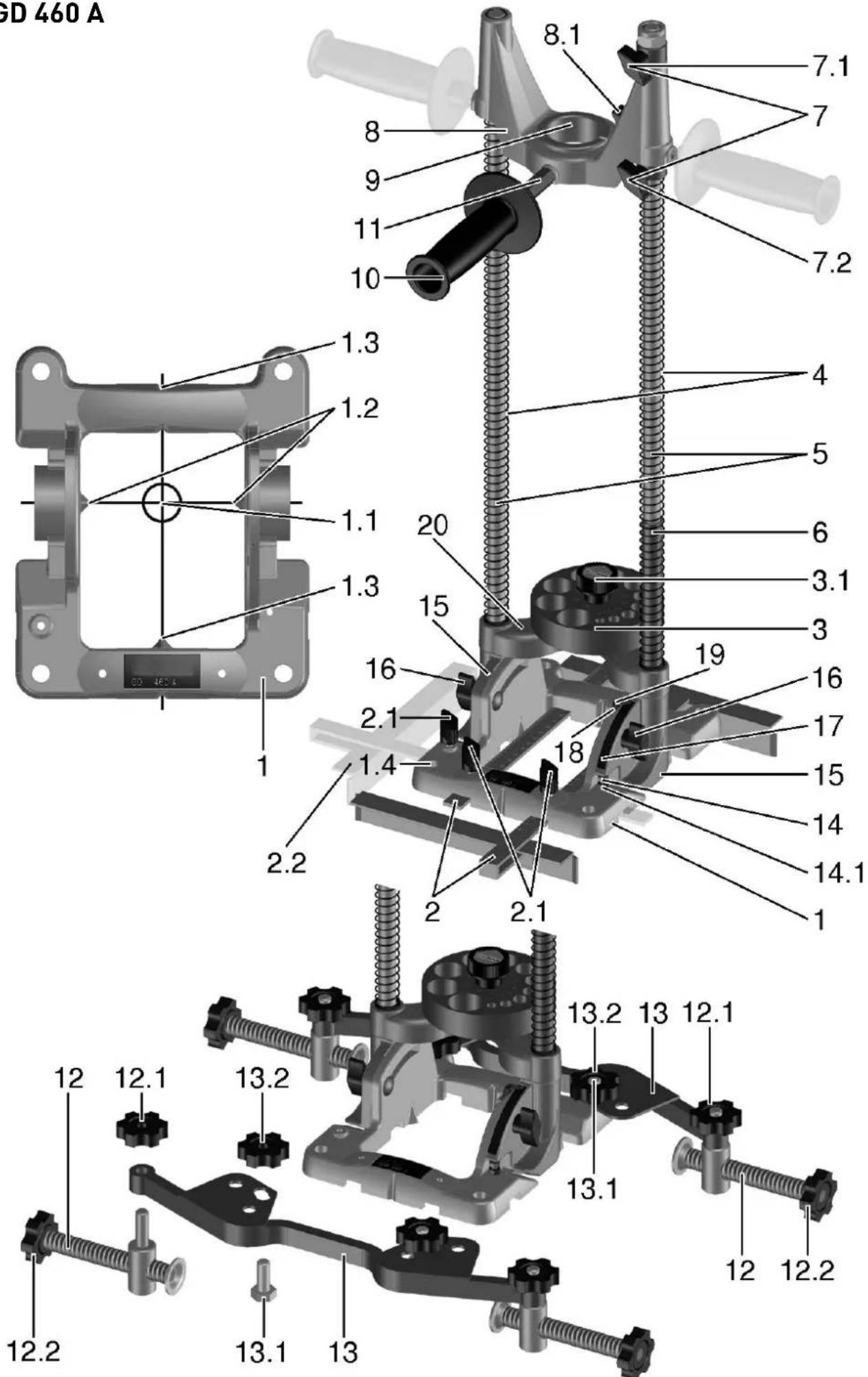
5 Machine features
1 Base board
2 Parallel guide
3 Guiding disk for drills
4 Guide bars
5 Springs
6 Stop tube
7 Depth stops
8 Guiding sleeve
9 Adapter D 57/43 mm
10 Additional handle
11 Extension piece for the additional handle
12 Clamps
13 Brackets
14 Screw for adjusting the vertical position
15 Feet
16 Clamping nut
17 Scale
18 Indicator
19 Clamping screw of the indicator
20 Yoke
All the accessories shown and described here are not included in the scope of the delivery.
The specified illustrations appear at the beginning of the Operating Instructions.
6 Bringing the Stand into Operation
6.1 Adjustment of the guiding disk
Choose the corresponding orifi ce in the guiding disk in compliance with the required drill diam-eter, and insert it into the axis of the drill (1.1):
▶ turn the rotary button (3.1) to the left through 5 revolutions approximately,
▶ lift the guide disk above the arresting pin,
▶ turn it to the required position and lower it back
upon the base board.
▶ Take care that the disk may engage with the locking pin.
▶ Retighten the rotary button (3.1).
6.2 Clamping of the drill
▶ Clamp the spiral drill into the chuck of the drilling machine, and tighten the chuck.
① It is allowed to employ only spiral drills of a length that does not exceed the indicated maximum drill length.
6.3 Clamping of the drilling machine

For the drilling machines with a clamping neck of the dia. of 43 mm, use a reducing ring.
▶ Situate the reducing ring in such a way that its notch may be directed to the clamping point [8.1] .
▶ Fit the drilling machine into the sleeve and tighten the clamping screw (8.1).
6.4 Adjustment of the drilling depth
▶ The upper limit of the stop is set up by means of the stop ring (7.1) and tightened with the clamping screw.
The position of the upper stop can be chosen in such a way that the drill may be directed by the guide ring, and the drill tip may be at a distance of 5 -10 mm from the surface of the base board.
In this way, you avoid a risk of damage to the drill or the material. The bottom stop ring (7.2) serves for limiting the drilling depth.
▶ Find out the required drilling depth by measuring or by a drilling test, and tighten the stop ring (7.2) under the sleeve.
The stop ring is of importance in particular if you are to drill several orifices of the same depth.
6.5 Additional handle
The additional handle (10) can be mounted in three positions according to choice (see the sketch). For the drills the torque of which exceeds 55 Nm, the extension piece (11) is employed. Always use the additional handle with the extension piece on the front side of the sleeve (see the picture).
6.6 Drilling with a parallel guide
Both the parallel guides (2) contribute to the safety of work. At the same time, they increase the precision and save time if it is necessary to drill more orifices at the same distance from the edge of the material. You can choose to use either one parallel guide at one side, or both the parallel guides at both the sides. The parallel guide is adjusted either to comply with the mark on the material (visual control according to the marking
(1.1) on the base board or with the scale on the parallel guide.
The parallel guide is then tightened in the required position by means of the clamping screw (2.1).
① With the tilting version, the ruler can be adjusted in the vertical direction (2.2) as well.
6.7 Adjustment of the angle of inclination (GD 460 A)
The tilting drilling stands (GD 460 A) allow for oblique drilling at the angles ranging from 90° to 45°. In perpendicular drilling, the indicator (18) on the scale (17) reads zero.
▶ Before the eventual adjustment of the angle of inclination, both the clamping nuts (16) are to be loosened.
▶ Now it is possible to tilt the guide bars to the required angle.
This angle can be ascertained on the scale (17) with an accurate division.
The indicator (18) is set to the required value of the scale, and then both the clamping nuts (16) are tightened again.

CAUTION: With the tilted drilling stand, the base board must be secured against sliding along the workpiece, because of safety reasons. The employment of the clamping elements (accessory) is an ideal way of fastening it.
6.8 Correction of the stop position (GD 460 A)
With the tilting drilling stands, the perpendicular position has been adjusted in the manufacturing plant by means of the stop screw (14).
If an additional adjustment of the set stop position is required, proceed in the following way:
▶ Loosen the securing nut (14.1) and the clamping nut (16).
▶ Bring the foot (15) to rest upon the head of the screw (14).
▶ Turning the stop screw in the required direction, you will change the angle to the required position.
▶ Tighten the securing nut (14.1) and the clamping nuts (16) again.
The indicator (18) can also be reset after having loosened the screw (19), and screwing it tightly again in the required position.
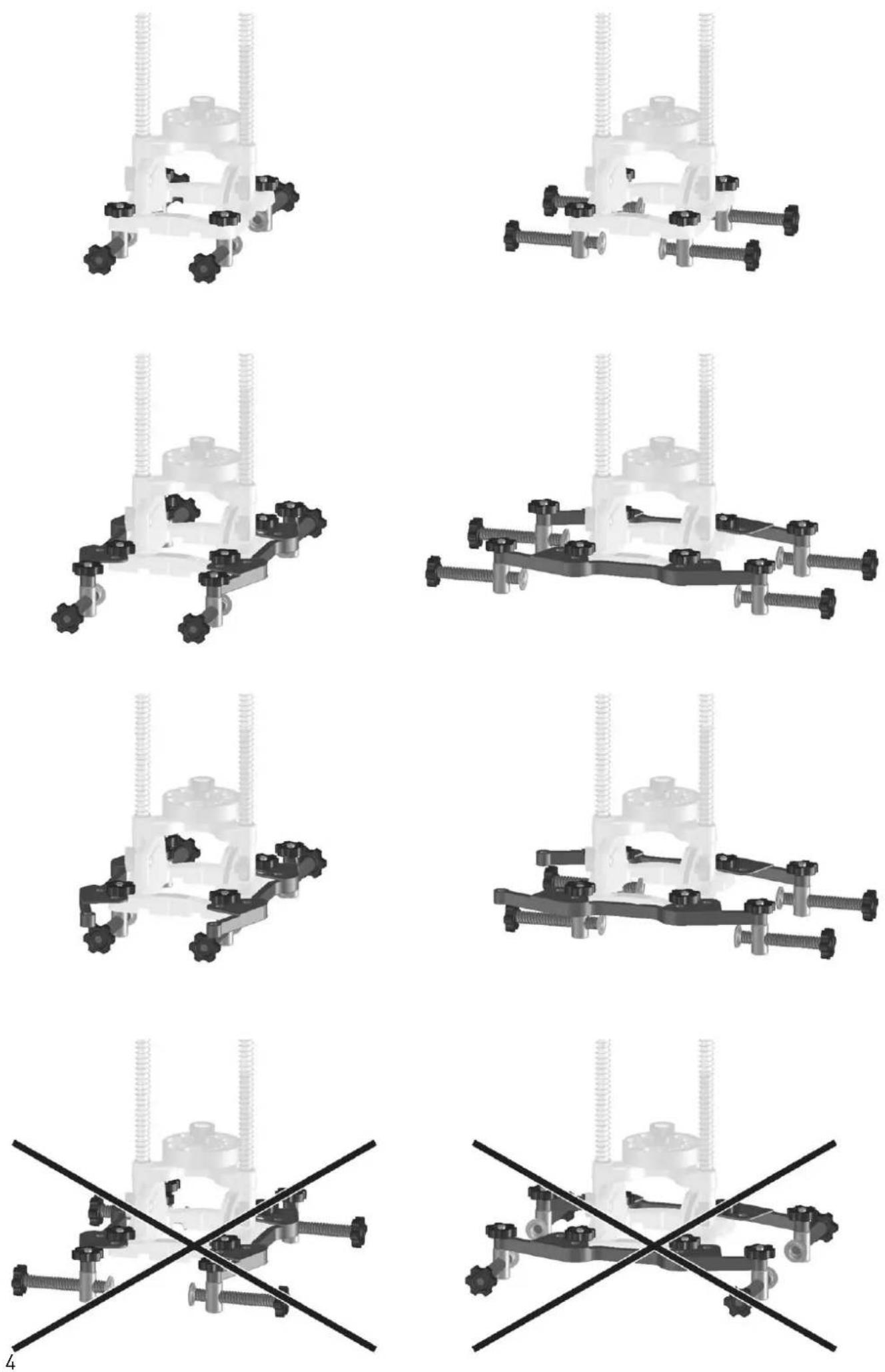
6.9 Clamping of the drilling stand
For the clamping of the stand upon the material, there serve the clamping elements (12). These can be fastened upon the base board (1).
▶ Insert the clamping element into the orifice
(1.4) from below, screw the clamping nut (12.1) upon it from above, and tighten it.
▶ By means of the screw (12.2), tighten it in the required position.
The clamping elements (not included in the scope of the delivery but accessories) are used always in pairs, from both the sides. We recommend employing four clamping elements.
For materials up to the maximum dimension of 300 mm, the clamping elements can be fastened on the bracket (13).
▶ Fit the screws (13.1) from below into the orifices in the base (1.4).
▶ Set the brackets upon the screws (13.1) from above, and tighten them with nuts (13.2).
The brackets (which are not included in the scope of the delivery, accessories) are offered in pairs (2 pcs). It is necessary to pay attention to the stand to be clamped on the beam between two clamps (12), situated on one bracket (the distribution of forces in the longitudinal sense of the bracket), not by means of two brackets (see the figure). The brackets have been designed in such a way that it might be possible to clamp them upon both the basic types of the stands (the vertical ones and the tilting ones) both in the longitudinal and the vertical directions.
7 Drilling
- Before you proceed to drilling, make sure that both the spiral drill and the drilling machine are well clamped.
- Check the stops and the guide disk, to see, whether they are set tightly, and if necessary, tighten the clamping elements.
- Do not work with blunt of damaged drills.
- During the drilling operation, hold the equipment always with both hands: one hand on the additional handle of the drilling stand, and the other hand on the handle and the switch of the drilling machine.
- The marking on the base board (1.2 and 1.3) serves for drilling with visual control according to the mark.
7.1 Guiding disk
For the spiral drills with even diameters, there is employed a guide disk which is included in the scope of the delivery. For the spiral drills with odd diameters, there is employed a guide disk with odd diameters, supplied as an accessory.
▶ For the replacement of the guide disk, unscrew the rotary button (3.1).
▶ Next, it is possible to remove the installed guide
disk and to install another one.
7.2 Drilling jobs without a guiding disk
For working with drills of a larger diameter than 27 mm (up to 45 mm as the maximum), the guide disk can be dismounted in compliance with the above procedure. According to necessity, it is possible to dismount also the springs (5), the stop tube (6) and the depth stops (7.1 and 7.2). In such a case, proceed with utmost care. In any case, we recommend employing the bottom stop ring (7.2) for protection against undesirable contact of the rotating parts with the material.
In particular, take care that the rotating parts of the drilling machine or the employed drills may not come into contact with the parts of the drilling stand.
8 Maintenance and care

Customer service and repair only through manufacturer or service workshops: Please find the nearest address at:
www.festool.com/Service

Use only original Festool spare parts!
Order No. at: www.festool.com/Service
- Maintain the clamping elements and the clamping points free of dust, dirt and fi lings.
- Using a rag, remove the dirt from the guide bars, and applying lubricating grease or machine oil upon them, make sure they can slide easily.
- Maintain the seating surfaces of the base board clean; in this way, you will guarantee the accuracy and precision of the angles of the orifices.
Respect the following rule:
- The chosen springs of the drilling stand are at a larger distance from the guide bars intentionally. This is no shortcoming; on the contrary, in this way, a better functioning of the springs is achieved. These springs allow for a lower resistance during the drilling
9 Environment
Do not throw the power tool in your household waste! Dispose of the machine, accessories and packaging at an environmentally-responsible recycling centre! Observe the valid national regulations.
Information on REACH:
www.festool.com/reach

- Technische Daten
- Symbols
- Intended use
- Safety Instructions
- Save all warnings and instructions for future reference.
- Machine features
- Bringing the Stand into Operation
- Adjustment of the guiding disk
- Clamping of the drill
- Clamping of the drilling machine
- Adjustment of the drilling depth
- Additional handle
- Drilling with a parallel guide
- Adjustment of the angle of inclination (GD 460 A)
- Correction of the stop position (GD 460 A)
- Clamping of the drilling stand
- Drilling
- Guiding disk
- Drilling jobs without a guiding disk
- Maintenance and care
- Respect the following rule:
- Environment
Brand : FESTOOL
Model : GD 320
Category : Drill