AMTRON Premium E 1122 T2 - Car charger Mennekes - Free user manual and instructions
Find the device manual for free AMTRON Premium E 1122 T2 Mennekes in PDF.

| Product type | Electric vehicle charging station |
| Brand | Mennekes |
| Model | AMTRON Premium E 1122 T2 |
| Dimensions (H x W x D) | 474 x 259 x 220 mm |
| Weight | 5 to 8.5 kg |
| Protection rating | IP44 (with cable), IP54 (with cover) |
| Protection class | II |
| Power supply | 230/400 V AC, 50 Hz, single-phase or three-phase |
| Rated current | 16 A or 32 A depending on configuration |
| Max. charging power | 3.7 / 7.4 / 11 / 22 kW |
| Main functions | Mode 3 charging, RFID, Wi-Fi/Ethernet connection, mobile app, energy management, tariff switching |
| Maintenance and cleaning | Daily visual check, half-yearly differential test, annual inspection by an electrician |
| Safety | Type B RCD, circuit breaker, phase monitoring, emergency unlocking |
| Spare parts and repairability | Mennekes original parts, technical support, software updates |
| General information | Stationary installation, indoor/outdoor, temperature -25°C to +40°C, max altitude 2000 m |
Frequently Asked Questions - AMTRON Premium E 1122 T2 Mennekes
User questions about AMTRON Premium E 1122 T2 Mennekes
0 question about this device. Answer the ones you know or ask your own.
Ask a new question about this device
Download the instructions for your Car charger in PDF format for free! Find your manual AMTRON Premium E 1122 T2 - Mennekes and take your electronic device back in hand. On this page are published all the documents necessary for the use of your device. AMTRON Premium E 1122 T2 by Mennekes.
USER MANUAL AMTRON Premium E 1122 T2 Mennekes
natural_image
Exterior view of a modern electric vehicle charging station with blue and silver cables against a concrete wall (no visible text or symbols)
Inhaltsverzeichnis
5. Installation....10
5.1 Standortwahl 10
6.4.4 Menü "Whitelist" 25
6.4.5 Menü "System" 27
6.5 Gerät prüfen 27
6.6 Zeitsynchronisation 28
6.6.1 Zeitsynchronisierung per MENNEKES Charge APP....28
6.7 MENNEKES Charge APP....28
natural_image
Two identical devices with blue and black cables, each labeled with a dimension (300, 300300) and an 'MONSTER' logo on top, placed on a flat surface (no text or symbols on devices themselves)natural_image
Illustration of a remote control unit emitting sound waves next to a desktop computer (no text or symbols)IP Adresse: 172.31.0.1
| Use Static IP Address | ☑ |
| Static IP Address | 192.168.178.222 |
| Static Netmask | 255.255.255.0 |
| Static Gateway Address | 192.168.178.1 |
Submit Changes
6.4.2 Menü "Installation Settings"
■ Ethernet IP Address
■ Ethernet Subnet Mask
■ Ethernet Gateway IP Address
■ Source of Ethernet IP Address
■ Ethernet MAC Address
■ Active WLAN Mode
■ Status Details
■ Broadcasting SSID
■ WLAN Channel
■ WLAN MAC Address
■ Connected Clients
■ WLAN IP Address
■ WLAN Subnet Mask
6.4.4 Menü "Whitelist"
6.7 MENNEKES Charge APP

https://www.chargeupyourday.com/

13. Glossar
1.2 Warning information....2
1.3 Symbols used....3
2. For your safety....3
2.1 Target groups....3
2.2 Intended use 3
2.3 Improper use....4
2.4 Basic safety information....4
2.4.1 Observance of local conditions ....4
2.4.2 Observing supervisory duties....4
2.4.3 Proper condition....4
3. Product description 5
3.1 Delivery content....5
3.2 Name Plate ....5
3.3 Device layout 6
3.4 Optional equipment....8
4. Technical data 9
5. Installation....10
5.1 Choice of location....10
5.2 Permitted environmental conditions....10
5.3 On-site installation....10
5.3.1 Supply line 11
5.3.2 Fuse protection....11
5.3.3 Routing supply, data and control cables ..... 11
5.4 Opening the device....12
5.5 Installing the device 12
5.5.1 Mounting distances....12
5.5.2 Wall mounting....12
5.6 Electrical connection....13
5.6.1 Connecting the supply line 13
5.6.2 Establishing network connection.... 13
5.6.3 Creating tariff-switching signal....14
5.6.4 Connection via RS-485 bus 15
5.7 Set up three-phase device for single-phase operation....15
5.8 Configuration switches....16
5.9 Closing the device....16
6. Start-up....17
6.1 Switching on the device....17
6.2 Monitoring power supply....17
6.3 Network connection....17
6.3.1 Setting up network connection....18
6.3.2 Integrating into the home network .....19
6.4 Configuring via the service interface.... 21
6.4.1 Menu "Production Settings" 21
6.4.2 Menu "Installation Settings" 22
6.4.3 Menu "User Settings" 23
6.4.4 Menu "Whitelist" 25
6.4.5 Menu "System" 27
6.5 Checking the device....27
6.6 Time synchronisation....28
6.6.1 Time synchronization via MENNEKES Charge APP....28
6.6.2 Time synchronization in the service interface ..... 28
6.7 MENNEKES Charge APP....28
6.7.1 Network connection with MENNEKES Charge APP....29
6.7.2 Connection to the device 30
7. Maintenance....30
8. Troubleshooting....31
8.1 Fault code 31
8.2 Spare Parts.... 33
8.3 Unlocking the charging plug 33
9. Taking out of service and dismantling 33
10. Storage 33
-
Disposal....34
-
Accessory....34
-
Glossary....34
1. About this document
The AMTRON ^® , hereafter referred to as “device”, is available in various variants. You can find the version of your device on the name plate. This document refers to the following variants of the device:
■ AMTRON Xtra
■ AMTRON Xtra E
■ AMTRON Xtra R
■ AMTRON Premium
■ AMTRON Premium E
■ AMTRON Premium R
■ AMTRON Premium W
This manual is exclusively designed for qualified electricians and gives instructions for safe operation. Instructions for operation and function explanations can be found in the operating manual.
Observe all additional documentation for the use of the device. Keep all documents for later reference and pass these on to the new operator.
The German version of this manual is the original manual. Manuals in other languages are translations of this original manual.
MENNEKES reserves the right to change the software with respect to the description in this manual. The functions described in this manual are based on AMTRON ^® software 1.10.
Copyright © 2019 MENNEKES Elektrotechnik GmbH & Co. KG
1.1 Service
If you have questions concerning the device, please contact MENNEKES or your responsible service partner. On our homepage in “Search for Partners” you will find further contacts in your country.
Use the form in "Contact" on for a direct contact to MENNEKES.
http://www.chargeupyourday.com
Please have the following information ready to hand for a quick processing:
■ Type designation / serial number (see name plate on the device)
At www.amtron.info you can always find the latest news, software updates, change logs, and frequently asked questions about AMTRON.
Have the serial number ready to hand.
Further information about electromobility can be found on our homepage in at "FAQ's" https://www.chargeupyourday.com/faqs/

1.2 Warning information
Warning of personal injury

This warning notice indicates imminent danger that will result in death or severe injuries.

This warning notice indicates a dangerous situation that may result in death or severe injuries.

This warning notice indicates a dangerous situation that can result in minor injuries.
Warning of material damage

This warning notice indicates a dangerous situation that may result in property damage.
1.3 Symbols used

Only a qualified electrician may carry out operations marked with this symbol.

This symbol indicates an important note.

The symbol indicates additional, useful information.
This symbol marks a prompt for action.
■ This symbol marks a listing.
→ This symbol is used to refer to another section in this manual.
This symbol is used to refer to another document.
This symbol is used to point out a result.
2. For your safety
2.1 Target groups
Electrician

As a qualified electrician, you have received recognised electrotechnical training. Based on this knowledge, you are authorised to carry out the electrotechnical work requested in this manual.
Requirements for qualified electricians:
■ Knowledge of general and special regulations pertaining to safety and accident prevention.
■ Knowledge of electrotechnical regulations.
■ Knowledge of national regulations.
■ Ability to identify risks and avoid possible hazards.
2.2 Intended use
The AMTRON ^® is a charging station for use in private and semi-public areas, such as private property, company car parks or depots, access to which is limited.
The device is used solely to charge electric vehicles.
■ Mode 3 charging according to IEC 61851-1.
■ Plugs and sockets according to IEC 62196.
The unit is intended for permanent installation and for indoor and outdoor use.
For Premium versions only: the device can be used as a single charging point or in a group of several devices with a back-end system. Several devices are connected via a MENNEKES ACU. An ACU is installed in the MENNEKES eMobility-Gateway and in a Smart charging column.
For Xtra versions only: the device can be used as a single charging point.
Legal requirements in some countries provide additional protection against electric shock. A possible additional protective measure can be the use of a shutter.
The device may only be operated taking into account all international and national regulations. Please observe the following international regulations or the respective national transposition:
IEC 61851-1
IEC 62196-1
IEC 60364-7-722
All instructions in this manual are to be carried out exclusively by a qualified electrician.
Read and observe these instructions as well as all additional documentation for the use of the device.
2.3 Improper use
Using the device is safe only when used as intended. Any other use and changes to the device is contrary to the regulations and therefore not permitted.
The operator is responsible for the proper and safe use. MENNEKES Elektrotechnik GmbH & Co. KG accepts no liability for any consequences arising from improper use of the device.
2.4 Basic safety information
2.4.1 Observance of local conditions
If the installation is not adapted to the local conditions (e.g. cable length of the supply line), this will impair the operational safety. This can seriously injure or kill people.
▶ Adapt the installation to the local conditions.
2.4.2 Observing supervisory duties
Persons, especially children, and animals who are not fully able to assess potential hazards pose a danger to themselves and others.
- Keep away from the device, charging cable, tools and packaging.
2.4.3 Proper condition
Damaged device
If the device is damaged or defective, has a defective housing or missing components, people can be seriously injured by electric shock.
▶ Avoid collisions and improper handling.
▶ Do not use the device in case of damage / defects.
▶ Mark a damaged device, so that other persons cannot use it.
▶ Eliminate damage immediately.
▶ Shut down the device if necessary.
Improper maintenance
Improper maintenance can affect the safety of the equipment and cause accidents. This can seriously injure or kill people.
▶ Observe the maintenance schedule.
- Carry out regular maintenance (twice a year or annually)
▶ Conclude maintenance contract if necessary.
3. Product description
The devices may differ due to customer or country-specific requirements. Depending on the model, the device may differ visually from the illustrations in this guide.
3.1 Delivery content
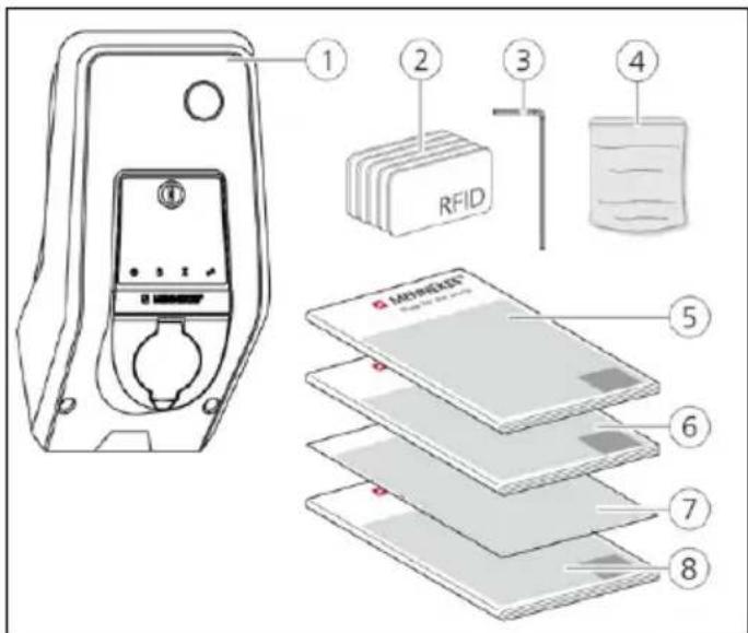
Fig.: 1. Delivery content
- Device
- RFID cards (2x master, 3x user)
- Hex wrench
- Bag with installation hardware (screws, dowels, sealing plugs)
- Operating manual
- Installation manual
- Set-up data sheet
- Drilling jig
^1) Optional

Without set-up data sheet, access to certain functions and the configuration is not possible.
▶ Keep the device data sheet in a safe place.
▶ Contact the MENNEKES support if you have lost it.
→ "1.1 Service"
The device can be used with or without MENNEKES
Charge APP. The MENNEKES Charge APP is not supplied. However, it is available free of charge in the App Store and the Google Play Store.
EN

MENNEKES recommend using the device with the MENNEKES Charge APP.
3.2 Name Plate
The name plate contains all important device data. The pictured name plate is a pattern.
▶ Note the name plate on your device. The name plate is installed on the housing base.
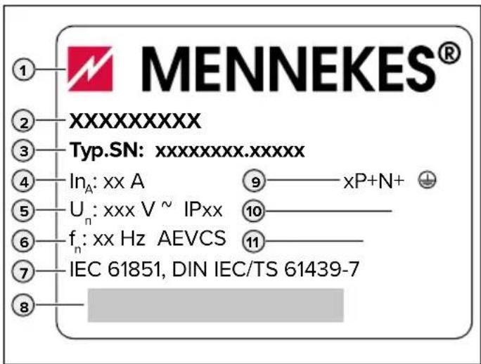
Fig.: 2. Name plate (pattern)
- Manufacturer
- Type
- Item / serial number
- Rated current
- Rated voltage
- Frequency
- Standard
- Barcode
- Number of phases
- Protection class
- Usage
3.3 Device layout
The enclosure of the device has three parts and consists of bottom part, top part and front panel.
The design of the front panel depends on the version of the device.
Front view
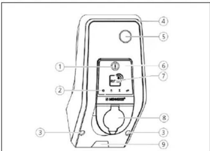
Fig.: 3. Front view (example: with type 2 charging socket for use with separate charging cable)
- Multi-function button 1)
- LED Info bar
- Fastening screws for upper housing part
- Upper enclosure section
- Energy meter with inspection window
- Front panel
- RFID card reader 1)
- Type 2 charging socket with hinged lid
- Pre-cut recess for supply cable / cable duct
1) Optional
Rear view
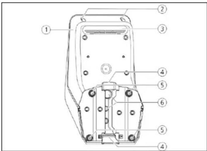
Fig.: 4. Rear view (example)
- Bottom part of enclosure
- Fastening screws for upper housing part
- Air outlet
- Recess for supply line / cable duct
- Fastening bores
- Cable glands
Interior view of front panel
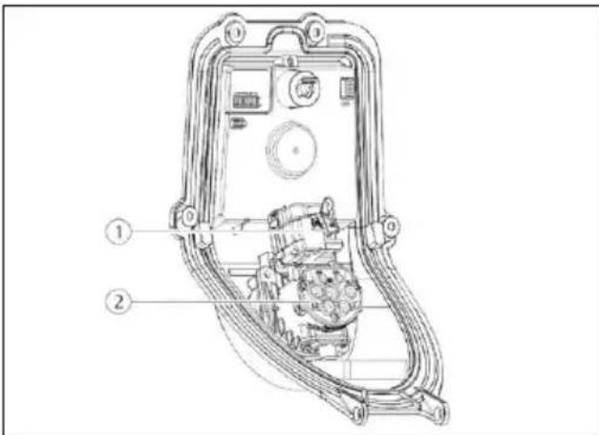
Fig.: 5. Interior view of front panel (example: with type 2 charging socket for use with separate charging cable)
- Actuator ^1) (plug interlock)
- Type 2 charging socket with shutter 1)
^1) Optional
Interior view of lower enclosure part
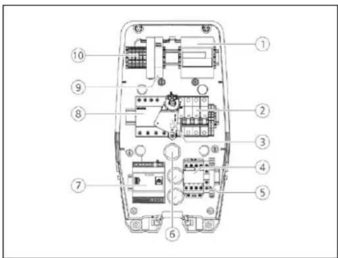
Fig.: 6. Interior view of lower enclosure part (example)
- Energy meter
- MCB (optional with shunt release) 1)
- Actuating element for multi-function button 1)
- Charging contactor point
- Phase sequence relay
- Cable glands
- Control (HCC 3)
- RCD 1)
- Power adapter
- Connection terminals for mains connection
^1) Optional
HCC 3
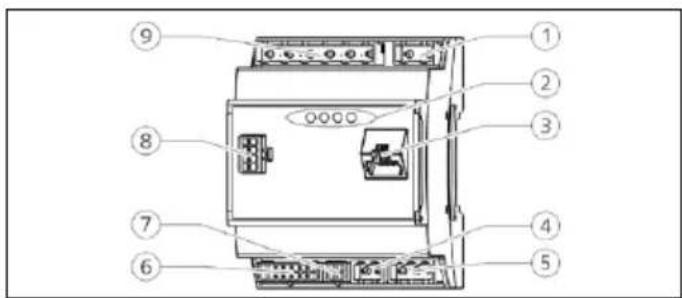
Fig.: 7. HCC 3 (example)
- Plug strip for tariff switching
- Status LEDs
- Network connection (RJ45)
- Plug strip, power supply 12 V DC
- Plug strip RS-485 bus
- Plug strip for charging socket
- Plug strip for S0 counter
- Plug strip for front panel
- Plug strip for low voltage signal 230 V AC
The HCC 3 provides five operating modes that can be changed even during operation depending on the configuration.

Operating manual AMTRON Xtra (E/R), Premium (E/R/W)
"5.1 Functional description of the operating modes"

The availability of operating modes and functions depends on the equipment and the configuration of the device. The configuration is carried out via an Internet browser in the service interface.
3.4 Optional equipment
| RFID card reader Fuse protection Control element | |||
| Premium E(EU version) | RFID card reader - Stop button | ||
| Xtra E(EU version) | -- Stop button | ||
| Premium R(EU version) | RFID card reader | Personal protection(RCD) | Multifunction button |
| Xtra R(EU version) | - | Personal protection(RCD) | Multifunction button |
| Premium W(EU version) | RFID card reader | Personal and circuit protection (RCD and MCB)with shunt release | Multifunction button |
| Premium(Version for Germany) | RFID card reader | Personal and circuit protection(RCD and MCB) | Multifunction button |
| Xtra(Version for Germany) | - | Personal and circuit protection(RCD and MCB) | Multifunction button |
- Technical data
| Charging power Mode 3 [kW] | 3.7 | 7.4 | 11 | 22 |
| Rated voltage UN [V] AC ±10 % | 230 230 400 400 | |||
| Rated frequency fN [Hz] | 50 | |||
| Rated current IHA [A] | 16 32 16 32 | |||
Maximum backup fuse [A] According to name plate / configuration
Protection class
■ Device with permanently connected charging cable: IP 44
■ Device with hinged lid: IP 54
Protection class II
Dimensions H × W × D [mm]
474 × 259 × 220
Weight [kg]
5 - 8.5
Rated insulation voltage U_i [V]
500
Rated impulse withstand voltage U_imp[kV]
4
Rated current of charging points circuit I_nC [A]
16, 1 ph
32, 1 ph
16, 3 ph
32, 3 ph
Rated conditional short-circuit current of charging points circuit I_cc [kA]
10
Rated diversity factor RDF
1
Pollution degree
3
Overvoltage category
|||
Types of system earthing
TN/TT
Installation
Outdoor or indoor
Stationary or movable
Stationary
Usage
AEVCS
External design
Wall mounted
EMC classification
A+B
Mechanical impact protection
IK10
Nominal cross-sectional area [mm ^4 ]
4 10
10
4 10
10
Terminals for supply line
rigid 3 × 6
rigid 3 × 10
rigid 5 × 6
rigid 5 × 10
flexible 3 × 4
flexible 3 × 6
flexible 5 × 4
flexible 5 × 6
Tightening torque: [Nm]
max. max.
max. 1.8
max. max.
1.8
max. 1.8
Standard
IEC 61851, DIN IEC / TS 61439-7
5. Installation
TENTION
Damage to the device by improper handling
Collisions and impacts as well as improper handling may damage the device.
▶ Avoid collisions and impacts.
▶ Use a soft base to set aside the device.
▶ Do not use the bolts for attaching the front panel as transport support or handle.
5.1 Choice of location
The unit is intended for permanent installation and for indoor and outdoor use. A suitable location meets the following requirements:
■ The device and the charging station are in sufficient proximity to each other, depending on the charging cable used.
■ Technical data and mains data are the same.
→ “4. Technical data”
■ Permissible ambient conditions are observed.
5.2 Permitted environmental conditions
ANGER
Danger of injury and fire.
If the device is operated in potentially explosive areas (ex areas), explosive substances may be ignited by sparking of device components.
▶ Do not use charging cable in potentially-explosive atmospheres (e.g. at gas filling stations)
TENTION
Device damage due to unsuitable ambient conditions
An unsuitable choice of location may cause damage to the device. Please note the following points when choosing a location:
- Avoid direct sunlight. If necessary, install the weather protection cover.
▶ Prevent penetration of water and heat build-up.
▶ Ensure adequate ventilation of the device. Do not install in niches.
▶ Keep device away from heat sources.
▶ Avoid strong temperature fluctuations.
Permitted environmental conditions
| Ambient temperature -25 ... +40 °C | |
| Average temperature over 24 hours | < 35 °C |
| Altitude Max. 2,000 m above sea level | |
| Relative humidity max. 95 % (non-condensing) | |
5.3 On-site installation
NGER
Fire hazard due to device overload.
There is a fire hazard due to overloading of the device caused by unsuitable circuit breaker and supply line.
▶ Route the supply line and the circuit breaker according to the technical data of the device.

The installation of a device in a supply grid in the disturbance sources e.g. a frequency converter can cause malfunction or termination of the charging process.
5.3.1 Supply line
▶ Design of the supply line according to the rated current.
→ "4. Technical data"
When dimensioning the supply line (cross section and cable type), always ensure the following local conditions:

■ Type of installation
■ Cable parameters per unit length
■ Line length
5.3.2 Fuse protection
Depending on the version, the device is equipped with a type B residual current circuit breaker (RCI) and a miniature circuit breaker (MCB) according to the table below.
| Version RCCB | type B | MCB |
| Xtra E, Premium E - - | ||
| Xtra R, Premium R X - | ||
| Xtra, Premium (W) X X |
Miniature circuit breaker (MCB)
For versions Xtra E, Xtra R, Premium E and Premium R, the miniature circuit breaker (MCB) must be provided on site.

The miniature circuit breakers must be dimensioned according to the specifications on the name plate, the required charging power, the supply line (line length, cable cross-section) to the device and national regulations.
Residual current circuit breaker (RCCB)
NGER
Risk of injury from electric shock
Residual current devices (type B) sensitive to universal currents may not installed behind residual current circuit devices (type A) sensitive to pulse currents. The type A trigger function can be affected by type B so that they cannot be switched off even if fault currents occur.
▶ Always connect a type B residual current device before a type A residual current device.

■ Devices without internal residual current device must be connected via a separate residual current device (see also IEC 60364-7-722).
■ Devices with integrated residual current device are supplied with type B.
■ No other circuits may be connected to this residual current device.
For the versions Xtra E and Premium E, the required residual current device must be provided by the customer.
5.3.3 Routing supply, data and control cables
▶ All necessary lines to the location shall be surface-mounted or concealed.
→ Notes regarding the pipelines:
"5.5 Installing the device" and "5.6 Electrical connection"
Surface installation

MENNEKES recommends mounting the device on an on-site cable duct
(height 30 mm × width 45 mm).
If cable or cable duct comes from below, you have to break out the pre-cut opening in the front enclosure part.
Concealed installation
In a concealed installation of wires, their positions must be arranged in accordance with the drilling jig.
5.4 Opening the device
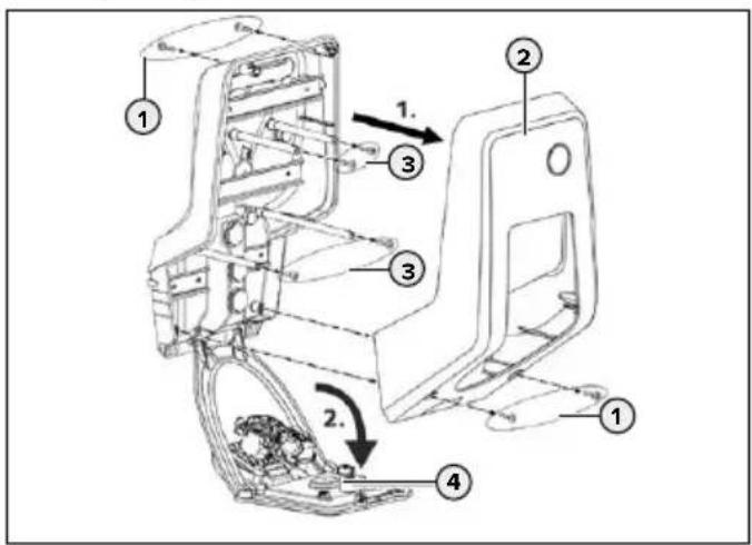
Fig.: 8. Opening the device
When delivered, the front enclosure part (2) is not attached with screws. The screws (1) are stored in the enclosed accessory bag.
▶ Ensure that the power supply is switched off.
▶ Remove the upper enclosure part (2).
▶ Remove screws (3) of front panel and fold down front panel (4).
5.5 Installing the device

At strong minus temperatures, the device should be initially stored for 24 hours at room temperature before installation and commissioning.
5.5.1 Mounting distances
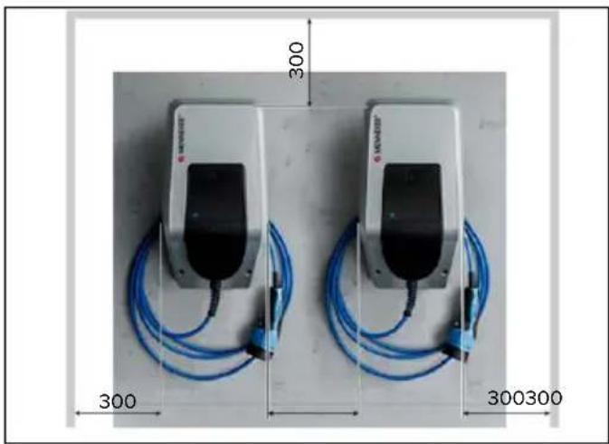
natural_image
Two identical devices with blue cables and connectors, each labeled with dimensions (300, 300, 300) and a small 'MONSTER' logo on top.Fig.: 9. Mounting distances [mm]
The specified mounting distances are minimum distances for unrestricted access during operation, maintenance and repair.
5.5.2 Wall mounting

MENNEKES recommends mounting at an ergonomically sensible height depending on the height of the body.
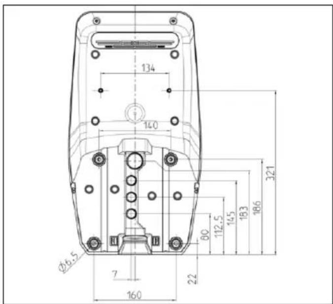
Fig.: 10. Drilling dimensions [mm]
Mark the mounting holes using the supplied drilling jig or „Fig.: 10. Drilling dimensions“.
i
For installation on concrete, brick and wood walls, use the included installation hardware. For other surfaces, a suitable on-site mounting method must be chosen.
▶ Drill holes in the wall with the diameter required by selected mounting material.
▶ Route cables to the positions indicated on the drilling jig.
i
Approx. 45 cm of cable are required for the supply line inside the device.
▶ Insert cables through one of the cable entries in the device. To do this, you need a hole in the respective membrane.
i
To prevent the ingress of rainwater, the hole in the membrane should not be larger than the pipes.
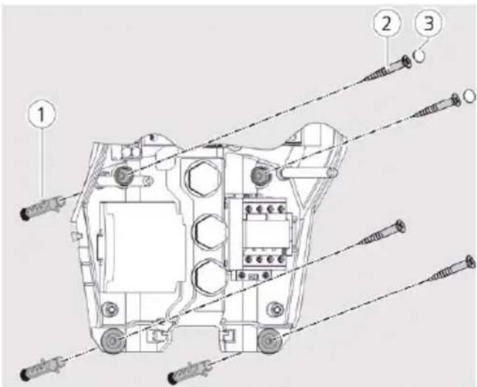
Fig.: 11. Attach to the wall
▶ Screw the unit to the wall using dowels (1), screws (2) and plugs (3).
▶ Check the device for firm and secure attachment.
5.6 Electrical connection
5.6.1 Connecting the supply line
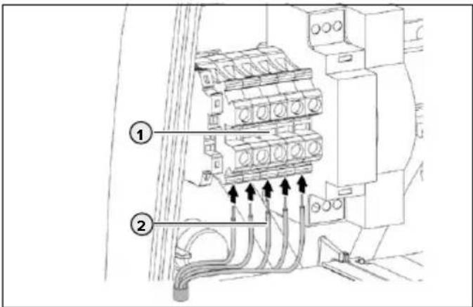
Fig.: 12. Terminals
▶ Strip 370 mm supply line.
▶ Strip 12 mm core insulation.
▶ Connect the cable cores (2) to the terminal block (1) according to the circuit diagram.
i
When routing the supply line, observe the permissible bending radius.
▶ Check that the individual cores are properly connected and the screws tightened.
5.6.2 Establishing network connection
The device can be integrated into a home network wirelessly over WLAN or wired over an Ethernet cable (RJ45).
Wireless networking
Wireless networking is possible if the device is within range of your Wi-Fi network. No need for additional wiring is required.
Wired networking
If the device should be integrated into the network via Ethernet, a suitable network cable with RJ45 plug must be routed to the device.
The network cable must have sufficient dielectric strength and be suitable for common routing with live conductors.

MENNEKES recommends using Ethernet cables cat. type 7a or higher.
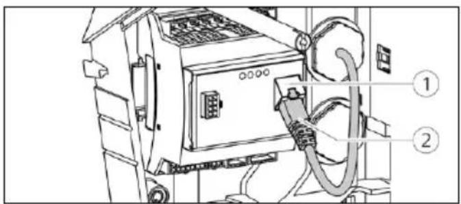
Fig.: 13. Connecting network cable
▶ Make sure that the bending radius of the network cable used is not too low.
▶ Connect the plug (2) of the network cable to the network socket of the HCC 3s (1).
5.6.3 Creating tariff-switching signal
For operating the device in mode “network control”, the device must be connected to, for example, a ripple control receiver.
The tariff-switching signal is connected to the HCC 3 with a connector.
■ To activate the off-peak tariff (NT), the tariff-switching signal must be present at the input of the HCC 3s.
If the main tariff (HT) is active, no tariff-switching signal must be present at the input of the HCC 3s.
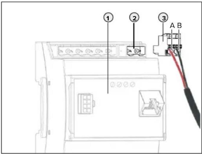
Fig.: 14. Connect tariff-switching signal
▶ Strip the control line.
▶ Connect phase to terminal A and neutral conductor to terminal B of the plug connector (2).
Terminals Description
A Phase for tariff-switching signal 230 V AC
B Neutral conductor for tariff-switching signal 230 V AC
▶ Insert the plug connector into the corresponding connector strip (2) on the HCC 3 (1).
- Connecting the external device according to the manufacturer's instructions.

When connecting the tariff-switching signal to an external voltage source, a note conforming to national regulations must be attached (e.g. in form of a sticker).
The activation of the tariff-switching signal is carried out in the service interface.
The maximum available current for main tariff and off-peak tariff is set in the MENNEKES Charge App.
5.6.4 Connection via RS-485 bus
If several devices are controlled via a higher-level backend system e.g. chargecloud, the devices must be connected via an RS-485 bus with a MENNEKES ACU. The bus cable is connected to the HCC 3 via a supplied connector with double connection.

To control multiple devices, the wiring must be located in line bus topology.

MENNEKES recommends the following cables for the RS-485 bus:
■ For installation in the ground: Siemens PROFIBUS line, underground cable 6XV1830-3FH10 (manufacturer EAN 4019169400428).
■ For installation without mechanical stress: Siemens PROFIBUS line 6XV1830-0EH10 (manufacturer EAN 4019169400312).
When using the recommended cables, trouble free operation at bus lengths up to 300 metres can be expected.
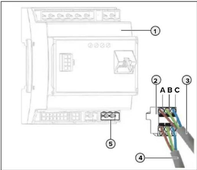
Fig.: 15. Connection of the RS-485 bus
▶ Strip the bus line (3) of the previous ACU or SCU and expose the shields.
▶ Connect shields from (3) to terminal C of the connector with double connection (2).
▶ Connect single cores from (3) to terminals A and B (example for Siemens Profibus cable: green wire to terminal A, red wire to terminal B, gray wire to terminal C).
Terminal Description
A Bus signal A
B Bus signal B
C Reference level
▶ Connect the bus line of the following SCU (4) analogously to (3).
▶ Insert the plug connector (2) into the corresponding plug strip (5) on the HCC 3 (1).
▶ Connect to the previous or subsequent ACU or SCU in the same way.
5.7 Set up three-phase device for single-phase operation
For single-phase operation of a three-phase device (for devices with 11 or 22 kW charging power), the potentiometer at the phase sequence relay must be changed.
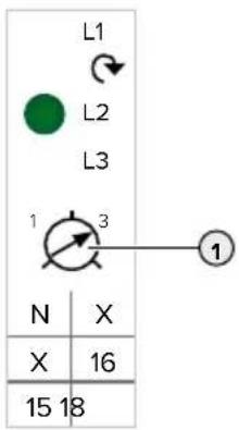
▶ Connect the device to single phase.
To do this, use the terminals L1, N and PE.
▶ Adjust potentiometer (1) to position 1 using a slotted screwdriver.
Tick checkbox "Monitoring Relay Wired to 1 Phase Only" in service interface.
→ "6.4.2 Menu "Installation Settings"
Setting Description
1 Single-phase operation
3 Three-phase operation
5.8 Configuration switches
Only with AMTRON ^® software 1.10 and higher.
You can use the configuration switch S1 to change to the operating mode „SCU“. The configuration switches S2, S3, S4, S5, S6, S7 and S8 are not assigned. The configuration switches are on the rear side of the front panel.
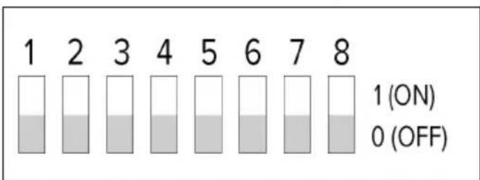
Fig.: 16. Configuration switches
Setting Description
S1 = 1 (ON) Operating mode "SCU" is active.
S1 = 0 (OFF) Operating mode "SCU" is not active.

If the operating mode "SCU" is activated via the configuration switch, another operating mode set in the service interface is ignored.
If the configuration switch is reset to the position S1 = 0 (OFF), the previously set operating mode becomes active again.
Set permanent operation in „SCU“ mode
▶ Set operating mode „SCU“ in the service interface.
→ „6.4.3 Menu “User Settings”“
▶ Restart the device.

If the operating mode "SCU" is set in the service interface, the operating mode "SCU" will always remain active even when switching the configuration switch S1 on or off.
5.9 Closing the device
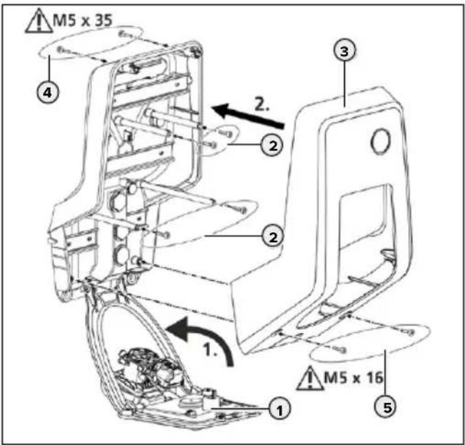
Fig.: 17. Closing the device
▶ Lift the front panel (1) upwards and secure it with the screws (2).
▶ Fit the upper part of the enclosure (3) and secure it with the screws (4) and (5). Use supplied shortened Allen key.
6. Start-up
6.1 Switching on the device
NGER
Electric shock hazard when devices are damaged
Use of a damaged device may result in electric shock.
▶ Do not use the device if it is damaged.
▶ Mark the damaged device to ensure that no one continues using it.
▶ Have a qualified electrician rectify the damage immediately.
▶ Have an electrician take the device out of service if necessary.
Precondition:
■ Device is installed correctly.
■ Device is in a proper condition.
▶ Switch on the RCD and MCB.
▶ Switch on the power supply and check.
→ "6.2 Monitoring power supply"
LED on the power supply is on.
The "Ready for operation" LED on the LED info field lights up.
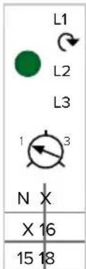
6.2 Monitoring power supply
The device is monitored by a phase sequence relay. It checks the three phases (L1, L2, L3) and the neutral conductor (N) of the power supply for correct phase sequence, phase failure or undervoltage.
Operating status display
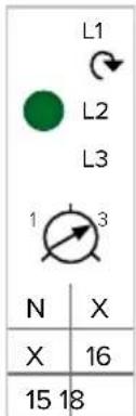
Three phases, clockwise field of rotation:
▶ Using terminals L1, L2, L3, N, PE.
▶ Setting relay potentiometer to 3.
The green LED is lit.
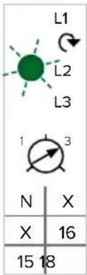
Three phases, anti-clockwise field of rotation:
▶ Using terminals L1, L2, L3, N, PE.
▶ Setting relay potentiometer to 3.
The green LED is flashing.
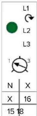
One phase:
▶ Using terminals L1, N, PE.
▶ Setting relay potentiometer to 1.
The green LED is lit.
The potentiometer is only evaluated once after applying the supply voltage.
6.3 Network connection
If the network connection is established, the device can be configured and used. Functions and modes are configured with an Internet browser via the service interface of the device. The device can be operated with a mobile terminal via the MENNEKES Charge APP.
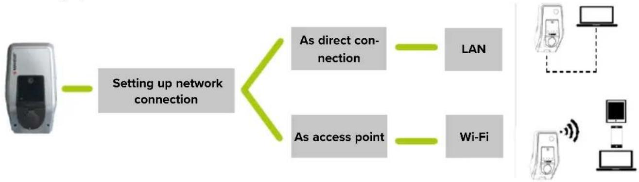
6.3.1 Setting up network connection
flowchart
graph TD
    A["Device"] --> B["Setting up network connection"]
    B --> C["As direct connection"]
    B --> D["As access point"]
    C --> E["LAN"]
    D --> F["Wi-Fi"]
    G["Computer"] --> H["Data Tower"]
    I["Desktop Computer"] --> J["Wireless Device"]
The network connection is established either as a direct connection with a LAN cable or as an access point via the WLAN of the device.
Direct connection
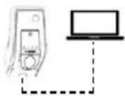
In order to establish a direct connection via LAN, the device and the terminal device (PC / laptop) must be in the same address area. The IP address of the device is static when the connection is direct.
IP address: 192.168.0.100
▶ Connect the device and the terminal with a LAN cable.
▶ Change the properties of the network connection at the terminal:
IPv4 address: 192.168.0.21
IPv4 subnet mask: 255.255.255.0
▶ Open the Internet browser. The service interface can be reached at http://192.168.0.100:25000.
As access point
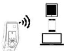
natural_image
Diagram showing a device with wireless signal and a separate device with a monitor and laptop (no text or symbols)When delivered, the internal WLAN module operates as an access point. This means that the device makes its own WLAN network available, with which the terminal (PC / laptop / tablet / smartphone) can be connected.
IP address: 172.31.0.1
The WLAN of the device is secured with WPA2 encryption.
▶ Activate WLAN on the terminal.
▶ Connect the terminal to the WLAN network of the device.
To do this, enter the WLAN WPA2 key (setup data sheet).
▶ Open the Internet browser. The service interface can be reached at http://172.31.0.1:25000 or at http://myamtron.com:25000.

The access point is always active if the device has not been integrated with WLAN in a home network or if no WLAN network is available.
6.3.2 Integrating into the home network
If necessary, the device can be integrated into the home network to access the service interface and the MENNEKES Charge APP at any time without further configuration. This allows configuration or operation of the device despite distance.
The integration of the device is carried out either via LAN or via WLAN. The router assigns the device a dynamic IP address by default. If necessary, the a static IP address can be assigned to the device.
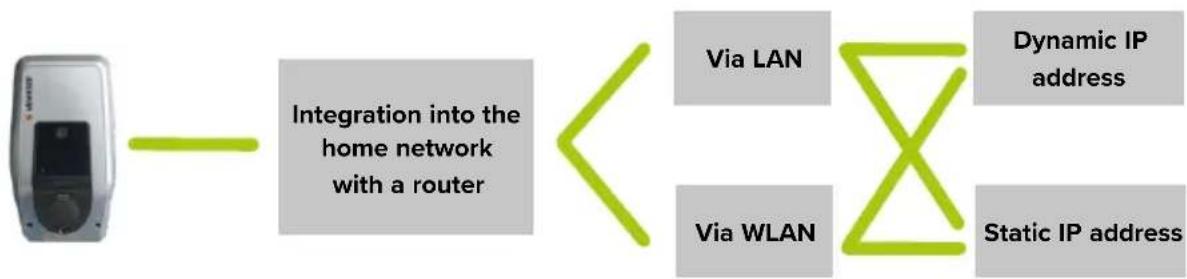
flowchart
graph LR
    A["Mobile Device"] --> B["Integration into the home network with a router"]
    B <--> C["Via LAN"]
    B <--> D["Via WLAN"]
    C --> E["Dynamic IP address"]
    D --> F["Static IP address"]
EN
Via LAN
▶ Connect the device and router with a LAN cable. No further configuration is necessary.
The service interface can be reached at http://AMTRONIP:25000 (enter the IP address of the device instead of "AMTRONIP"). The device receives its dynamic IP address via the DHCP function of the router, which may change depending on the configuration of the router.
The assigned IP address can be retrieved in the user interface of the router.
Operating instructions of the router.
Via WLAN
In order to integrate the device into the home network via WLAN, a previous configuration is necessary.
▶ Establish connection to the service interface.
→ "6.3.1 Setting up network connection"
In the service interface, navigate to "User Settings" > "WLAN STA/Client Mode Settings".
▶ Enter the name of the WLAN in the "Network Name/SSID" field.
▶ Enter the WLAN password in the "WLAN Key" field.
▶ If necessary, select in the "Security Mode" field, the encryption system of the router.
By default, the encryption system is detected automatically. If this is not the case, select the encryption system used by the router in "Security Mode".
▶ Confirm with "Submit".

As soon as the input has been confirmed with "Submit", the device receives its IP address from the DHCP function of the router. The service interface is no longer available at the current address.
During the connection, the service interface can be reached at http://AMTRONIP:25000 (instead of "AMTRONIP" enter the IP address of the device).
The device receives its dynamic IP address via the DHCP function of the router and can change depending on the configuration of the router.
The assigned IP address can be retrieved in the user interface of the router.

Operating instructions of the router.

If the device loses the WLAN connection to the network, the access point is activated automatically.
Assign static IP address
If necessary, the a static IP address can be assigned to the device. The IP address does not change.
For LAN connection:
▶ Navigate to "User Settings"> "Ethernet Settings" in the service interface.
For WLAN connection
In the service interface, navigate to "User Settings" > "WLAN STA/Client Mode Settings".
▶ Activate the "Use static IP" field.
In the "Static IP Address" field, enter the desired IP address.

The static IP address is selected depending on the router.
Precondition:
■ Router and device are in the same address area.
■ The last three numbers of the IP address should be greater than 200. Numbers up to 200 are often reserved for the DHCP function of the router.
▶ Enter the subnet in the "Static Netmask" field.
▶ Enter the IP address of the router in the "Gateway Address" field.

Operating instructions of the router.
▶ Confirm with "Submit".
During the connection with a static IP address, the service interface can always be reached at http://AMTRONSTATICIP:25000 (enter the static IP address of the device instead of "AMTRONSTATICIP").
Example:
Settings in the service interface when assigning a static IP address (connection to LAN). The router is FRITZ!Box with the default IP address 192.168.178.1
Ethernet Settings
| Use Static IP Address | ☑ |
| Static IP Address | 192.168.178.222 |
| Static Netmask | 255.255.255.0 |
| Static Gateway Address | 192.168.178.1 |
Submit Changes
Fig.: 18. Settings in the service interface when assigning a static IP address (connection to LAN). The router is Fritz!Box.
In case of the settings in the example, the service interface can always be reached at http://192.168.178.222:25000.
6.4 Configuring via the service interface
Requirements for Internet browsers:
■ JavaScript activated
■ Microsoft Internet Explorer 11 or higher
■ Mozilla Firefox v30 or higher
■ Google Chrome v35 or higher
■ Opera v20 or higher
▶ Enter the IP address of the device and port (25000) in the address bar of your Internet browser.
→ "6.3 Network connection"
▶ Enter PIN3 (installation PIN).
The main menu of the service interface opens.

When entering the PIN1 (APP PIN), no changes in the "Installation Settings" menu are possible.
▶ Synchronize time.
→ "6.6 Time synchronisation"

A fault message appears on the LED information field if the time is not synchronized.
The following submenus are displayed:
■ "Production Settings": display of the manufacturer settings and hardware / software versions.
■ "Installation Settings": making settings for commissioning.
■ "User Settings": making customer-specific settings.
■ "Whitelist": defining RFID cards (users).
■ "System": backup of the settings made, restarting the device, updating the software.
▶ Configure the device taking into account the circumstances and customer requirements.
▶ Save the set configuration by clicking the "Submit" button.
6.4.1 Menu "Production Settings"
The menu "Production Settings" displays factory settings and the hardware / software versions. You cannot make any changes here.
| Wallbox Data | |
| VALUE Description | |
| HMI HW Version Hardware version HMI | |
| HMI SW Version Software version HMI | |
| HMI Type HMI type | |
| HMI IO Status Status of inputs and outputs | |
| HMI Temperature Internal [°C] | HMI temperature |
| HMI Temperature External [°C] | Device temperature |
| HMI Error Code | HMI error code |
| RFID Version | Version of the RFID card reader |
| WLAN Version | Version of the WLAN module |
| HCC3 HW Version | Hardware version of the HCC 3 |
| HCC3 SW Version | Software version of the HCC 3 |
| HCC3 IO State | Status of the inputs and outputs of the HCC 3 |
| HCC3 CP/PP State | Status of CP/PP signal contacts |
| HCC3 Error Code | Error code of the HCC 3 |
| AMTRON Operation Mode | Operating mode of the deviceOperating manual AMTRON Xtra (E/R), Premium (E/R/W) “5.1 Functional description of the operating modes” |
| AMTRON name | Name of the device |
| AMTRON NDN | Network devices name |
| AMTRON State | Operating status of the device |
| AMTRON RS485 Address | Network address of the device with active RS-485 bus connection (SCU mode) |
| AMTRON Connector Type | Plug-in system of the device |
| AMTRON No. of Phases | Number of mains phases |
| AMTRON Rated Current | Maximum charging current |
| AMTRON Serial Number | Serial number of the device |
| AMTRON Order Number | Article number of the device |
| AMTRON Temperature Sensor Installed | ■ yes: Internal temperature sensor available■ no: Internal temperature sensor not available |
| AMTRON Local Fuses Installed | ■ yes: Internal RCD and MCB available■ no: Internal RCD and MCB not available |
| AMTRON Production Settings Write Enabled | ■ yes: “Production Settings” read-only■ no: “Production Settings” edit-able |
| HCC3 Ethernet MAC Address | MAC address of the LAN interface of the HCC 3 |
| HCC3 Total Energy [Wh] | Sum of the charged energy |
6.4.2 Menu "Installation Settings"
The menu "Installation Settings" can be used for the commissioning settings.
▶ Make adjustments taking into account the installation.
→ "5.3 On-site installation"
| Installation Data | |
| VALUE Description | |
| AMTRON Installation Current | Input: Maximum charging current in A |
| Energy Manager Present | ☐ Do not use Energy Manager ☑ Use Energy Manager ▶ If an Energy Manager is to be used, additionally select the desired Energy Manager in “Energy Manager Configuration”. |
| External Tariff Switch Connected | ☐ No external tariff-switching signal available☑ External tariff-switching signal available☑ Operating manual AMTRON Xtra (E/R), Premium (E/R/W) “5.1 Functional description of the operating modes” |
| Monitoring Relay Wired to 1 Phase Only | ☐ Monitoring of all three phases (for devices operated in three phases)☑ Monitoring of one phase (for devices operated in single phase) |
Information on "AMTRON Installation Current"
Devices with 3.7 kW charging power without miniature circuit breaker can be configured to 7.4 kW charging power.
▶ Set the “AMTRON Installation Current” field to 32 A.
NGER
Fire hazard due to device overload.
The is a fire hazard due to overloading of the device caused by unsuitable circuit breaker and supply line.
▶ Route the supply line and the circuit breaker according to the technical data of the device.
→ "5.3 On-site installation"
i Charging with 7.4 kW charging power is only possible with a charging cable designed for 32 A.
| Energy Management Configuration | |
| VALUE Description | |
| Energy Manager Protocol | Selection: log when using an Energy Manager■ Simple Energy Management Protocol (SEMP)■ Energy Control Interface (ECI) |
6.4.3 Menu "User Settings"
The menu "User Settings" can be used to make customer-specific settings.
| Wallbox Configuration | |
| VALUE Description | |
| AMTRONCustomerCurrentLimitation | Input: Setting the limit of the maximum available charging current in A. |
| AMTRONWallbox Name | Input: Device name.The device name is displayed in the MENNEKES Charge APP and the service interface. |
| Enable RFIDAuthorisation | ☑ RFID card reader activated☐ RFID card reader deactivated |
| Power FailContinue | ☑ Charging will continue after a power failure☐ Charging stops after a power failure |
| AutostartCharging | ☑ The charging process starts automatically when connected to a vehicle☐ The charging process must be started manually when connected to a vehicleThis setting is not taken into account if the RFID card reader is activated. |
| Enable StopButton | ☑ Stop button activated☐ Stop button disabled |
| Color Schema Input: colour scheme at the LED information field | |
| Enable RFID Beep | ☑ Acoustic feedback of the RFID card reader activated☐ Acoustic feedback of the RFID card reader deactivated |
| Enable WLAN Communication | ☑ WLAN module activated☐ WLAN module deactivated |
| AMTRON Operation Mode | Selection: Operating mode of the device |
The submenu "Wallbox Date and Time Configuration" can be used to set the date and the time.
■ The data of the Internet browser is accepted in "Alignment with Browser Time".
In "Manual Configuration" the data must be entered manually.
Electro Vehicle Data
Only configurable if no RFID card reader is activated / present or the operating mode "SCU" is active. Otherwise, the function can be set in the "Whitelist" menu.
VALUE Description
| No. of Vehicle Phases | Selection: Number of phases with which the vehicle charges |
| Minimum Current per Phase | Selection: Minimum charging current per phase, which the vehicle needs for charging |
| Maximum Current per Phase | Selection: Maximum charging current per phase, which the vehicle needs for charging |
| EV Wake-Up ☑ | Wake-up function activated☐ Wake-up function deactivatedIf the wake-up function is activated, older vehicles can be switched from standby mode to continue charging. Some vehicles may respond incorrectly to the wake-up signal. MENNEKES it is not liable for the correct reaction on the vehicle side. |
Integration into the home network via LAN
| Ethernet Settings | |
| VALUE Description | |
| Use Static IP Address | Use static IP addressDo not use static IP address |
| Static IP Address | Input: Static IP address |
| Static Netmask | Input: static network address |
| Static Gateway Address | Input: IP address of the router |
The following data is displayed in the submenu "Ethernet Status":
■ Ethernet IP Address
■ Ethernet Subnet Mask
■ Ethernet Gateway IP Address
■ Source of Ethernet IP Address
■ Ethernet MAC Address
Network connection through access point
| WLAN Access Point Mode Settings | |
| Value Description | |
| Network Name / SSID | Input: Network name of the WLAN that the device makes available |
| Channel Selection: | WLAN channel during the operation of the device as an access point |
| Security Mode Selection: | WLAN encryption. |
| Country of Operation | Selection: Country in which the device is operated |
Integration into the home network via WLAN
| WLAN STA/Client Mode Settings | |
| Value Description | |
| Network Name / SSID | Input: Name of the home network |
| WLAN Key Input: WLAN password | |
| Access Point BSSID (optional) | If several WLAN access points are available, the device switches between the access points depending on the reception. You can optionally enter the BSSID of the access point here to assign a fixed access point to the device |
| Security Mode Selection: WLAN encryption. | |
| Use Static IP Address | Use static IP addressDo not use static IP address |
| Static IP Address | Input: Static IP address |
| Static Netmask Input: static network address | |
| Static Gateway Address | Input: IP address of the router |
The following data is displayed in the submenu "WLAN Status":
■ Active WLAN Mode
■ Status Details
■ Broadcasting SSID
■ WLAN Channel
■ WLAN MAC Address
■ Connected Clients
■ WLAN IP Address
■ WLAN Subnet Mask
6.4.4 Menu "Whitelist"

The "Whitelist" menu is only displayed if an RFID card reader is present in the device (in the versions Premium (E/R/W)).
EN
The whitelist entries for the RFID cards can be edited, added or deleted in the "Whitelist" menu. The whitelist can be exported or imported.
▶ Enter PIN3 (whitelist PIN).
Adding an RFID card
In the "Whitelist" menu, select the submenu "Export".
| General data | |
| Value Description | |
| Card Name | Input: Desired name of the RFID card |
| Unique ID | Input: Number of the RFID cardIf the number of the RFID card is not known, it can be read out via a card reader. |
| Master ☑ | RFID card is a master RFID card☐ RFID card is not a master RFID card |
| Optional DataThis data is only taken into account in the mode “Energy Manager”. | |
| VALUE Description | |
| Vehicle Phases | Input: Number of phases of the vehicle. |
| Min. Current per Phase | Input: Minimum charging current per phase |
| Max. Current per Phase | Input: Maximum charging current per phase |
Value Description
EV Wake-Up ☑ Wake-up function activated
□ Wake-up function deactivated If the wake-up function is activated, older vehicles can be switched from standby mode to continue charging.

Some vehicles may respond incorrectly to the wake-up signal. MENNEKES it is not liable for the correct reaction on the vehicle side.
Deleting an RFID card
The “Whitelist” menu displays a list of already created RFID cards. Here the cards can be deleted.
▶ To delete the RFID card from the whitelist, click on the "Delete" button

The device necessarily requires two RFID cards taught as masters.
If a master RFID card is deleted via the service interface or the MENNEKES Charge APP, the next unknown RFID card held in front of the RFID card reader is automatically taught as a master.
Editing an RFID card entry
The “Whitelist” menu displays a list of already created RFID cards. Here you can edit the entries.
▶ Click on the "Edit" button to edit an entry
Exporting whitelist
In the "Whitelist" menu, select the submenu "Export".
Click on the "Export Whitelist as Excel CSV" button.
▶ Select the desired storage location.
Import whitelist
In the "Whitelist" menu, select the "Import" submenu.
- Click the "Browse" button and select the desired CSV file.
- Click the “Overwrite Whitelist from Excel CSV” button to override the current whitelist.
6.4.5 Menu "System"
| VALUE Description | |
| Backup Settings | Perform a backup of the settings made. The settings in “Installation Data”, “Production Settings” and “User Settings” (except “Wallbox Date and Time Configuration”) are saved and the backup file is downloaded. |
| Download System Logfile | Download a log file. This is designed for fault finding and can only be read by MENNEKES. |
| Restore Data from Backup | Upload the file downloaded in “Backup Settings”. The settings saved in the file are applied. [21C] The IP settings and the name of the device are overwritten when restoring a backup. This may cause an IP address conflict after the restart. ▶ Disconnect the device from the network and reset the IP address and the name.  To speed up initial installation of multiple AMTRONs with the same settings, use a (master) backup with activated DHCP. After restoring, configure the network settings of the AMTRONs on each device individually. To speed up initial installation of multiple AMTRONs with the same settings, use a (master) backup with activated DHCP. After restoring, configure the network settings of the AMTRONs on each device individually. |
| Firmware Update | Upload the current operating software of the device |
| Reboot Restart the device | |
Procedure "Firmware Update"
The current operating software can be downloaded at www.AMTRON.info.
▶ Enter the address www.AMTRON.info into the address EN bar of your Internet browser.
▶ Enter the serial number of your device in the input field "Access".
In the "Download" section, select the "Software Update" button
▶ Download and save the current software (name e.g. HCC3Application.bin)
In the service interface to "System" > "Firmware Update"
▶ Select the downloaded operating software.
- Click on the button "Update AMTRON" to update the software.
▶ Follow the instructions.
▶ Disconnect the device from the mains for three minutes and restart it.

If the update is interrupted prematurely (e.g. due to power failure), the device must be restarted (e.g. by the "Reboot" button) before a new update can be attempted.
6.5 Checking the device
Test according to IEC 60364 (in Germany according to DIN VDE 0100) as well as national regulations
During the first commissioning and in the specified maintenance intervals, carry out a test of the charging station in accordance with IEC 60364 (in Germany in accordance with DIN VDE 0100) and the respective applicable national regulations. The test can be carried out in connection with the MENNEKES test box and a standard-compliant test equipment. The MENNEKES test box simulates vehicle communication. Test boxes are available as accessories from MENNEKES.
▶ Perform a standard test before the device release.
Operating instructions of the test box.
6.6 Time synchronisation
During the initial setting-up process and after a power failure of more than four hours, a clock synchronisation is necessary.
The time synchronization can be carried out via
MENNEKES Charge APP or via the service interface.
6.6.1 Time synchronization via MENNEKES Charge APP
Time synchronisation with smart phone / tablet over the charge app takes place automatically as soon as a connection to the MENNEKES Charge APP has been established.
There is no need for further action.
6.6.2 Time synchronization in the service interface
The time synchronization is carried out in the service interface in "User Settings" > "Wallbox Date and Time Configuration".
■ The data of the Internet browser is accepted in "Alignment with Browser Time".
In "Manual Configuration", the data is entered manually.

The “Timezone Offset” is the difference between the local time zone and the Coordinated Universal Time (UTC) in minutes.
Example for Germany and Central Europe
The deviation of the local time zone from UTC is 1 hour, so the “Timezone Offset” parameter must be set to 60 minutes.
6.7 MENNEKES Charge APP

You cannot use the device with the MENNEKES Charge APP in "SCU" mode.
The device is operated with a mobile device (smartphone, tablet) via the MENNEKES Charge APP. You can remotely control the device and start or stop the current process at any time. All information about the current load is displayed.
A functional description of the MENNEKES Charge APP can be found in German on YouTube under "MENNEKES Charge APP".
Requirements:
To connect the MENNEKES Charge APP with the device, the following requirements must be met:

Fig.: 19. Video "MENNEKES Charge APP" (English)
- Your mobile terminal has the operating system IOS or Android.
■ Installation of the MENNEKES Charge APP on the mobile terminal. This is available for free from the Apple App Store and the Google Play Store.
■ The device is switched on and ready for use.

For terminals with Android operating systems, you may need to disable mobile network data services.
6.7.1 Network connection with MENNEKES Charge APP
There are the following options to establish a connection between the mobile device and the MENNEKES Charge APP
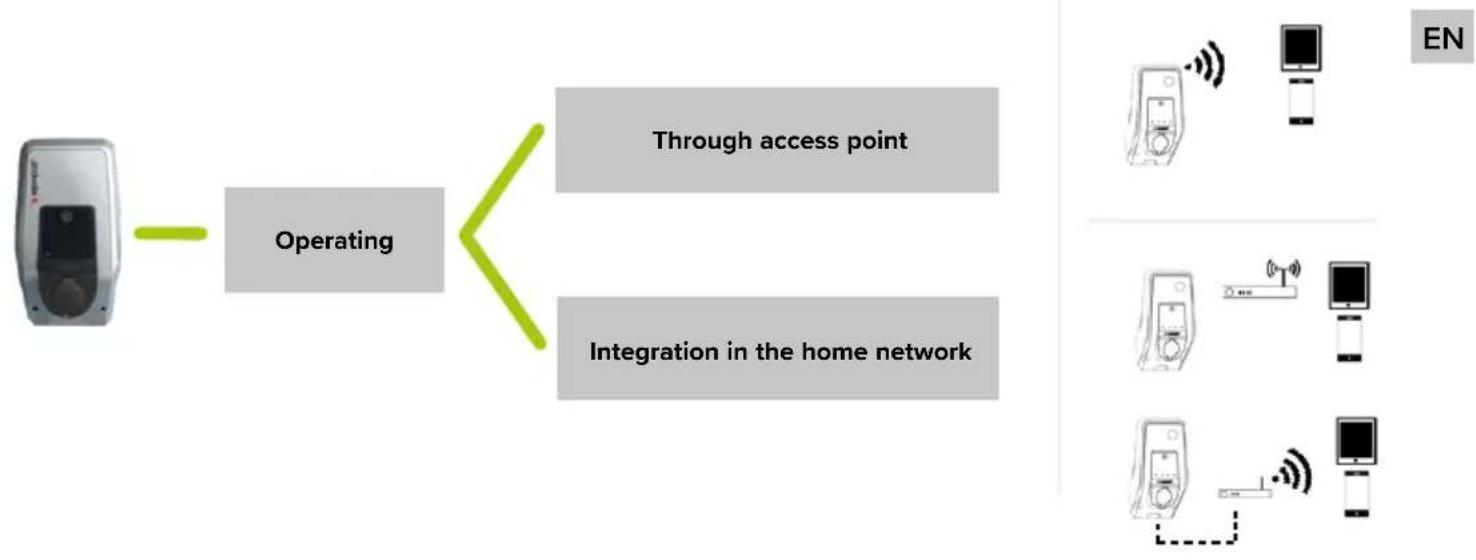
flowchart
graph LR
    A["Device"] --> B["Operating"]
    B --> C["Through access point"]
    B --> D["Integration in the home network"]
    E["Mobile Phone"] --> F["Mobile Phone"]
    G["Mobile Phone"] --> H["Mobile Phone"]
    I["Mobile Phone"] --> J["Mobile Phone"]
    K["Mobile Phone"] --> L["Mobile Phone"]
    M["Mobile Phone"] --> N["Mobile Phone"]
    O["Mobile Phone"] --> P["Mobile Phone"]
    Q["Mobile Phone"] --> R["Mobile Phone"]
    S["Mobile Phone"] --> T["Mobile Phone"]
    U["Mobile Phone"] --> V["Mobile Phone"]
    W["Mobile Phone"] --> X["Mobile Phone"]
    Y["Mobile Phone"] --> Z["Mobile Phone"]
    AA["Mobile Phone"] --> AB["Mobile Phone"]
    AC["Mobile Phone"] --> AD["Mobile Phone"]
    AE["Mobile Phone"] --> AF["Mobile Phone"]
    AG["Mobile Phone"] --> AH["Mobile Phone"]
    AI["Mobile Phone"] --> AJ["Mobile Phone"]
    AK["Mobile Phone"] --> AL["Mobile Phone"]
    AM["Mobile Phone"] --> AN["Mobile Phone"]
    AO["Mobile Phone"] --> AP["Mobile Phone"]
    AQ["Mobile Phone"] --> AR["Mobile Phone"]
    AS["Mobile Phone"] --> AT["Mobile Phone"]
    AU["Mobile Phone"] --> AV["Mobile Phone"]
    AW["Mobile Phone"] --> AX["Mobile Phone"]
    AY["EN"] --> AZ["Smartphone"]

For some tasks it is necessary to enter a PIN. These can be found on the set-up data sheet. After entering an incorrect PIN ten times, PIN input will be blocked for five minutes.
Through access point

The access point is always active if the device has not been integrated with WLAN in a home network or if no WLAN network is available.
▶ Activate WLAN on the terminal.
▶ Search for available WLAN networks.
▶ Select the network of the desired device. The name consists of the product name and the MAC address of the device (e.g. AMTRON_7C70BCxxx).
▶ Enter WLAN WPA2 key and connect to the network.
Integration in the home network
If the device and the terminal are integrated in the home network, no further configuration is necessary.
Î "6.3.2 Integrating into the home network"
6.7.2 Connection to the device
Automatic connection
▶ Open MENNEKES Charge APP.
- Tap "Search for Wallbox" to find the devices on your network.
▶ If the desired device has been found, select it using the serial number (SNR) (setup data sheet).
▶ Enter PIN1 (APP PIN) of the device and change the name if necessary.
▶ Confirm the entry with "Save".
Manual connection
In rare cases, the device will not be detected automatically. You can then connect the device manually.
▶ Touch "Set up manually".
▶ Enter the IP address and the respective PIN1 (APP PIN) of the device and change the name if necessary.
■ IP address as access point: 172.31.0.1
■ IP address for integration in the home network: depending on configuration
→“6.3.2 Integrating into the home network”
▶ Confirm the entry with "Save".
7. Maintenance
NGER
Electric shock hazard when devices are damaged
Use of a damaged device may result in electric shock.
▶ Do not use the device if it is damaged.
▶ Mark the damaged device to ensure that no one continues using it.
▶ Eliminate damage immediately.
▶ Stop the device if necessary,
Recommended maintenance intervals
Testing intervals of charging infrastructure for electric vehicles based on DGUV (German Social Accident Insurance) regulation 3.
| Component Maintenance work Person | ||
| responsible | ||
| Daily / At every charging | ||
| Device Visual inspection for defects | User / Owner | |
| Control of operational readiness | Owner | |
| Every 6 months | ||
| Residual current device | Function check Operator / electrician | |
| Charging cable | Repeat the measurements and tests according to VDE 0701/702 | Electrician |
| Once a year | ||
| Device Repeat the measurements and tests according to VDE 0105-100 | Electrician | |
▶ Document maintenance sufficiently.
▶ If necessary, request maintenance protocol from MENNEKES support.
→ "1.1 Service"

A maintenance contract ensures a regular check.
8. Troubleshooting
To correct the fault, observe the following sequence:
- Read the error code in the MENNEKES Charge APP.
- Remove the device from the mains for three minutes.
- Check the following aspects:
■ The device is properly connected and configured.
■ There is a power supply and a network connection.
■ The software is up to date.
■ All clamping points are fixed.
■ The pipes are in a proper condition.
-
Fix the problem using the error codes.
-
If necessary, contact your responsible service partner.
-
Acknowledge the fault, if necessary, with the multi-function button or stop button or disconnect the device from the mains for three minutes and restart it.
Operating manual AMTRON Xtra (E/R), Premium (E/R/W): "5.5 Multi-function button"
Operating manual AMTRON Xtra (E/R), Premium (E/R/W): "5.6 Stop button"
8.1 Fault code
Error codes are output in the service interface and in the MENNEKES Charge APP for a detailed error diagnosis.
Calling up in the service interface
▶ Navigate to "Production Settings".
√ "HCC3 Error Code" you can find the error code.
Calling up in the MENNEKES Charge APP
▶ Navigate to "Configure Wallbox" > "Wallbox Information".
The error code can be found in "Current error code".
| Error code | Meaning Trigger (examples) Remedy | ||
| 00 | No error | ||
| 10 | Installation Fault | Phase sequence relay faulty (e.g. wrong rotary field, missing phase) | ▶ Check the power supply.→“6.2 Monitoring power supply” |
| RCD or MCB has tripped | ▶ Switch on RCD or MCB.Operating manual AMTRON Xtra (E/R), Premium (E/R/W): “5.5 Multi-function button” | ||
| 11 | Controller fault | Device does not respond | ▶ Acknowledge the fault. |
| 12 | Misconfiguration | Charging not possible | ▶ Check settings in the service interface.▶ If the LED info field is permanently lit: Acknowledge the fault. |
| 13 | Overtemperature | Internal temperature sensor has triggered (at >60°C) | ▶ Allow the device to cool down.▶ Check location.→“5.1 Choice of location”▶ Acknowledge the fault. |
| 14 Mirror contact error | Contactor sticks or not tightened | ▶ Check contactor and replace if necessary. ▶ Acknowledge the fault. | |
| Mirror contact defective | ▶ Check mirror contact and replace if necessary. ▶ Acknowledge the fault. | ||
| 15 | Invalid device time | Invalid or no system time | →“6.6 Time synchronisation” |
| 16 | Home Manager connection error | No connection to the Energy Manager | ▶ Check network and Energy Manager settings in the service interface. ▶ Check the LAN / WLAN connection. |
| 30 Device startup | Device does not start or is in the faulty state after startup | ▶ Disconnect the device from the mains for three minutes and restart it. ▶ Acknowledge the fault. | |
| 31 | Internal test not passed | Device does not start | ▶ Disconnect the device from the mains for three minutes and restart it. ▶ Acknowledge the fault. |
| 32 HMI not connected | LED information field is dark and charge not possible | ▶ Check HMI cable connection and reestablish if necessary ▶ Acknowledge the fault. | |
| 50 | Badly plugged cable | Charging not possible | ▶ Disconnect charging cable and plug in again. |
| 51 | Wrong cable | Charging not possible | ▶ Check charging cable and replace if necessary. |
| 52 | Communication with the vehicle interrupted | Charging not possible | ▶ Disconnect the device from the mains for three minutes and restart it. ▶ If the LED info field is permanently lit: Acknowledge the fault. ▶ Check charging cable and replace if necessary. |
| 100 (only with operating mode “SCU”) | ACU communication error | Device does not receive data from the ACU | ▶ Check the configuration of the ACU. ▶ Check RS-485 bus. ▶ Disconnect the device from the mains for three minutes and restart it. |
| 101 (only with operating mode “SCU”) | Not polled by ACU | No connection with RS-485 bus | ▶ Reinitialize the RS-485 bus. As of HCC 3 software version 1.08, the RS-485 bus is initialized automatically after a certain time and the fault is eliminated. |
| 102 (only with operating mode “SCU”) | Maintenance | Maintenance is carried out in the service interface of the ACU | Once the maintenance is completed, the error code will no longer be displayed. |
| 103 (only with operating mode “SCU”) | Disabled | The charging point has been deactivated in the service interface of the ACU | ▶ Navigate to “Main page” > “Setup” > “SCU-Setup” in the service interface of the ACU. ▶ Deactivate “SCU Disabled”. □ Installation manual MENNEKES ACU / SCU |
| 255 Unknown error | |||
8.2 Spare Parts
If replacement or accessory parts are necessary for troubleshooting, these must first be checked to ensure the same design.
▶ Use only spare parts and accessories that are manufactured and / or approved by MENNEKES.
8.3 Unlocking the charging plug
If the unlocking function fails, the charging plug may be mechanically locked in place in the socket panel by the actuator. The charging plug cannot be removed and must be unlocked manually.
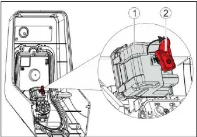
Fig.: 20. Unlock the charging plug
▶ Open the device.
→ "5.4 Opening the device"
▶ Attach the red lever (2) to the square shaft of the actuator (1). The red lever is attached with a cable tie close to the actuator.
▶ Turn the red lever on the actuator by 90 ° clockwise.
▶ Pull off the charging plug.
▶ Remove the red lever and attach it close to the actuator with a cable tie.
▶ Close the device
→ "5.9 Closing the device"
9. Taking out of service and dismantling
Disconnect the cables
▶ Open the device.
→ "5.4 Opening the device"
▶ Disconnect supply, data, and control lines
▶ Route the lines through the membrane screw connection from the enclosure.
Dismantling the device
▶ Remove plugs and screws.
▶ Remove the device from the wall.
▶ Close the device
→ "5.9 Closing the device"
10. Storage
Proper storage can positively affect and maintain the operability of the device.
▶ Clean the device before storing.
▶ Store the device in its original packaging or by using suitable packaging in a clean and dry place.
▶ Observe permissible storage conditions.
Permissible storage conditions
| Storage temperature -25°C... + 40 °C | |
| Average temperature over 24 hours | < 35 °C |
| Relative humidity max. 95 % | (non-condensing) |
11. Disposal
Discard the device and packaging according to regulations at the end of its service life. Observe the national regulations for disposal and environmental protection applicable in the country of use.
Old devices and batteries must not be disposed of with household waste.
▶ Dispose of packaging material in designated collection containers.
▶ Dispose of old devices and batteries via your dealer.
12. Accessory
Accessories such as protective roofs or charging cables can be found on our homepage under “Accessories”. https://www.chargeupyourday.com/

13. Glossary
| Term Explanation | |
| ACU Accounting | Control UnitUnit for communication with the SCUs / HCC 3s of the charging stations and for connection to back-end systems.An ACU is installed in the eMobility-Gateway and Smart charging stations. |
| Backend system | Infrastructure for controlling charging stations and managing personal access data. |
| CP Control Pilot | Cable in the plug and socket device for communication between vehicle and device. |
| eMobility-Gateway | MENNEKES eMobility-Gateway for intelligent networking of charging systems and for connection to back-end systems. |
| Fault-current circuit breaker | Residual current circuit breakerType A = sensitive to pulse currentType B = sensitive to all types of current |
| HCC 3 Unit for control of the charging process and communication with the vehicle (in mode 3 charging) | |
| Miniature circuit breaker (MCB) | Circuit breaker |
| Mode 3 (IEC 61851) | Charging mode for vehicles with communication interface on charging couplers type 2. |
| PP Proximity Pilot or Plug PresentContact for determining the current carrying capacity of the charging cable and activating the immobiliser. | |
| RFID Authorization option via RFID card to devices. | |
| RS-485 bus Interface standard for digital data transmission. In this case: Connection between ACU and up to 16 SCUs. | |
| SCU Socket Control UnitUnit used to control each charging spot and communicate with the vehicle. | |
| Type 2 (IEC 62196-2) | Single and three phase charging couplers with identical plug geometry for charging powers from 3.7 to 44 kW AC. |
| UID User IdentifierUser ID on a computer. | |
| Whitelist Internal database for managing user data (e.g. RFID cards). | |
Inhoudsopgave
6.4.2 Menu "Installation Settings" 22
6.4.3 Menu "User Settings" 23
6.4.4 Menu "Whitelist" 25
6.4.5 Menu "System" 27
6.5 Apparaat controleren.... 27
6.7 MENNEKES Charge App....28
6.7.1 Netwerkverbinding met MENNEKES Charge App....29
natural_image
Two identical devices with blue cables and a black central component, each mounted on a flat surface (no visible text or symbols)Afb.: 9. Montageafstanden [mm]
De groene led knippert.
NL
Eén fase:
natural_image
Illustration of a desktop computer setup with a speaker and a monitor, both emitting sound waves (no text or symbols)| Use Static IP Address | ☑ |
| Static IP Address | 192.168.178.222 |
| Static Netmask | 255.255.255.0 |
| Static Gateway Address | 192.168.178.1 |
6.4.2 Menu "Installation Settings"
■ Ethernet IP Address
■ Ethernet Subnet Mask
■ Ethernet Gateway IP Address
■ Source of Ethernet IP Address
■ Ethernet MAC Address
■ Active WLAN Mode
■ Status Details
■ Broadcasting SSID
■ WLAN Channel
■ WLAN MAC Address
■ Connected Clients
■ WLAN IP Address
■ WLAN Subnet Mask
6.4.4 Menu "Whitelist"

▶ PIN3 (whitelist PIN) invoeren.
Procedure "Firmware Update"
6.7 MENNEKES Charge App

Afb.: 19. Video "MENNEKES Charge App" (Engels)
Voorwaarden:
Afb.: 20. Laadstekker noodontgrendelen
▶ Apparaat openen.
→ "5.4 Apparaat openen"
▶ Apparaat openen.
→ "5.4 Apparaat openen"
https://www.chargeupyourday.com/

5. Installation....10
6.7 MENNEKES Charge APP....28
Fig.: 7. HCC 3 (exemple)
natural_image
Two identical white devices with blue cables and connectors, each labeled with dimensions (300, 300, 300) and a small 'MONSTER' logo on the top.Fig.: 12. Bornes de connexion
Fig.: 15. Raccordement du bus RS-485
natural_image
Simple line drawing of a desktop computer with monitor, tower, and mouse (no text or symbols)| Use Static IP Address | ☑ |
| Static IP Address | 192.168.178.222 |
| Static Netmask | 255.255.255.0 |
| Static Gateway Address | 192.168.178.1 |
Submit Changes
■ Ethernet IP Address
■ Ethernet Subnet Mask
■ Ethernet Gateway IP Address
■ Source of Ethernet IP Address
■ Ethernet MAC Address
■ Active WLAN Mode
■ Status Details
■ Broadcasting SSID
■ WLAN Channel
■ WLAN MAC Address
■ Connected Clients
■ WLAN IP Address
■ WLAN Subnet Mask
6.7 MENNEKES Charge APP

https://www.chargeupyourday.com/

13. Glossaire
6.4.2 Menu "Installation Settings" 22
6.4.3 Menu "User Settings" 23
6.4.4 Menu "Whitelist" 25
6.4.5 Menu "System" 27
https://www.chargeupyourday.com/
www.chargeupyourday.de

1.2 Avvertenze
Fig.: 1. Fornitura
Fig.: 4. Vista posteriore (esempio)
Fig.: 7. HCC 3 (esempio)
natural_image
Two identical devices with blue and black cables, each labeled with a dimension (300, 300300) and an 'MONSTER' logo on top, placed on a plain surface (no text or symbols on devices themselves)Fig.: 12. Morsetti
Fig.: 15. Collegamento bus RS-485
natural_image
Illustration of a remote control device emitting signal waves next to a desktop computer (no text or symbols)| Use Static IP Address | ☑ |
| Static IP Address | 192.168.178.222 |
| Static Netmask | 255.255.255.0 |
| Static Gateway Address | 192.168.178.1 |
6.4.2 Menu "Installation Settings"
■ Ethernet IP Address
■ Ethernet Subnet Mask
■ Ethernet Gateway IP Address
■ Source of Ethernet IP Address
■ Ethernet MAC Address
■ Active WLAN Mode
■ Status Details
■ Broadcasting SSID
■ WLAN Channel
■ WLAN MAC Address
■ Connected Clients
■ WLAN IP Address
■ WLAN Subnet Mask
6.4.4 Menu "Whitelist"

Fig.: 19. Video "MENNEKES Charge APP" (in inglese)
https://www.chargeupyourday.com/

13. Glossario
6. Igangsetting....17
6.4.2 Meny "Installation Settings" 22
6.4.3 Meny "User Settings" 23
6.4.4 Meny "Whitelist" 25
6.4.5 Meny "System" 27
6.5 Kontroller apparatet.... 27
6.6 Tidssynkronisering....28
6.6.1 Tidssynkronisering med MENNEKES Charge App....28
6.6.2 Tidssynkronisering i servicegrensesnittet...... 28
6.7 MENNEKES Charge App....28
8. Feilretting....31
8.1 Feilkoder....31
8.2 Reservedeler 33
https://www.chargeupyourday.com/faqs/

1.2 Advarsler
Advarsel om personskader

Fig.: 4. Sett bakfra (eksempel)
- Husunderdel
- Festeskruer for husoverdel
- Luftutløp
- Utsparing for tilførselsledning / kabelkanal
- Festehull
- Kabelinnföringer
Fig.: 7. HCC 3 (eksempel)
- Plugglist tariffomkobling
- Status LEDs
- Nettverkstilkobling (RJ45)
- Plugglist spenningsforsyning 12 V DC
- Plugglist RS-485-bus
- Plugglist ladestikkontakt
- Plugglist S0-måler
- Plugglist frontpanel
- Plugglist lavspenningssignal 230 V AC
Fig.: 8. Åpne apparatet
natural_image
Two identical white devices with blue cables and connectors, each labeled with a dimension (300, 300300) and an orange 'MONSTER' logo on the top.Fig.: 9. Monteringsavstander [mm]
Fig.: 14. Koble til tariffomkoblingssignal
▶ Avisoler styreledningen.
Koble fasen på klemme A og nøytralleder på klemme B på pluggforbindelsen (2).
Klemmer Beskrivelse
A Fase tariffomkoblingssignal 230 V AC
B Nøytralleder tariffomkoblingssignal 230 V AC
Koble pluggforbindelsen til tilsvarende pluggliste (2) på HCC 3 (1).
▶ Tilkobling til eksternt apparat i henhold til produsentens anvisninger.

Hvis tariffomkoblingssignalet skal kobles til en ekstern spenningskilde, må det sørges for en henvisning i samsvar med nasjonale bestemmelser (f.eks. et klistremerke).
Aktivering av tariffomkoblingssignalet foretas i servicegrensesnittet.
Fig.: 15. Tilkobling RS-485 bus
natural_image
Simple line drawing of a device with wireless signal and a separate electronic device (no text or symbols)| Use Static IP Address | ☑ |
| Static IP Address | 192.168.178.222 |
| Static Netmask | 255.255.255.0 |
| Static Gateway Address | 192.168.178.1 |
Fig.: 18. Innstillinger i servicegrensesnittet ved tildelingen av en statisk IP adresse (tilkobling med LAN). Ruteren er en FRITZ!Box.
Forutsetninger for nettleser:
6.4.2 Meny "Installation Settings"
I menyen "Installation Settings" kan innstillinger gjøres for igangsettingen.
■ Ethernet IP Address
■ Ethernet Subnet Mask
■ Ethernet Gateway IP Address
■ Source of Ethernet IP Address
■ Ethernet MAC Address
Nettverkstilkobling via Access Point
■ Active WLAN Mode
■ Status Details
■ Broadcasting SSID
■ WLAN Channel
■ WLAN MAC Address
■ Connected Clients
■ WLAN IP Address
■ WLAN Subnet Mask
6.4.4 Meny "Whitelist"

Menyen "Whitelist" vises kun hvis en RFID-kortleser er tilgjengelig på apparatet (på versjone-ne Premium (E/R/W)).
▶ Tast inn PIN3 (Whitelist PIN).
NO
6.7 MENNEKES Charge App

Fig.: 19. Video "MENNEKES Charge APP" (engelsk)
Forutsetninger:
Fig.: 20. Nødløsne ladepluggen
- Åpne apparatet.
→ "5.4 Åpne apparatet"
▶ Sett den røde spaken (2) inn på firkantaksen på aktuatoren (1). Den røde spaken er festet med en kabelbinder i nærheten av aktuatoren.
Drei den røde spaken på aktuatoren 90° med urviseren.
▶ Trekk ut ladepluggen.
Fjern den røde spaken og fest spaken i nærheten av aktuatoren med en kabelbinder.
▶ Lukk apparatet.
→ "5.9 Lukk apparatet"
https://www.chargeupyourday.com/

13. Ordliste
5. Installation....10
6.7 MENNEKES Charge APP....28
6.7.1 Nätverksanslutning med MENNEKES Charge APP....29
6.7.2 Anslutning till enheten....30
7. Underhåll....30
8. Felsökning....31
8.1 Felkoder....31
8.2 Reservdelar....33
www.chargeupyourday.com

natural_image
Two identical white devices with blue cables and connectors, each labeled with a dimension (300, 300300) and an orange 'MONSTER' logo on the top.→ "6.4.2 Menyn "Installation Settings"
natural_image
Simple line drawing of a device with a speaker emitting sound waves and a desktop computer (no text or symbols)IP-adress: 172.31.0.1
| Use Static IP Address | ☑ |
| Static IP Address | 192.168.178.222 |
| Static Netmask | 255.255.255.0 |
| Static Gateway Address | 192.168.178.1 |
Submit Changes
■ Ethernet IP Address
■ Ethernet Subnet Mask
■ Ethernet Gateway IP Address
■ Source of Ethernet IP Address
■ Ethernet MAC Address
■ Active WLAN Mode
■ Status Details
■ Broadcasting SSID
■ WLAN Channel
■ WLAN MAC Address
■ Connected Clients
■ WLAN IP Address
■ WLAN Subnet Mask
6.4.4 Menyn "Whitelist"
▶ Ange PIN 3 (Whitelist-PIN).
6.7 MENNEKES Charge APP

https://www.chargeupyourday.com/

13. Ordlista
6.4.2 Menú "Installation Settings" 22
6.4.3 Menú "User Settings" 23
6.4.4 Menú "Whitelist" 25
6.4.5 Menú "System" 27
6.7 MENNEKES Charge APP....28
https://www.chargeupyourday.com/faqs/

1.2 Advertencias
Fig: 7. HCC 3 (ejemplo)
natural_image
Two identical white devices with blue cables and connectors, each labeled with dimensions (300, 300, 300) and a small 'MONSTER' logo on the top.Fig: 9. Distancias de montaje [mm]
Fig: 12. Bornes de conexión
Fig: 13. Conectar el cable de red
Fig: 15. Conexión del bus RS-485
"Monitoring Relay Wired to 1 Phase Only".
→ "6.4.2 Menú "Installation Settings"
Ajuste Descripción
Fig: 16. Interruptor de configuración
Ajuste Descripción
natural_image
Illustration of a remote control device emitting signal waves next to a desktop computer (no text or symbols)| Use Static IP Address | ☑ |
| Static IP Address | 192.168.178.222 |
| Static Netmask | 255.255.255.0 |
| Static Gateway Address | 192.168.178.1 |
Submit Changes
6.4.2 Menú "Installation Settings"
6.4.4 Menú "Whitelist"

6.7 MENNEKES Charge APP

https://www.chargeupyourday.com/

13. Glosario
5. Installation....10
6.4.2 Menu "Installation Settings" 22
6.4.3 Menu "User Settings" 23
6.4.4 Menu "Whitelist" 25
6.4.5 Menu "System" 27
6.7 MENNEKES Charge APP....28
Fif.: 4. Set bagfra (eksempel)
- Kabinettets underdel
- Monteringsskruer til kabinettets overdel
- Luftåbning
- Forstanset hul til kabel / kabelkanal
- Monteringshuller
- Kabelindføringer
Frontpanel, indvendig
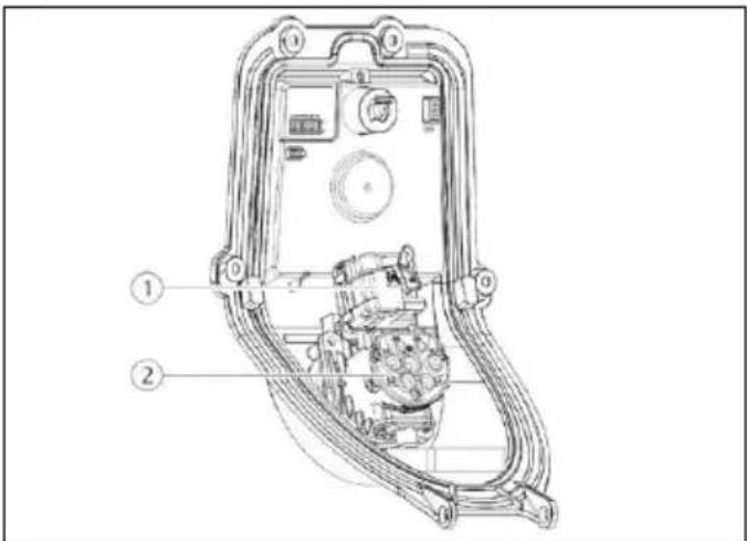
Fif.: 6. Kabinettets underdel, indvendig (eksempel)
Fif.: 7. HCC 3 (eksempel)
Fif.: 8. Åbne apparat
natural_image
Two identical white devices with blue cables and connectors, each labeled with dimensions (300, 300, 300) and a small 'MONSTER' logo on the top.Fif.: 14. Tilslutte tarifskiftesignal
Fif.: 15. Tilslutning RS485-bus
→ "6.4.2 Menu "Installation Settings"
Indstilling Beskrivelse
1 Enfaset drift
3 Trefaset drift
5.8 Konfigurationsknap
natural_image
Simple line drawing of a device with wireless signal and a separate electronic device (no text or symbols)| Use Static IP Address | ☑ |
| Static IP Address | 192.168.178.222 |
| Static Netmask | 255.255.255.0 |
| Static Gateway Address | 192.168.178.1 |
Submit Changes
6.4.2 Menu "Installation Settings"
■ Ethernet IP Address
■ Ethernet Subnet Mask
■ Ethernet Gateway IP Address
■ Source of Ethernet IP Address
■ Ethernet MAC Address
■ Active WLAN Mode
■ Status Details
■ Broadcasting SSID
■ WLAN Channel
■ WLAN MAC Address
■ Connected Clients
■ WLAN IP Address
■ WLAN Subnet Mask
6.4.4 Menu "Whitelist"

▶ Indtast PIN3 (Whitelist PIN).
▶ Vælg i menuen "Whitelist" undermenuen "Add Entry".
6.7 MENNEKES Charge APP

Fif.: 19. Video
"MENNEKES Charge
APP" (engelsk)
https://www.chargeupyourday.com/

- Glossar
6.7 MENNEKES Charge APP 28
natural_image
Two identical devices with blue and black cables, each labeled with a dimension (300, 300300), no visible text or symbols on the devices themselves.- ábra: Fali rögzítés
natural_image
Illustration of a desktop computer with wireless signal and a laptop (no text or symbols)| Use Static IP Address | ☑ |
| Static IP Address | 192.168.178.222 |
| Static Netmask | 255.255.255.0 |
| Static Gateway Address | 192.168.178.1 |
Submit Changes
■ Ethernet IP Address
■ Ethernet Subnet Mask
■ Ethernet Gateway IP Address
■ Source of Ethernet IP Address
■ Ethernet MAC Address
■ Active WLAN Mode
■ Status Details
■ Broadcasting SSID
■ WLAN Channel
■ WLAN MAC Address
■ Connected Clients
■ WLAN IP Address
■ WLAN Subnet Mask
6.4.4 „Whitelist“ menü

6.7 MENNEKES Charge APP

6.7 MENNEKES Charge APP 28
natural_image
Two identical devices with blue and black cables, each mounted on a white surface, with dimension annotations (300, 300, 300) shown at the base.natural_image
Simple line drawing of a remote control device emitting sound waves next to a desktop computer (no text or symbols)| Use Static IP Address | ☑ |
| Static IP Address | 192.168.178.222 |
| Static Netmask | 255.255.255.0 |
| Static Gateway Address | 192.168.178.1 |
Submit Changes
■ Ethernet IP Address
■ Ethernet Subnet Mask
■ Ethernet Gateway IP Address
■ Source of Ethernet IP Address
■ Ethernet MAC Address
■ Active WLAN Mode
■ Status Details
■ Broadcasting SSID
■ WLAN Channel
■ WLAN MAC Address
■ Connected Clients
■ WLAN IP Address
■ WLAN Subnet Mask
6.7 MENNEKES Charge APP

https://www.chargeupyourday.com/

13. Глоссарий
6.4.2 Valikko "Installation Settings" 22
6.4.3 Valikko "User Settings" 23
6.4.4 Valikko "Whitelist"......25
6.4.5 Valikko "System" 27
6.7 MENNEKES Charge APP....28
www.chargeupyourday.com

https://www.chargeupyourday.com/faqs/

1.2 Vaaraohjeet
natural_image
Two identical devices with blue cables and a black central component, each mounted on a white surface (no visible text or symbols)natural_image
Illustration of a desktop computer with wireless signal and a laptop (no text or symbols)| Use Static IP Address | ☑ |
| Static IP Address | 192.168.178.222 |
| Static Netmask | 255.255.255.0 |
| Static Gateway Address | 192.168.178.1 |
Submit Changes
6.4.2 Valikko "Installation Settings"
6.4.3 Valikko "User Settings"
■ Ethernet IP Address
■ Ethernet Subnet Mask
■ Ethernet Gateway IP Address
■ Source of Ethernet IP Address
■ Ethernet MAC Address
■ Active WLAN Mode
■ Status Details
■ Broadcasting SSID
■ WLAN Channel
■ WLAN MAC Address
■ Connected Clients
■ WLAN IP Address
■ WLAN Subnet Mask
6.4.4 Valikko "Whitelist"

6.7 MENNEKES Charge APP

Kuvio: 19. Video
"MENNEKES Charge
APP" (englanti)