AMTRON Premium 11 - Car charger Mennekes - Free user manual and instructions
Find the device manual for free AMTRON Premium 11 Mennekes in PDF.

User questions about AMTRON Premium 11 Mennekes
0 question about this device. Answer the ones you know or ask your own.
Ask a new question about this device
Download the instructions for your Car charger in PDF format for free! Find your manual AMTRON Premium 11 - Mennekes and take your electronic device back in hand. On this page are published all the documents necessary for the use of your device. AMTRON Premium 11 by Mennekes.
USER MANUAL AMTRON Premium 11 Mennekes
natural_image
Black-and-white photo of a Mendeke EV charging station mounted on a wall, showing its cable and charging port (no visible text or symbols)Charging station for Electric Vehicles
Operation manual for the User
4.7 MENNEKES Charge APP 20
natural_image
Three-panel image showing a blue electric vehicle charging plug, its internal components, and its wiring (no visible text or symbols)Abb. 1
text_image
Technical diagram of a mobile phone casing with numbered components for identificationnatural_image
Line drawing of a device with a probe inserted into a socket (no text or symbols)4.7 MENNEKES Charge APP
Production Settings Installation Settings Customer Settings Whitelist Operation Software Update
Abb. 14: Hauptmenü
text_image
Time Info Local Timestamp: | ? | 1427191248 Currently Summer: | ? | Timezone Offset (Minutes): | ? | 60 SubmitAbb. 15: Menü „Customer Settings / Time Info“
text_image
Production Settings QS Info HMI HW Version: AA-01330 HMI SW Version: 1.006 HMI Type: L HMI IO Status: ? 0110 HMI Temperature Internal [°C]: 28 HMI Temperature External [°C]: 0 HMI Error Code: 0000 RFID Version: TWN4/B1.03/CB1.49/APP1.00 YLAN Version: 03.41021 HCC3 HW Version: ? 30545-AA-00136 HCC3 SW Version: ? 1.05 HCC3 IO-State: ? 110000 HCC3 CP/PP-State: ? C11 HCC3 Error Code: ? 0 AMTRON Operation Mode: ? Remote AMTRON State : ? Paused AMTRON RS485 Address : ? AMTRON Connector Type: Cable Type 2 AMTRON No. of Phases: 3 AMTRON Rated Current [A]: ? 32 AMTRON Serial Number: ? 20200010 AMTRON Order Number: ? 345202 AMTRON External Temperature Sensor Installed: AMTRON Local Fuses Installed: AMTRON Production Settings Write Enabled false HCC3 Ethernet MAC Address: 7c70bc801024 HCC3 Total Energy [kWh]: 4text_image
Installation Settings Installation info AMTRON Installation Current [A]: 16 Home Manager Installed: External Tariff Switch Installed: SubmitAbb. 17: Menü „Installation Settings“
text_image
Customer Settings Customer Info AMTRON Customer Current Limitation [A] | ? 32 AMTRON Wallbox Name : ? AMTRON Enable RFID Authorization : ? ✓ Power Fail Continue: ✓ Autostart Charging : ? ✓ Enable Stop Button: ✓ Color Schema: IDLE - blue, CHARGE - green, WAIT - white, ERROR - red ✓ Enable RFID Beep: ✓ Enable WLAN Communication: ✓ AMTRON Operation Mode: Switch to operation mode "Remote" Submit WLAN Info STA SSID: ? FRTZ/Box STA Connected? true STA Security Mode: ? No security STA Security Key : ? AP Security Mode: WPA2 AES PSK mode AP Channel: 6 AP Country Code: ? DE Submit Time Info Local Timestamp : ? 1412607779 Currently Summer : ? ✓ Timezone Offset [Minutes] : ? 60 Submit SW Reset ResetAbb. 18: Menü „Customer Settings“
text_image
Insert or Update Whitelist Entry Name: ? UID: ? Pin: ? Master: ? Submit Delete whitelist entry UID: ? Pin: ? Deletetext_image
Software Update Init Software Update InitContent subject to changes without notice.
This document is protected by copyright. It helps to ensure the device is used safely and efficiently by the user. The contents may not be duplicated or reproduced, in whole or in part, without the prior consent of the copyright holder.
Document symbols
Listing
√ Check / Result
Tip
→ Reference to another page in this document
Reference to another document
Table of Contents
1 General....2
1.1 Structure of the Operating Manual 2
2 Safety 2
2.1 General Safety Information 2
2.2 Safety Information 3
2.3 Intended Use.... 3
2.4 Qualification of Personnel 3
2.5 Warranty....3
2.6 Returning Devices 3
3 Product Description....4
3.1 General information....4
3.2 Optional equipment 4
3.3 Identification Plate 5
3.4 Delivery Contents....6
3.5 Assembly....6
3.5.1 Exterior view....6
3.6 Components 7
3.6.1 Front panel 7
3.6.2 HC controller 7
4 Operation....9
4.1 General information on operation....9
4.2 LED Info bar 10
4.3 Multi-function button 11
4.3.1 Terminating an on-going charging process 11
4.3.2 Re-activating the residual current circuit breaker and circuit breaker .... 11
4.3.3 Testing the integrated residual current circuit breaker (RCCB)....11
4.4 Description of operating modes 12
4.4.1 Settings in operating mode "Energy Manager" 17
4.5 Charging the vehicle 17
4.5.1 Charging without authorisation 17
4.5.2 Authorisation with RFID 18
4.5.3 Authorisation with Charge APP....18
4.5.4 Mode 3 charging 18
4.5.5 Terminating the charging process ..... 19
4.5.6 Power failure during charging process ..... 19
4.6 Managing RFID cards....19
4.6.1 Adding RFID cards with the master RFID card 19
4.6.2 Adding and deleting RFID cards with the Charge APP....19
4.6.3 Adding and deleting RFID cards with the service interface 19
4.6.4 Notes on RFID cards taught as masters.....20
4.7 MENNEKES Charge APP 20
4.7.1 Requirements....20
4.7.2 Automatic connection of the Charge APP . 20
4.7.3 Manual connection of the Charge APP .....21
4.8 Configuration of the charging station 22
4.8.1 Access over WLAN 22
4.8.2 Access over LAN 22
4.8.3 Time synchronisation 23
4.8.4 Menu description....24
5 Maintenance....28
5.1 Maintenance plan 28
6 Troubleshooting....29
6.1 Troubleshooting by the operator 29
7 Disassembly, Storage and Disposal ....31
7.1 Disassembly....31
7.2 Storage 31
7.2.1 Ambient conditions....31
7.3 Disposal 31
8 Appendix....32
8.1 Accesories 32
8.2 Glossary 32
8.3 Index....33
1 General
This manual is an important aid for ensuring the fault-free and safe operation of the device.
The specifications in this manual apply only to the device stated in the product description.
Read this manual before setting up the device.
Using this manual will help you to:
■ avoid any risks for the user;
■ become acquainted with the device;
■ achieve optimum functioning;
■ promptly detect and rectify faults;
■ avoid any malfunctions due to improper installation;
■ cut down on repair costs and reduce the number of downtimes;
■ improve the reliability and increase the service life of the system;
■ avoid causing harm to the environment.
These instructions are an important part of the product and must be retained for future reference.
MENNEKES Elektrotechnik GmbH & Co. KG accepts no liability for any damage resulting from non-observance of the information in this manual.
1.1 Structure of the Operating Manual
General Information
This chapter contains general information on the Operation manual.
Safety
This chapter contains details on the presentation of safety information, provisions for liability and warranty and information on intended use.
Product Description
This chapter contains basic information on the device and its construction.
Operation
This chapter contains information on operating the device.
Maintenance
This chapter provides details on the required maintenance work and instructions on exchanging components when necessary.
Disassembly, Storage and Disposal
This chapter provides information on correctly disassembling storing and disposing of the device.
Appendix
This chapter contains a list of the available accessories, the glossary and the index of the this document.
2 Safety
2.1 General Safety Information
The device has been designed using state-of-the-art technology and is safe to operate.
Nevertheless, there may be residual risks associated with the device under the following circumstances:
■ The device is not used as intended.
■ Non-compliance with the safety information given in this manual.
■ The device is damaged.
■ The device is not maintained properly.
■ The device is modified or converted improperly.
■ The maintenance work specified in this manual is not carried out in due time.
Danger
Risk of death resulting from non-compliance with documentation!
Any person authorised to work on the system must have read and understood this manual, in particular the "Safety" chapter.
The electrical installation, initial operation and servicing of the device may only be performed by qualified electricians who have been authorised by the operator.
2.2 Safety Information
To recognise safety instructions in this manual at a glance, the following signal words and symbols are used:

Danger
This symbol in conjunction with the signal word "Danger" indicates an imminent danger. Failure to follow the safety instructions will result in death or serious injury.

Warning
This symbol in conjunction with the signal word "Warning" indicates a potentially hazardous situation. Failure to follow the safety instructions may result in death or serious injury.

Caution
This symbol in conjunction with the signal word "Caution" indicates a potentially hazardous situation. Failure to follow the safety instruction may result in light or minor injuries.
Caution
This note indicates a potentially harmful situation. Failure to follow the safety instructions may result in damage to, or destruction of the product and / or other components.
2.3 Intended Use
The device may be used for the purpose described in 3 "Product Description" on page 4 and in conjunction with the supplied and approved components.
Any use exceeding the aforementioned shall be deemed unintended. MENNEKES assumes no liability for damage resulting from non-intended use. The risk is borne solely by the user / operator.
Intended use also includes:
■ compliance with all the information in this manual;
■ carrying out of servicing tasks according to schedule.
The device may present hazards, if it is not used as intended.
2.4 Qualification of Personnel
The electrical installation, setup and maintenance of the device may only be performed by qualified electricians, who have received authorisation from the system operator to perform such tasks. Such persons must have read and understood the operating manual and must comply with the information therein.
Requirements of qualified electricians:
■ Knowledge of general and special safety and accident prevention guidelines.
■ Knowledge of relevant electrical guidelines (e.g. DIN VDE 0100 section 600 DIN VDE 0100722), as well as valid national regulations.
■ The ability to recognize risks and avoid possible dangers.
2.5 Warranty
In the event of complaints regarding the product, please contact your responsible service partner immediately and provide the following information:
■ type designation / serial number;
■ date of manufacture;
■ reason for complaint;
■ duration of use;
■ ambient conditions (temperature, humidity).
2.6 Returning Devices
In case you return the device to MENNEKES for repair, please use the original packaging or a suitable, safe transport container.
3 Product Description
3.1 General information
The MENNEKES AMTRON ^® Wallbox is a charging station for use in private and semi-public areas, such as private land, company car parks and depots.
The charging station is used exclusively for charging electrically powered vehicles.
■ Mode 3 charging according to IEC 61851-1:2010.
■ Plugs and sockets according to IEC 62196.
The charging station is operated as a stand-alone solution or with connection to a higher-level back-end system.
The charging station is intended solely for fixed installation.
Features:
■ Status information through LED info bar.
■ Integration into the home network over WLAN / LAN.
■ RS485 interface for wired networking with a MENNEKES ACU or MENNEKES E-Mobility Control Panel (SCU mode).
■ Charge APP for controlling the charging process and displaying statistical data.
■ MENNEKES HC controller, communication and control unit.
■ Multi-function button (termination of charging process, RCCB test, re-activation of RCCBs and CBs).
■ Unlocking function in case of power failure for charging with charging plug type 2 (mode 3) (only for devices with charging plug type 2).
■ Enclosure made of AMELAN.
■ Integrated cable storage.
■ Wired ready for connection.
3.2 Optional equipment
Depending on the version of the charging station, the following optional features are available:
Connector systems
natural_image
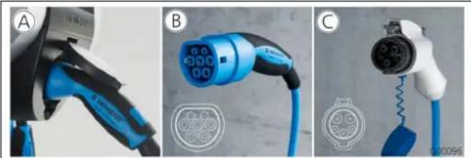
Three-panel image showing a blue electric vehicle charging plug, its internal components, and a connected plug with a black cable (no visible text or symbols)Fig. 1
Depending on the version, the charging station is equipped one of the following connector systems:
Ⓐ Charging socket type 2 for use with separate charging cable.
(B) Permanently connected charging cable with charging connector type 2.
© Permanently connected charging cable with charging connector type 1.

| Xtra^1) | Xtra E^2) | Xtra R^2) | Trend E^2) | Premium^1) | Premium R^2) | |
| LED info bar | √ | √ | √ | √ | √ | √ |
| Multi-function button | ||||||
| ■ Stop function (adjustable parameters, deactivated by default) | √ √ | √ √ √ √ | ||||
| ■ Reset function | √ √ | √ √ √ √ | ||||
| ■ Testing the residual current circuit breaker | √ | — | √ | — | √ √ | |
| ■ Re-activating the residual current circuit breaker | √ | — | √ | — | √ √ | |
| Residual current circuit breaker (RCCB) | √ | — | √ | — | √ | √ |
| Circuit breaker (CB) | √ | — | — | — | √ | — |
| Calibrated digital energy meter | √ √ | √ | — | √ | √ | |
| Charge APP for authorising and visualising charging processes | √ | √ | √ | √ | √ | √ |
| Statistics function over Charge APP | √ √ | √ | — | √ | √ | |
| Charged amount of energy displayed on Charge APP | √ √ | √ | — | √ √ | ||
| RFID system for authorising charging processes | — — — | √ √ √ | ||||
1) Version for Germany
2) EU version
3.3 Identification Plate
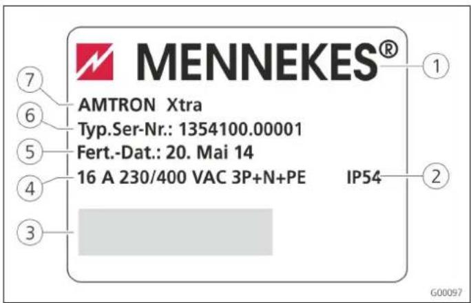
④ Supply network connection
⑤ Date of manufacture
⑥ Part number / serial number
⑦ Type
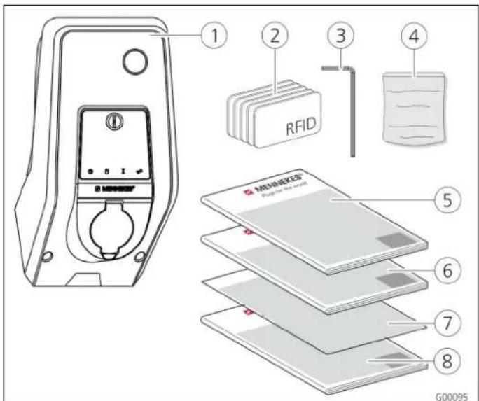
3.4 Delivery Contents
text_image
1 2 3 4 RFID MENKES® Papier to be used 5 6 7 8 G00095Fig. 3: Delivery contents
① Charging station
② RFID cards (2x master, 3x user) ^1)
③ Allen key
④ Bag with installation hardware (screws, dowels, plugs)
1) Only for versions Trend, Premium.
⑤ Operation manual
⑥ Installation manual
⑦ Set-up data sheet
⑧ Quick guide
! CAUTION
Negative impact on the device function
Without set-up data sheet, access to certain functions and the configuration of the device is not possible.
Keep the set-up data sheet in a safe place for later use.
3.5 Assembly
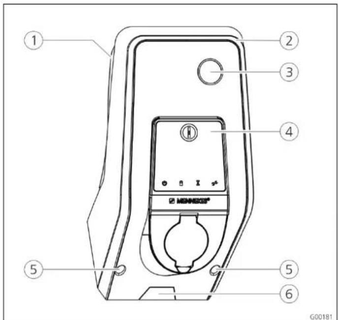
3.5.1 Exterior view
text_image
① ② ③ ④ ⑤ ⑤ ⑥ G00181Fig. 4: Front view (example)
① Rear enclosure part
② Front enclosure part
③ Window for counter
④ Front panel
⑤ Fastening screws for front enclosure part
⑥ Predetermined breaking point for supply line / cable duct from below
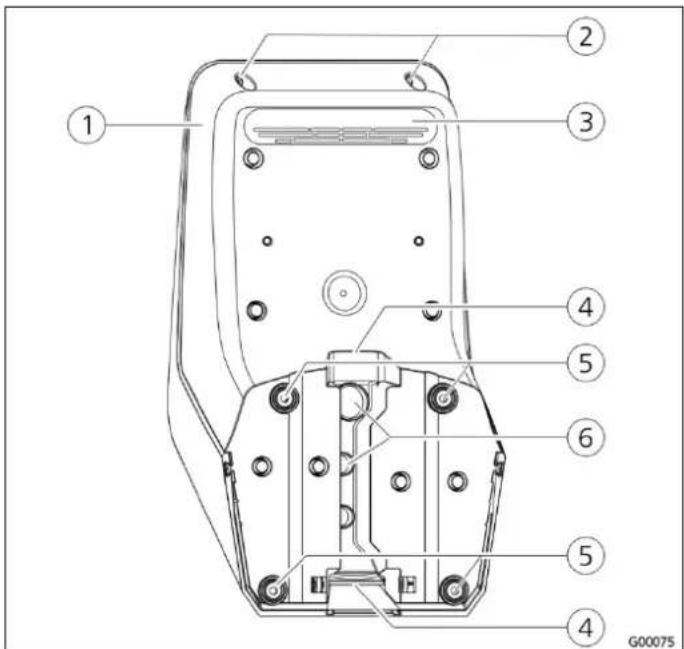
text_image
Technical diagram of a mobile phone casing with numbered components for identificationFig. 5: Rear view (example)
① Rear enclosure part ④ Opening for cable duct
② Fastening screws for front ⑤ Fastening holes
enclosure part
6
Cable glands
③ Air outlet
The enclosure of the charging station has three parts and consists of rear enclosure part, front enclosure part and the front panel.
The front panel has to be folded down to access the internal components. The design of the front panel depends on the version of the charging station.
→ See Chapter 3.6.1 "Front panel" on page 7.
3.6 Components
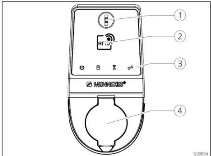
3.6.1 Front panel
text_image
1 2 RFID 3 MENNEKES® 4 G00094Fig. 6: Front panel (example)
① Multi-function button
② RFID card reader ^1)
③ LED info bar
④ Charging socket type 2 with hinged lid
The control and display elements as well as the charging socket of the charging station are located on the front panel. The design of the front panel depends on the version of the charging station.
3.6.2 HC controller
The HC controller controls the charging process in a fully automatically and performs the following functions:
■ Communication with Charge APP over WLAN.
■ Communication with service interface over WLAN / LAN.
■ Analysis of the data from a connected meter.
■ Analysis of the monitoring system's data
■ Detecting the current-carrying capacity of the charging cable with resistance coding. Unsuitable charging cables are rejected.
■ It checks that the requirements for proper charging have been met.
■ Querying an external signal (tariff switching).
■ It uses the CP contact to communicate with the vehicle. Using a PWM signal, the charging current upper limit is transmitted to the vehicle. The ground conductor connection is checked at the same time.
■ Controlling the locking of the charging plug in the charging socket (for devices with charging socket Type 2).
■ Controlling the charging contactor.
The HC controller provides five operating modes that can be changed even during operation depending on the configuration. The operating mode is selected over the service interface or the MENNEKES Charge APP.
The availability of the operating modes and functions depends on the version of the charging station and the configuration of the charging station during the setting-up process. When switching to operating mode "SCU", the HC controller must be restarted.
Operating mode "Manual (Remote)"
In this operating mode, the charging process is controlled by the Charge APP.
→ See table "Functional description of manual operating mode (remote)" on page 12.
Operating mode "Time-Controlled (internal)"
In this operating mode, the charging process is controlled by the integrated tariff-switching timer. This allows adapting the available charging current to various main / off-peak tariffs. For example, during an off-peak period the charging station can charge with higher charging power than during more expensive main tariff periods.
The valid tariff periods supplied by the electricity provider are entered in the Charge APP and the charging station adapts the charging current according to the periods entered.
Updating the tariff-switching timer and changing of daylight saving / standard time happen in connection with the charge APP.
→ See table "Functional description for operating mode time-controlled (internal)" on page 13.
Operating mode "External Tariff Signal"
In this operating mode, the charging process is controlled over an external contact (such as a ripple control receiver). In addition, the available charging current can be adapted to various main / off-peak tariffs as in operating mode "Time-Controlled"
→ See table "Functional description of operating mode External Tariff Signal" on page 14.
Operating mode "Energy Manager"
In this operating mode, the charging process is controlled over the SUNNY HOME MANAGER (www.SMA-Solar.com). The charging station is connected to the SUNNY HOME MANAGER over LAN / WLAN. Both devices must be on the same network.
The SUNNY HOME MANAGER then controls the charging power depending on the energy generated by the photovoltaic system and user preferences.
→ See table "Functional description of operating mode Energy Manager" on page 15.
Operating mode "SCU"
In this operating mode, the charging process is controlled by a higher-level back-end system (such as MENNEKES E-Mobility Control Panel).
The charging station is connected to a MENNEKES ACU over RS485.
In operating mode SCU, control over Charge APP or switching to other operating modes is not possible.
→ See table "Functional description of operating mode SCU" on page 16.
4 Operation
4.1 General information on operation
Operating the charging station depends on the selected operating mode.
→ See Chapter 4.4 "Description of operating modes" on page 12.
All information on the status of your charging station is displaced at a glance on your smart phone or tablet.
Operating with Charge APP
The operation with Charge APP is largely self-explanatory.
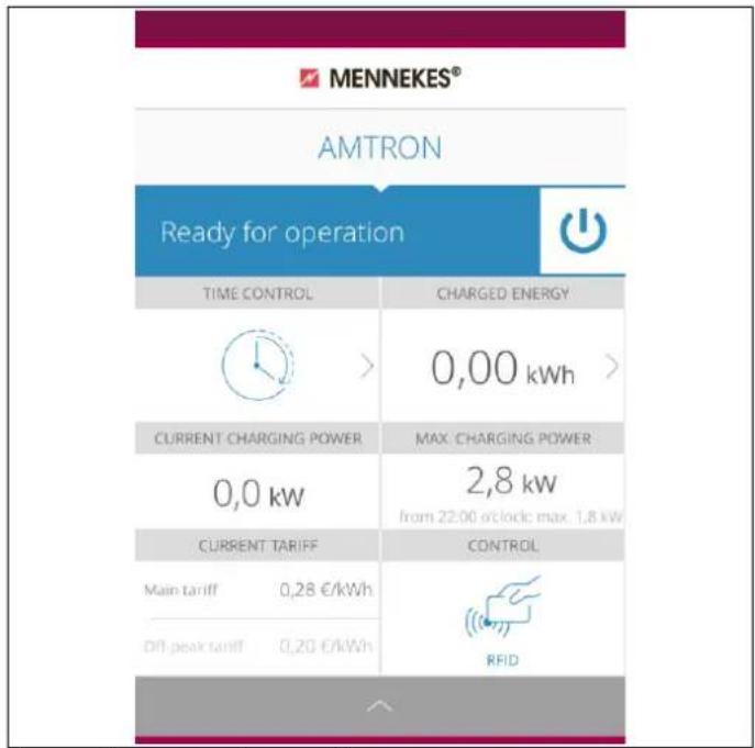
text_image
MENNEKES® AMTRON Ready for operation TIME CONTROL CHARGED ENERGY 0,00 kWh > CURRENT CHARGING POWER MAX. CHARGING POWER 0,0 kw 2,8 kw from 22:00 o'clock max. 1,8 kw CURRENT TARIFF CONTROL Main tariff 0,28 €/kWh Off-peak tariff 0,20 €/kWh RFIDFig. 7: Charge APP (example)
The Charge APP informs you during the charging process on the amount of energy that has already been charged.
You can start, pause and terminate the charging process manually with the APP and choose from three different charging modes to optimise energy costs.
4.2 LED Info bar
The LED info bar displays the operating status of the charging station. The colour scheme (green / blue) for "Operational / Charging" depends on the setting over the service interface during the setting-up process. The Charge APP uses the same symbols for displaying the operating status.
| LED info bar | Charge APP | Description |
 lit blue permanently lit blue permanently |  lit blue permanently lit blue permanently | OperationalThe charging station is operational; no vehicle is connected to the charging station. |
 pulsating green pulsating green |  pulsating green pulsating green | Ready to charge: vehicle pausesAll requirements for charging an electric vehicle are met.A charging process is not taking place.The charging process is paused due to a vehicle feedback or was terminated by the vehicle. |
 lit green permanently lit green permanently |  lit green permanently lit green permanently | Ready to chargeAll requirements for charging an electric vehicle are met.The charging process is paused due to a missing activation signal or a charging current configuration of 0 A. |
 lit green permanently lit green permanently |  animated green animated green | Charging process activeAll requirements for charging an electric vehicle are met. Charging in progress. |
 flashes green flashes green |  animated green animated green | Overtemperature warningThe charging station reduces the charging current to prevent overheating and deactivation. |
 flashes blue flashes blue |  steady white steady white | Wait periodConnection with vehicle is pending or has been established or charging pauses due to specification by the Charge APP.A subsequent action is required, such as connecting or disconnecting the charging cable, starting the charging process by RFID card or Charge APP. |
 lit red permanently lit red permanently |  lit red permanently lit red permanently | FaultA fault prevents the vehicle from charging.→ See Chapter 6 "Troubleshooting" on page 29. |
 Flashes red Flashes red |
4.3 Multi-function button
text_image
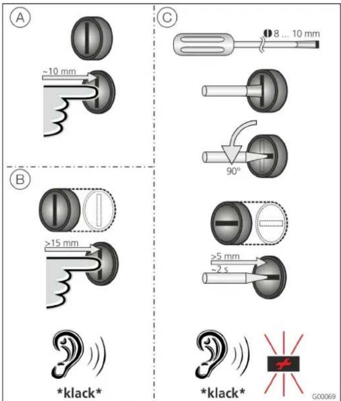
A ~10 mm B >15 mm *klack* C 8 ... 10 mm 90° >5 mm ~2 s *klack* G00069Fig. 8: Multi-function button
The multi-function button has several functions:
(A) Terminating an on-going charging process (only for charging stations without authorisation) and acknowledging of errors.
(B) Re-activating the residual current circuit breaker (RCCB) and / or circuit breaker (CB) in case of failure.
© Triggering the test-function of the residual current circuit breaker (RCCB).
4.3.1 Terminating an on-going charging process
Press the multi-function button to terminate a charging process. The charging process will be terminated and the charging plug of charging stations with charging socket type 2 will be unlocked.
The stop function with the multi-function button must be enabled in the service interface during the setting-up process of the charging station. See Chapter 4.8 "Configuration of the charging station" on page 22.
4.3.2 Re-activating the residual current circuit breaker and circuit breaker
The multi-function button can be used to re-activate the residual current circuit breaker (RCCB) and circuit breaker (CB) inside the charging station mechanically from the outside without opening the enclosure.
- Press the multi-function button until you feel resistance.
- Now press the multi-function button firmly up to the end position.
Residual current circuit breaker (RCCB) and circuit breaker (CB) are re-activated and charging station is operational again.
4.3.3 Testing the integrated residual current circuit breaker (RCCB)
The multi-function button can be used to trigger the test-function of the residual current circuit breaker (RCCB) inside the charging station from the outside without opening the enclosure.
- Insert a flat screwdriver with a blade width of 8 to 10 mm in the slot of the multi-function button.
- Turn the multi-function button by 90° anti-clockwise.
- Press the multi-function button briefly (about 2 seconds).
The residual current circuit breaker (RCCB) is triggered and the fault display on the LED info bar flashes red. - Re-activate the residual current circuit breaker (RCCB) (see Chapter 4.3.2 "Re-activating the residual current circuit breaker and circuit breaker" on page 11).
4.4 Description of operating modes
| Functional description of manual operating mode (remote) | |
| Start of charging process | Without RFID card:■ Automatically after connection to the vehicle■ Manually with Charge APP |
| With RFID card: | ■ Authentication with valid RFID card■ Manually by selecting a valid RFID card in Charge APP |
| Controlling the charging process | By using the Charge APP■ Changing the charging current for the on-going charging process■ Interrupting the charging process (pause)■ Continuing the charging process■ Terminating the charging process (stop) |
| By using the multi-function button:■ Terminating the charging process (stop)The stop function with the multi-function button must be enabled during the setting-up process. | |
| With RFID card: | ■ Terminating the charging process (stop, with the same card used for starting the charging process) |
| ☀ In operating mode "manual", all functions of other operating modes are suspended. The charging power, for example, will not be controlled over time, the external tariff-switching signal or the "SUNNY HOME MANAGER". | |
| Changing the operating mode | The Charge APP or service interface allows changing the operating mode configured during the setting-up process. The change of operating mode will apply for the on-going and subsequent charging processes. |
| Response to power failure | The response to power failure is configured during the setting-up process.■ The charging process is aborted (default with authorisation enabled).■ The charging process is continued (default for automatic start). |
| Functional description for operating mode time-controlled (internal) | |
| Start of charging process | Without RFID card:■ Automatically after connection to the vehicle |
| With RFID card: | ■ Authentication with valid RFID card■ Manually by selecting a valid RFID card in Charge APP |
| Controlling the charging process | By using the internal timer:■ Adapting the charging current depending on the active period (main tariff / off-peak tariff). |
| By using the Charge APP | ■ Terminating the charging process (stop) |
| By using the multi-function button:■ Terminating the charging process (stop)The stop function with the multi-function button must be enabled during the setting-up process. | |
| With RFID card: | ■ Terminating the charging process (stop, with the same card used for starting the charging process) |
| ☆ In operating mode "Time-Controlled (internal)" , all functions in operating modes "External Tariff Signal" and "Energy Manager" are suspended. The charging power, for example, will not be controlled over the external tariff-switching signal or the "SUNNY HOME MANAGER". | |
| Changing the operating mode | By using the Charge APP during a charging process:■ Change to operating mode "Manual (Remote)".The change of operating mode will apply to the on-going charging process. The following charging process is carried out according to the mode selected in the user settings of the Charge APP. |
| In the user settings of the Charge APP: | ■ Changing to all operating modes configured during the setting-up process.The change of operating mode will apply for the on-going and subsequent charging processes. |
| By using the service interface: | ■ Changing to all operating modes configured during the setting-up process.The change of operating mode will apply for the on-going and subsequent charging processes. |
| Response to power failure | The response to power failure is configured during the setting-up process.■ The charging process is aborted (default with RFID card reader).■ The charging process is continued (default without RFID card reader). |
| Functional description of operating mode External Tariff Signal | |
| Start of charging process | Without RFID card:■ Automatically after connection to the vehicle |
| With RFID card: | ■ Authentication with valid RFID card■ Manually by selecting a valid RFID card in Charge APP. |
| Controlling the charging process | By using the external tariff-switching signal:■ Adapting the charging current depending on the active period (main tariff / off-peak tariff). |
| By using the Charge APP: | ■ Terminating the charging process (stop) |
| By using the multi-function button:■ Terminating the charging process (stop)The stop function with the multi-function button must be enabled during the setting-up process. | |
| With RFID card: | ■ Terminating the charging process (stop, with the same card used for starting the charging process) |
| ☆ In operating mode "External Tariff Signal", all functions in operating modes "Time-Controlled" and "Energy Manager" are suspended. The charging power, for example, will not be controlled over the internal timer or the "SUNNY HOME MANAGER". | |
| Changing the operating mode | By using the Charge APP during a charging process:■ Change to operating mode "Manual (Remote)".The change of operating mode will apply to the on-going charging process. The following charging process is carried out according to the mode selected in the user settings of the Charge APP. |
| In the user settings of the Charge APP: | ■ Changing to all operating modes configured during the setting-up process.The change of operating mode will apply for the on-going and subsequent charging processes. |
| By using the service interface: | ■ Changing to all operating modes configured during the setting-up process.The change of operating mode will apply for the on-going and subsequent charging processes. |
| Response to power failure | The response to power failure is configured during the setting-up process.■ The charging process is aborted (default with RFID card reader).■ The charging process is continued (default without RFID card reader). |
| Functional description of operating mode Energy Manager | |
| Start of charging process | Without RFID card:■ Automatically after connection to the vehicle |
| With RFID card: | ■ Authentication with valid RFID card■ Manually by selecting a valid RFID card in Charge APP. |
| Controlling the charging process | By using the "SUNNY HOME MANAGER":■ The "SUNNY HOME MANAGER" specifies the charging current according to the parameters set in the Charge APP.→ See Chapter 4.4.1 "Settings in operating mode "Energy Manager"" on page 17. |
| By using the Charge APP: | ■ Terminating the charging process (stop)■ Changing the remaining amount of charging energy.■ Changing the remaining charging time.■ Changing the distribution of solar energy (enable / disable excess charging). |
| By using the multi-function button:■ Terminating the charging process (stop)The stop function with the multi-function button must be enabled during the setting-up process. | |
| With RFID card: | ■ Terminating the charging process (stop, with the same card used for starting the charging process) |
| ☆ In operating mode "Energy Manager", all functions in operating modes "Time-Controlled (internal)" and "External Tariff Signal" are suspended. The charging power, for example, will not be controlled over the internal timer or external tariff-switching signal. | |
| Changing the operating mode | By using the Charge APP during a charging process:■ Change to operating mode "Manual (Remote)".The change of operating mode will apply to the on-going charging process. The following charging process is carried out according to the mode selected in the user settings of the Charge APP. |
| In the user settings of the Charge APP: | ■ Changing to all operating modes configured during the setting-up process.The change of operating mode will apply for the on-going and subsequent charging processes. |
| By using the service interface: | ■ Changing to all operating modes configured during the setting-up process.The change of operating mode will apply for the on-going and subsequent charging processes. |
| Response to power failure | The response to power failure is configured during the setting-up process.■ The charging process is aborted (default with RFID card reader).■ The charging process is continued (default without RFID card reader). |
| Functional description of operating mode SCU | |
| Start of charging process | With RFID card:■ Authentication with valid RFID card |
| Controlling the charging process | By using the higher-level back-end system:■ Control takes place completely over the higher-level back-end system. |
| By using the multi-function button:■ Terminating the charging process (stop)The stop function with the multi-function button must be enabled during the setting-up process. | |
| With RFID card: | ■ Terminating the charging process (stop, with the same card used for starting the charging process) |
| ☀ In operating mode "SCU", all functions of other operating modes are suspended. Using the Charge APP is not possible. | |
| Changing the operating mode | By using the service interface:■ Changing to all operating modes configured during the setting-up process. |
| Response to power failure | The response to power failure is configured during the setting-up process.■ The charging process is aborted (default with and without RFID card reader).■ The charging process is continued. |
4.4.1 Settings in operating mode "Energy Manager"
The operating mode "Energy Manager" must be enabled during the setting-up process by the installer to become available.
If operating mode "Energy Manager" is selected, you must make the following settings over the Charge APP or in the portal of the "SUNNY HOME MANAGER" (SHM).
Charge APP - parameter "battery capacity"
Enter the maximum capacity of the battery of your electric vehicle. The entered value is transmitted to the SHM as the upper limit for the energy requirements for a charging process.
Charge APP - parameter "energy demand"
Enter the minimum amount of energy for a charging process. The value is transmitted to the SHM together with the maximum charging time. The SHM calculates the amount of energy that must be supplied within the charging time. This ensures that the specified amount of energy is charged. The remaining amount of energy required is obtained from public electricity network.
Charge APP - parameter "maximum charging time"
Enter the maximum time for charging the amount of energy to the vehicle specified with the parameter "energy demand".
Charge APP - parameter "excess charging"
Select the option "excess charging" if you want to use only excess energy for charging your electric vehicle.
The parameters "maximum charging time" and "energy demand" are then ignored.
The amount of energy in the parameter "battery capacity" is sent to the SHM as optional energy. You need to set the conditions for the optional energy in the SHM portal.
If the "battery capacity" parameter is set to 0 kWh, charging in operating mode "Energy Manager" cannot take place.
Make sure that the ratio of the parameters "battery capacity" and "energy demand" is a meaningful value. The maximum charging power of the charging station must be considered as well.
4.4.1.1 Charging in operating mode "Energy Manager"
- Connect the charging cable to charging station and vehicle.
- Authorise when needed.
√ The charging station changes to the state "charging active" and the charging process starts with a charging capacity of 0 kW. From now on, the SUNNY HOME MANAGER controls the charging power.
In case of connection problems to the SUNNY HOME MANAGER, the charging current is limited to 6 A (emergency charging).
4.5 Charging the vehicle
Warning
Risk of injury due to incorrect handling!
Using an extension cable or second charging cable may result in electric shock or cable fire. Using extension cables is not permitted.
■ Never use more than one charging cable for connection the electric vehicle to the charging station.
■ Use only undamaged charging cables.
Depending on the configuration, charging is possible with or without authorisation.
4.5.1 Charging without authorisation
If the charging station was configured during the setting-up process that no authorisation is required, the charging process starts automatically after connecting the charging cable to the vehicle.
4.5.2 Authorisation with RFID
For RFID authorization, prior once-off registration of the user's RFID card at the charging station is required. The charging station can manage up to 100 RFID cards (2x master, 98x users) in an internal database (whitelist).
Two ways are possible for managing the RFID card:
■ Independent operation without Charge APP:
The operator of the charging station is authorised by his master RFID card to add new RFID cards to the internal database.
■ Managing RFID cards over the Charge APP:
In conjunction with Mennekes Charge APP, the internal database (whitelist) is particularly convenient for RFID authorisation. Names can be additionally assigned to RFID card numbers in the Charge APP and the database can be easily managed with a smart phone or tablet.
4.5.2.1 Authorisation with RFID card
■ Hold the RFID card against the RFID symbol on the front panel.
√ While the data are verified, the symbol "wait time" lights up on the LED info bar.
√ After successful authorisation, the charging station is set to the status "operational" and you can begin charging by connecting the charger cable.
If charging does not start within the release time of approximately 60 seconds, the authorisation is reset and the charging system changes to status "operational". A new authorisation is required.
4.5.3 Authorisation with Charge APP
You can also select an RFID card from the internal database (whitelist) for authorisation. You will need PIN 2 (whitelist PIN, see set-up data sheet).
The charging station then responds as if you have authorised directly at the charging station with a valid RFID card.
4.5.4 Mode 3 charging
natural_image
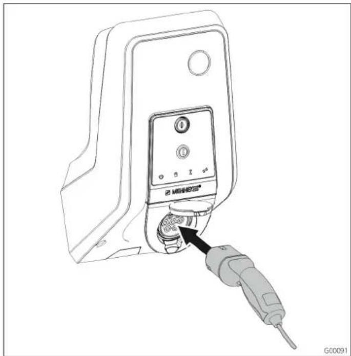
Line drawing of a device with a probe inserted into a socket (no text or symbols)Fig. 9: Connecting the charging cable (example)
Authorisation took place or authorization was not activated during the setting-up process.
Ensure that the vehicle and charging cable are suitable for mode 3 charging.
- Connect the charging cable to the vehicle.
- Insert the plug of the charging cable completely into the charging socket type 2 at the charging station (only for charging stations with integrated charging socket type 2).
The charging station performs now the following steps automatically:
■ Detecting the current-carrying capacity of the charging cable with resistance coding. Unsuitable charging cables are rejected.
■ It checks that the requirements for proper charging have been met.
It uses the CP contact to communicate with the vehicle. Using a PWM signal, the charging current upper limit is transmitted to the vehicle. The ground conductor connection is checked at the same time.
√ The charging system interlocks the charging plug mechanically (only for charging stations with integrated charging socket type 2). The vehicle signals to the charging system that it is ready for charging. The charging process starts.
√ The symbol "Charging in Progress" lights up on the LED info bar.
The maximum available charging current depends on the following points
■ Power rating of the charging station.
■ Features / version of the charging station.
■ Current-carrying capacity of the cable.
■ Configuration during setting-up process and setting of the charging current over the Charge APP.
■ Configuration of operating modes "Time-Controlled", "External Tariff Signal" and "Energy Manager".
4.5.5 Terminating the charging process
Caution
Damage to the charging cable.
Pulling the cable may cause cable breaks and other damages.
Remove the charging cable only by pulling the plug from the charging socket.
- Press the multi-function button on the charging station (see Chapter 4.3.1 "Terminating an on-going charging process" on page 11) or terminate the charging process at the vehicle.
- Remove the plug of the charging cable from the charging socket (only for charging stations with integrated charging socket type 2).
- Remove the charging cable from the vehicle.
4.5.6 Power failure during charging process
A power failure aborts the charging process.
The charging plug of charging stations with charging socket type 2 is unlocked and removed.
If the charging plug cannot be pulled out, an actuator has mechanically interlocked the charging plug.
→ See Chapter 6 "Troubleshooting" on page 29.
4.6 Managing RFID cards
For RFID authorization, prior once-off registration of the user's RFID card at the charging station is required.
The charging station can manage up to 100 RFID cards (2x master, 98x users) in an internal database (whitelist).
4.6.1 Adding RFID cards with the master RFID card
You can add RFID cards to the internal database (whitelist) with the master RFID card.
Adding a new RFID card:
- Hold the master RFID card against the RFID symbol to activate teach mode.
√ The symbol 📋 on the LED info bar flashes rapidly. - Hold the RFID card for teaching against the RFID symbol within 30 seconds.
√ The symbol 📋 on the LED info bar flashes briefly and then continues to flash rapidly. Teach mode is extended by an additional 30 seconds. - Hold another RFID card against the RFID symbol for teaching or hold the master RFID card against the RFID symbol to terminate teach mode.
√ The RFID card has been added to the internal database (whitelist).
If during teach mode for an RFID card the symbol lights up permanently, the internal database (whitelist) is full and no more cards can be added.
4.6.2 Adding and deleting RFID cards with the Charge APP
You can manage the database (whitelist) comfortably by using the Charge APP on a smart phone or tablet.
4.6.3 Adding and deleting RFID cards with the service interface
You can add RFID cards to or remove from the internal database (whitelist) with the service interface.
→ See "Menu "Whitelist Operation" " on page 27.
4.6.4 Notes on RFID cards taught as masters
The charging station comes with two RFID cards marked as AMTRON Master.
No charging processes can be authorised with cards marked as masters.
The charging station requires two RFID cards taught as masters.
If a card taught as master is deleted with the service interface or the Charge APP, the next unknown RFID card held against the RFID card reader will be taught as master.
4.7 MENNEKES Charge APP
4.7.1 Requirements
The following requirement must be met to connect the Charge APP to the charging station.
■ Installation of the Charge APP on a mobile device (smart phone, tablet). The MENNEKES Charge APP is available free of charge in Apple App Store, Google Play store and BlackBerry World.
■ Integration of the charging station in the home network over LAN / WLAN. The customer's WLAN must be available at the location of the charging station!
■ The charging station is turned on and operational.
■ The smart phone / tablet must have access to the home network (WLAN) or to the WLAN provided by the charging station.
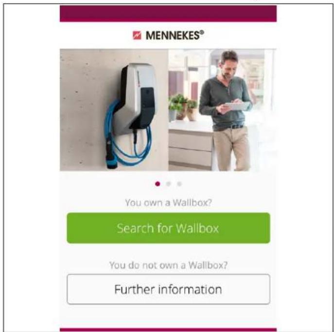
4.7.2 Automatic connection of the Charge APP
text_image
MENNEKES® You own a Wallbox? Search for Wallbox You do not own a Wallbox? Further informationFig. 10: Start menu
- Open Charge APP.
- Tap on "search for Wallbox" to search for charging stations available on your network.
- Select the desired charging station by the serial number (SNR, see set-up data sheet).
If a charging station was found, a menu for entering the name and PIN 1 of the charging station is displayed.
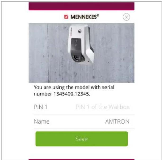
text_image
MENNEKES® You are using the model with serial number 1345400.12345. PIN 1 PIN 1 of the Wallbox Name AMTRON SaveFig. 11: Entering PIN and name
- Enter the PIN 1 associated with the displayed serial number (see set-up data sheet) of the charging station and change the suggested name as desired (maximum 22 characters).
- Confirm the entry with "Save".
The successful set-up is confirmed with a dialogue box. If another charging station has been detected, perform steps 3 and 4 again until all charging stations found have been set up.
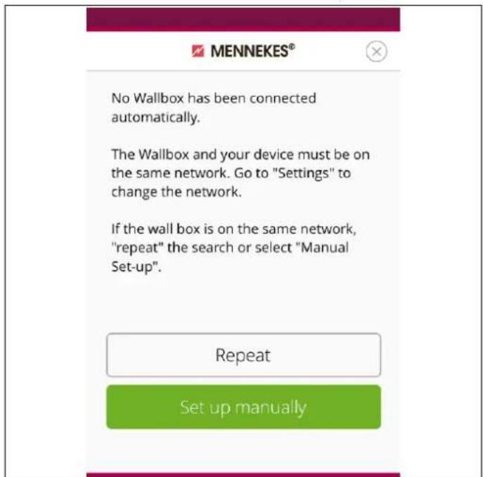
4.7.3 Manual connection of the Charge APP
text_image
MENNEKES® No Wallbox has been connected automatically. The Wallbox and your device must be on the same network. Go to "Settings" to change the network. If the wall box is on the same network, "repeat" the search or select "Manual Set-up". Repeat Set up manuallyFig. 12: Message "no Wallbox detected"
In rare cases, charging stations will not be detected automatically. You then have the option to repeat the search or set up the charging stations manually.
The IP address of the charging station must be known for manual set-up.
- Tap on "set up manually"

text_image
MENNEKES® Enter IP address and PIN 1 of the Wallbox. IP 192.168.0.10 PIN 1 •••••••• Name Default SaveFig. 13: Entering IP address, Pin and name
- Enter the IP address and the associated PIN 1 of the charging station and change the suggested name as desired.
- Confirm the entry with "Save".
√ The successful set-up is confirmed with a dialogue box.
4.8 Configuration of the charging station
Functions and operating modes are configured with the service interface in the Internet browser of the charging station. The service interface of the charging station is accessible over LAN or WLAN.
Requirements for Internet browsers:
■ JavaScript activated
■ Microsoft Internet Explorer 11 or higher
■ Mozilla Firefox version 30 or higher
■ Google Chrome version 35 or higher
■ Opera version 20 or higher
■ Current smart phone browsers (iOS, Android)
4.8.1 Access over WLAN
In access point mode, the service interface is accessible over http://172.31.0.1:25000.
In a home network, the charging station receives the IP address over the DHCP function of the customer's Internet router. You can retrieve the IP address with the web interface of the internet router or with an app such as the free of charge network scanner Fing.
The address looks as follows: http://AMTRONIP:25000 (e.g. http://192.168.0.20:25000).
Access is the same as for the direct connection.
4.8.2 Access over LAN
■ The charging station receives the IP address over the DHCP function of the customer's Internet router. You can retrieve the IP address over web interface of the Internet router.
■ If DHCP is not available, access is possible over LAN with IP address http://192.168.0.100:25000, network mask 255.255.255.0.
■ A direct cable connection without DHCP is possible.
4.8.2.1 Calling up the service interface
Follow these steps to access the service interface:
- Enter IP address and port number in the address bar of your Internet browser (http://AMTRONIP: 25000).
- Enter PIN 1 (APP PIN, see set-up data sheet) of the charging station.
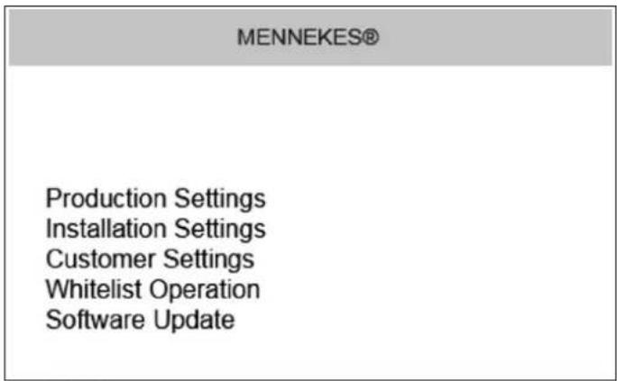
- The main menu of the service interface opens.
text_image
MENNEKES® Production Settings Installation Settings Customer Settings Whitelist Operation Software UpdateFig. 14: Main menu
- Select the required submenu.
For some parameters, tooltips with further information are available. Point your mouse over the "?" on the appropriate parameter. Clicking is not necessary.
4.8.3 Time synchronisation
During the initial setting-up process and after a power failure of more than 4 hours, a clock synchronisation is necessary.
Time synchronisation is possible with a smartphone / tablet over the charge APP or with a PC running the service interface in an Internet browser.
Time synchronisation with a smartphone / tablet
Time synchronisation with smart phone / tablet over the charge app takes place automatically as soon as a connection to the charging station has been established. There is no need for further action.
Time synchronisation with PC
Time synchronisation with a PC takes place with the service interface in an Internet browser
Carry out the following steps to synchronise time in the service interface.
- Open the service interface.
- Select the submenu "Customer Settings" in the service interface.
- The menu "Time Info" shows the settings required for the setting-up process.
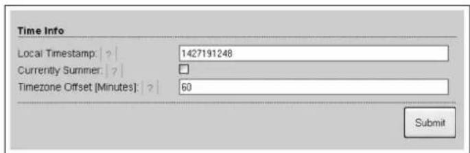
text_image
Time Info Local Timestamp: | ? | 1427191248 Currently Summer: | ? | Timezone Offset [Minutes]: | ? | 60 SubmitFig. 15: Menu "Customer Settings / Time Info"
-
The value "Local Timestamp" is required in format Unixtime.
-
You can convert the current date and time with a timestamp converter such as www.unixtime.de.
-
Enter the value obtained in the field "Local Timestamp".
-
Activate the input filed "Currently Summer" during daylight saving time.
-
Set the input filed "Timezone Offset" to the default value "60".
The "Timezone Offset" is the difference between the local time zone and the Coordinated Universal Time (UTC) in minutes.
Example of Germany and Central Europe The difference between the local time zone and UTC is 1 hour; therefore, set the parameter "Timezone Offset" to 60 minutes.
- Confirm the entry with "Submit".
The charging station is now ready for operation.
4.8.4 Menu description
Menu "Production Settings"

text_image
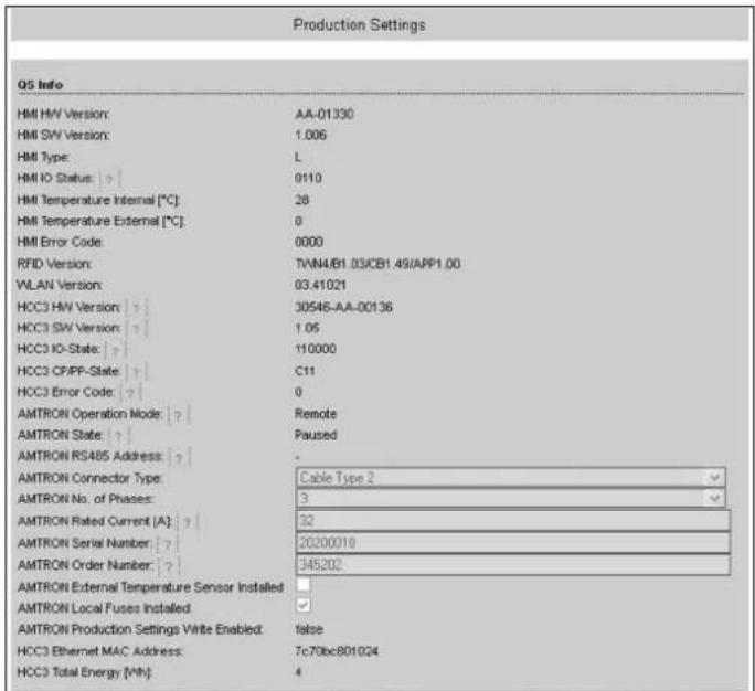
Production Settings QS Info HMI HIV Version: AA-01330 HMI SW Version: 1.006 HMI Type: L HMI IO Status: 0110 HMI Temperature Internal [℃] 28 HMI Temperature External [℃] 0 HMI Error Code: 0000 RFID Version: TWN4/B1.03/CB1.49/APP1.00 VLAN Version: 03.41021 HCC3 HIV Version: 30546-AA-00136 HCC3 SW Version: 1.05 HCC3 IO-State: 110000 HCC3 CP/PP-State: C11 HCC3 Error Code: 0 AMTRON Operation Mode: Remote AMTRON State: Paused AMTRON RS485 Address: - AMTRON Connector Type: Cable Type 2 AMTRON No. of Phases: 3 AMTRON Rated Current [A]: 32 AMTRON Serial Number: 20200010 AMTRON Order Number: 345202 AMTRON External Temperature Sensor Installed: AMTRON Local Fuses Installed: AMTRON Production Settings Write Enabled: false HCC3 Ethernet MAC Address: 7c70bc801024 HCC3 Total Energy [Wh]: 4Fig. 16: Menu "Production Settings"
The menu "Production Settings" displays factory settings and the hardware / software versions. You cannot make any settings here.
| Value Description | |
| HMI HW Version | Hardware version of the front panel |
| HMI SW Version | Software version of the front panel |
| HMI Type | Type of front panel |
| HMI IO Status | Status of the front panel's inputs and outputs |
| HMI Temperature | Internal and external front panel temperature |
| HMI Error Code | Error code of the front panel |
| RFID Version | Version of the RFID card reader |
| WLAN Version | Version of the WLAN module |
| Value Description | |
| HCC3 HW Version | Hardware version of the HC controller |
| HCC3 SW Version | Software version of the HC controller |
| HCC3 IO State Status of the HC controller's inputs and outputs | |
| HCC3 CP/PP State | Status of CP/PP signal contacts |
| HCC3 Error Code | Error code of the HC controller |
| AMTRON Operating Mode | Operating mode of the charging station→ See Chapter 4.4 on page 12 |
| AMTRON State Operating state of the charging station | |
| AMTRON Connector Type | Connector system of the charging station |
| AMTRON No. of Phases | Number of mains phases |
| AMTRON Rated Current | Maximum charging current |
| AMTRON Serial Number | Serial number of the charging station |
| AMTRON Order Number | Order number of the charging station |
| AMTRON External Temperature Sensor | ☐ No external temperature sensor available☑ External temperature sensor available |
| AMTRON Local Fuses Installed | ☐ No internal circuit breaker and residual current circuit breaker available☑ Internal circuit breaker and residual current circuit breaker available |
| AMTRON Production Settings Write Enabled | ■ true: production settings read-only■ false: production settings write enabled |
| HCC3 Ethernet MAC Address | MAC address of the HC controller's LAN interface |
| HCC3 Total Energy | Sum of the charged energy in Wh |
Menu "Installation Settings"

text_image
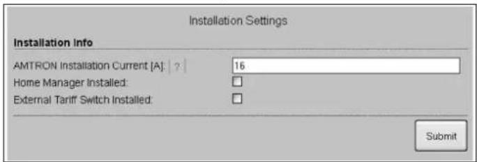
Installation Settings Installation info AMTRON Installation Current [A]: 16 Home Manager Installed: External Tariff Switch Installed: SubmitFig. 17: Menu "Installation Settings"
The menu "Installation Settings" shows the settings applied by the installer during the setting-up process. You cannot make any settings here.
| Value Description | |
| AMTRON Installation Current | Maximum charging current specified during setting-up process |
| AMTRON Home Manager Installed | ☐ No SMA SUNNY HOME MANAGER® available☑ SMA SUNNY HOME MANAGER® available→ See Chapter 4.4.1 on page 17 |
| AMTRON External Tariff Switch Installed | ☐ >No external tariff-switching signal available☑ External tariff-switching signal available |
Menu "Customer Settings"
text_image
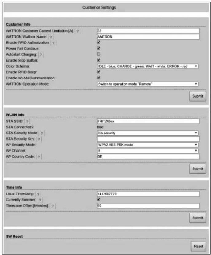
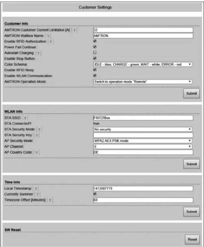
Customer Settings Customer Info AMTRON Customer Current Limitation [A] ? 32 AMTRON Wallbox Name ? AMTRON Enable RFID Authorization ? ✓ Power Fail Continue: ✓ Autostart Charging : ? ✓ Enable Stop Button: ✓ Color Schema: IDLE - blue; CHARGE - green; WAIT - white; ERROR - red Enable RFID Beep: ✓ Enable WLAN Communication: ✓ AMTRON Operation Mode: Switch to operation mode "Remote" Submit WLAN Info STA SSID: ? FRITZ/Box STA Connected? true STA Security Mode: ? No security STA Security Key : ? AP Security Mode: WPA2 AES PSK mode AP Channel: 6 AP Country Code: ? DE Submit Time Info Local Timestamp : ? 1412607779 Currently Summer : ✓ Timezone Offset [Minutes] : ? 60 Submit SW Reset ResetFig. 18: Menu "Customer Settings"
The menu "Customer Settings" can be used to make customer specific settings. Changes take effect by clicking on the button "Submit".
| Value | Description |
| AMTRONCustomerCurrentLimitation | Setting the limit of the maximum available charging current in A. |
| AMTRONWallboxName | Setting the device name. The device name is displayed in the Charge APP and the service interface. |
| Enable RFIDAuthorisation | Enable / disable RFID card reader.☑ RFID card reader enabled☐ RFID card reader disabled |
| Value Description | |
| Power Fail Continue | Enable / disable continue charging process after power failure☑ The charging process continues after a power failure☐ A power failure terminates the charging process |
| Autostart Charging | Enable / disable autostart of charging process☑ The charging process starts automatically when connected to a vehicle.☐ The charging process must be started manually when connected to a vehicle.⭐ This setting will be ignored with RFID card reader enabled. |
| Enable Stop Button | Enable / disable stop button.☑ Stop button enabled☐ Stop button disabled |
| Color Schema Setting the colour scheme of LED info bar | |
| Enable RFID Beep | Enable / disable audible feedback of the RFID card reader.☑ Audible feedback enabled☐ Audible feedback disabled |
| Enable WLAN Communication | Enable / disable WLAN module.☑ WLAN module enabled☐ WLAN module disabled |
| AMTRON Operation Mode | Selecting the operating mode of the charging station.→ See Chapter 4.4 on page 12. |
| Value Description | |
| STA SSID Name of the WLAN the charging station is connected to. | |
| STA Connected | Status of the WLAN connection.■ true: Charging station is connected to a WLAN■ false: No connection of the charging station to a WLAN |
| STA Security Mode | Selecting the WLAN encryption.Default setting: "Autodetect security mode" |
| STA Security Key | Entering the WLAN security key. |
| AP Security Mode | Selecting the WLAN encryption when charging station is operated in access point mode. |
| AP Channel Selecting the WLAN channel when charging station is operated in access point mode. | |
| AP Country Code | Selecting the country code when charging station is operated in access point mode. |
| Local Timestamp | Display / enter the current system time of the HC controller in Unix timestamp format. |
| Currently Summer | Selecting daylight saving time / standard time☑ Daylight saving time☐ Standard time |
| Timezone Offset | Enter the difference between the local time zone and UTC time in minutes. |
| SW Reset Software resetClick on the button "Reset" to restart the HC controller of the charging station. | |
Menu "Whitelist Operation"
Only for versions Xtra and Premium.
text_image
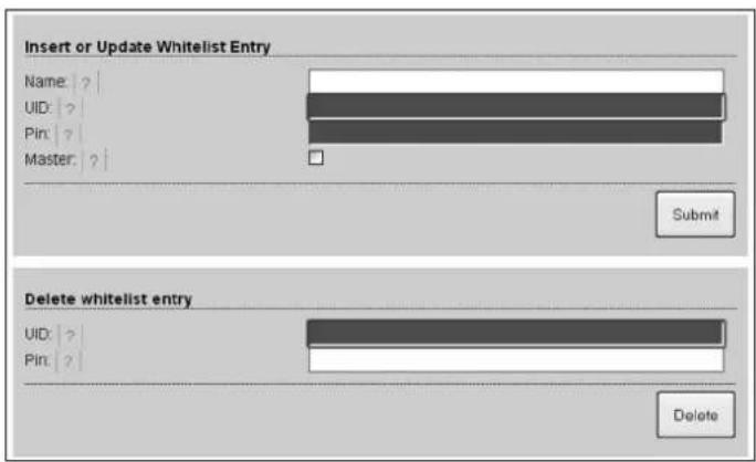
Insert or Update Whitelist Entry Name: ? UID: ? Pin: ? Master: ? Submit Delete whitelist entry UID: Pin: ? DeleteFig. 19: Menu "Whitelist Operation"
The menu "Whitelist Operation" allows you to edit whitelist entries for RFID cards. You can add and delete RFID cards or edit entries.
For this purpose, the UIDs of the RFID cards must be known, as the RFID cards already existing in the whitelist are not shown here.
You can manage the whitelist more conveniently with the Charge APP.
Adding / editing an RFID card
- Enter the name required for the RFID card in the field "Name".
- Enter the UID of the RFID card in the field "UID".
- Enter the PIN 2 (whitelist PIN, see set-up data sheet) of the charging station in the field "PIN".
- Use the checkbox "Master" to choose if the RFID card should be created as a master RFID card.
Master RFID cards cannot be used to start charging processes! - Click on the button "Submit" to add or edit an RFID card.
√ The settings applied to the RFID card have been incorporated into the internal database (whitelist).
Deleting an RFID card
- Enter the UID of the RFID card to be deleted into the field "UID".
- Enter the PIN 2 (whitelist PIN, see set-up data sheet) of the charging station in the field "PIN".
- Click on the button "Delete" to delete the RFID card.
√ The RFID card has been deleted from the internal database (whitelist).
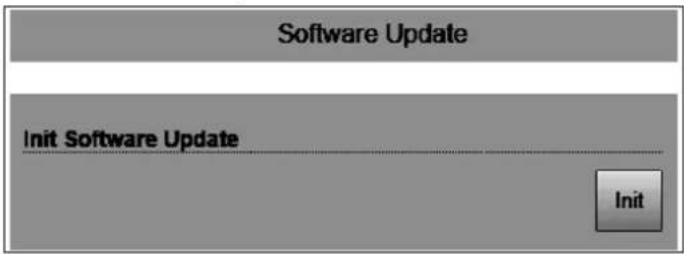
Menu "Software Update"
text_image
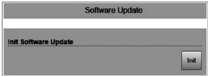
Software Update Init Software Update InitFig. 20: Menu "Software Update"
Use the menu "Software Update" to update the operating software of the charging station.
Proceed as follows to update the operating software of your charging station.
The current operating software can be found in our service area under www.AMTRON.info
- Enter the address www.AMTRON.info into the address bar of your Internet browser.
- Enter the serial number of your charging station in the input field "Access".
- Select Software Update in the "Download" section.
- Download and save the current software (e.g. HC3Application_R2_1_05_421.bin).
- Call up the service interface of your charging station.
- Select the submenu "Software Update" in the main menu.
- Select the previously downloaded software
- Click on the button Upload" to update the software
- Follow the instructions
If the software update is interrupted prematurely (e.g. due to power failure or transmission error), the charging station must be restarted (e.g. by clicking the button "Reset" in the menu "Customer Settings") before a new update can be attempted.
5 Maintenance
Danger
Risk of death resulting from improper maintenance / repair.
There is a risk of injury for persons performing tasks for which they are neither qualified nor have received appropriate training.
■ The maintenance / repair of the device may be performed only by persons who are familiar with this task, have been instructed with regard to the associated hazards and who possess the necessary qualifications.
■ All technical safety conditions have to be satisfied prior to performing maintenance / repairs.
Danger
Risk of death by electric shock!
Components have voltage applied.
Contact with current conducting parts results in an electric shock, burns or death.
When working with the electrical system, the following points must be observed:
■ Disconnect device from voltage.
■ Secure device from being turned back on.
■ Ensure that no voltage is applied.
■ Earth and short-circuit the unit.
■ Cover neighbouring components that are under voltage and secure the danger area.
5.1 Maintenance plan
Carry out the following maintenance work at the specified intervals.
Maintenance interval every 6 months (biannually)
| Part / component Maintenance work | |
| Enclosure Visual inspection for defects or damage. | |
| Check the device for secure fastening. | |
| Clean the outside of the enclosure with damp cloth. | |
| Front panel | Visual inspection for defects or damage. |
| Switching and safety devices | Visual inspection for defects or damage. |
| Check the function of the circuit breaker (CB).See Chapter 4.3.3 on page 11. | |
Maintenance interval every four years
In addition, carry out all maintenance specified in Maintenance interval every 6 months (biannually).
| Part / component Maintenance work | |
| Cable connections and connectors | Visual inspection for defects or damage. |
| Charging station Visual | inspection for defects or damage. |
| Check function | |
| System check Ask a qualified electrician to check the system according to VDE0100. | |
6 Troubleshooting
Danger
Risk of death resulting from improper maintenance / repair.
There is a risk of injury for persons performing tasks for which they are neither qualified nor have received appropriate training.
■ The maintenance / repair of the device may be performed only by persons who are familiar with this task, have been instructed with regard to the associated hazards and who possess the necessary qualifications.
■ All technical safety conditions have to be satisfied prior to performing maintenance / repairs.
Danger
Risk of death by electric shock!
Components have voltage applied.
Contact with current conducting parts results in an electric shock, burns or death.
When working with the electrical system, the following points must be observed:
■ Disconnect device from voltage.
■ Secure device from being turned back on.
■ Ensure that no voltage is applied.
■ Earth and short-circuit the unit.
■ Cover neighbouring components that are under voltage and secure the danger area.
6.1 Troubleshooting by the operator
| Fault | Cause | Notes on troubleshooting | |
| lit red permanently | Self-test of the charging station is faulty. | Acknowledge the fault with multi-function button. | |
| Thermal shutdown of the charging | station. | Wait until the charging station has cooled down. | |
| Internal system error. | Displaying the error message with service interface or Charge APP.Acknowledge the fault with multi-function button.If you cannot rectify the fault, ask a qualified electrician to check the charging station. | ||
| Fault | Cause | Notes on troubleshooting | |
 | Residual current circuit breaker (RCCB) or circuit breaker (CB) in the charging station has tripped. | Re-activate residual current circuit breaker (RCCB) or circuit breaker (CB).→ See Chapter 4.3.2 on page 11. | |
 | Error in the power supply to the charging station (incorrect phase sequence, missing phase, etc.). | Ask a qualified electrician to check the power supply of the charging station. | |
| Charging plug not interlocked. | Disconnect charging cable and plug in again.Acknowledge the fault with multi-function button. | ||
| Incorrect or faulty charging cable. | Disconnect charging cable and plug in again.Check charging cable and replace if necessary.Acknowledge the fault with multi-function button. | ||
| Network error. | Check network or network settings. | ||
| LED info bar does not light up | No power supply to the charging station. | Ask a qualified electrician to check the charging station. | |
| The back-up fuse of the charging station has tripped. | Check back-up fuse and re-activate if necessary. | ||
| Charging plug cannot be removed from the charging station. | Failure of the unlocking function. | Ask a qualified electrician to check the charging station. | |
EN
If you cannot rectify the error or fault, ask a qualified electrician to check the charging station.
7 Disassembly, Storage and Disposal
7.1 Disassembly
Danger
Risk of death by electric shock!
Components have voltage applied.
Contact with current conducting parts results in an electric shock, burns or death.
When working with the electrical system, the following points must be observed:
■ Disconnect device from voltage.
■ Secure device from being turned back on.
■ Ensure that no voltage is applied.
■ Earth and short-circuit the unit.
■ Cover neighbouring components that are under voltage and secure the danger area.
Ask your installer to remove the charging station.
7.2 Storage
The storage spaces must be dry and temperature regulated. See chapter "Ambient conditions" on page 31 for ambient storage conditions.
7.2.1 Ambient conditions
| Ambient temperature | -25 to +40 °C |
| Average temperature over 24 hours | < 35 °C |
| Storage temperature | -25 to +40 °C |
| Altitude max. 2,000 metres above sea level | |
| Relative humidity | max. 95 % (non-condensing) |
7.3 Disposal
The disposal of old devices must comply with the common national and regional laws and regulations. Ecological considerations must be taken into account.
Old devices and batteries cannot be disposed of with household rubbish.
■ Dispose of the device in accordance with the applicable environmental regulations of your country.
■ Dispose of old devices through your specialised dealer.
■ Dispose of old batteries in a recycling bin for old batteries or through the specialised dealer.
■ Dispose of the packaging material in the recycling bin for cardboard, paper and plastic.
8 Appendix
8.1 Accessories
| Part number | Description |
| On request | Channel adapter for cable ducts |
| 36113 | Charging cable Mode 3, 32 A, 3P+N+PE |
| 320011 | Test box |
8.2 Glossary
| Term | Explanation |
| ACU Accounting Control UnitUnit for communicating with SCUs and HCCs of the charging station. | |
| Backend | Data management service |
| CP Control pilot | Name of the plugs and sockets contacts / line, over which the communication data is transmitted. |
| RCCB | Residual current circuit breakerType A = sensitive to pulse currents,Type B = sensitive to universal currents. |
| HC controller MENNEKES designation of the PWM module or charging controller. | |
| Control Panel | MENNEKES E-Mobility Control Panel for controlling up to 64 charging points and managing a customer base.For smaller and local infrastructures,the E-Mobility Control Panel is an alternative to comprehensive software or back-end systems. |
| LS | Circuit breaker |
| Mode 3(IEC 61851) | Charging mode for vehicles with communication interface on charging couplers type 2. |
| PP | Proximity Pilot or Plug PresentContact for determining the current load capacity of the charging cable and activating the immobiliser. |
| PWM | Pulse-width modulationTransmission of communication data |
| Term | Explanation |
| PWM module Element of the charging station (in mode 3 charging) for communicating with the vehicle. | |
| RFID | Radio Frequency IdentificationAutomatic identification and collection of data using electromagnetic waves. |
| SCU Socket Control UnitUnit for controlling a single charging point and for communicating with the vehicle. | |
| Type 2(IEC 62196-2) | Single and three phase charging couplers with identical plug geometry for charging powers from 3.7 to 44 kW AC. |
| UID User IdentifierThe user identification clearly identifies a user at a computer. | |
| URL | Uniform Resource LocatorUniform source addressing in the Internet which contains (among other things) protocol, host, domain, path and file name of an Internet address. |
| Resistance coding | The charging cables feature resistance coding that is analysed by the charging system.The resistance value defines the maximum allowable current of the charging cable.The charging system will reject cables with insufficient current load capacity. |
| Whitelist | Positive list for aligning the user rights |
8.3 Index
A
Accessories....32
Ambient conditions 31
Appendix....32
Assembly....6
C
Charge APP....20
Charging process
power failure....19
terminating....11, 19
Charging without authorisation....17
Configuration....11, 22
Connector systems....4
D
Delivery Contents 6
Disassembly....31
Disposal....31
E
Exterior view....6
F
Firmware update....27
Front panel....7
G
General Information....2
Glossary ....32
H
HC controller....7
|
Identification Plate....5
Index 32
Intended Use....3
L
LED info bar.... 10
M
Maintenance 28
Maintenance plan.... 28
Multi-function button.... 11
0
Operating modes....9, 12
Operating with Charge APP 9
Operation 9
P
Personnel qualification.... 3
electrician 3
Product description.... 3,4
R
Re-activating CB 11
Re-activating RCCB.... 11
Returning Devices.... 3
RFID card
adding 19,27
deleting 27
editing 27
5
Safety....2
Safety Information 3
Software reset 26
Software update.... 27
Storage.... 31
Structure of the Operating Manual.... 2
T
Troubleshooting 10, 19, 29
W
Warranty 3
Over dit document
4.7 MENNEKES Charge APP 20
natural_image
Three-panel image showing a blue electric vehicle charging plug, its internal components, and a connected plug (no visible text or symbols)Afb. 1
text_image
Technical diagram of a mobile phone casing with numbered components for identificationnatural_image
Line drawing of a device with a probe inserted into a socket (no text or symbols)4.7 MENNEKES Charge APP
4.7.1 Voorwaarden
text_image
MENNEKES® Production Settings Installation Settings Customer Settings Whitelist Operation Software UpdateAfb. 14: Hoofdmenu
Menu "Production Settings"
text_image
Production Settings QS Info HMI HW Version: AA-01330 HMI SW Version: 1.006 HMI Type: L HMI IO Status: ? 0110 HMI Temperature Internal [°C]: 28 HMI Temperature External [°C]: 0 HMI Error Code: 0000 RFID Version: TWN4/B1.03/CB1.49/APP1.00 VLAN Version: 03.41021 HCC3 HW Version: ? 30545-AA-00136 HCC3 SW Version: ? 1.05 HCC3 IO-State: ? 110000 HCC3 CP/PP-State : ? C11 HCC3 Error Code: ? 0 AMTRON Operation Mode: ? Remote AMTRON State : ? Paused AMTRON RS485 Address : ? AMTRON Connector Type: Cable Type 2 AMTRON No. of Phases: 3 AMTRON Rated Current [A] : ? 32 AMTRON Serial Number : ? 20200010 AMTRON Order Number : ? 345202 AMTRON External Temperature Sensor Installed: AMTRON Local Fuses Installed: AMTRON Production Settings Write Enabled: false HCC3 Ethernet MAC Address: 7c70bc801024 HCC3 Total Energy [kWh]: 4Afb. 16: Menu "Production Settings"
Menu "Installation Settings"
text_image
Installation Settings Installation Info AMTRON Installation Current [A]: 16 Home Manager Installed: External Tariff Switch Installed: SubmitAfb. 17: Menu "Installation Settings"
Menu "Customer Settings"
text_image
Customer Settings Customer Info AMTRON Customer Current Limitation [A]: ? 32 AMTRON Wallbox Name: ? AMTRON Enable RFID Authorization: ? ✓ Power Fail Continue: ✓ ✓ Autostart Charging: ? ✓ Enable Stop Button: ✓ Color Schema: IDLE - blue, CHARGE - green, WAIT - white, ERROR - red ✓ Enable RFID Beep: ✓ Enable WLAN Communication: ✓ AMTRON Operation Mode: Switch to operation mode "Remote" Submit WLAN Info STA SSID: ? FRTZ/Box STA Connected? true STA Security Mode: ? No security STA Security Key: ? AP Security Mode: WPA2 AES PSK mode AP Channel: 6 AP Country Code: DE Submit Time Info Local Timestamp: ? 1412607779 Currently Sumner: ? ✓ Timezone Offset [Minutes] : ? 60 Submit SW Reset ResetAfb. 18: Menu "Customer Settings"
Menu "Whitelist Operation"
text_image
Insert or Update Whitelist Entry Name: ? UID: ? Pin: ? Master: ? Submit Delete whitelist entry UID: ? Pin: ? DeleteAfb. 19: Menu "Whitelist Operation"
Menu "Software Update"
text_image
Software Update Init Software Update InitAfb. 20: Menu "Software Update"
4.7 Application MENNEKES Charge....20
natural_image
Close-up of a blue electric vehicle charging plug (no visible text or symbols)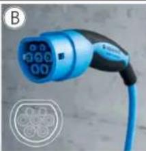
natural_image
Blue electric vehicle charging plug with digital display (no visible text or symbols)
natural_image
Close-up of an electric vehicle charging plug with blue cable and connector (no visible text or symbols)Fig. 1
text_image
Technical diagram of a mobile phone casing with numbered components for identificationnatural_image
Line drawing of a device with a probe inserted into a socket (no text or symbols)4.7 Application MENNEKES Charge
text_image
MENNEKES® Production Settings Installation Settings Customer Settings Whitelist Operation Software UpdateFig. 14 : menu principal
text_image
Production Settings QS Info HMI HW Version: AA-01330 HMI SW Version: 1.006 HMI Type: L HMI IO Status: ? 0110 HMI Temperature Internal [°C]: 28 HMI Temperature External [°C]: 0 HMI Error Code: 0000 RFID Version: TWN4/B1.03/CB1.49/APP1.00 VLAN Version: 03.41021 HCC3 HW Version: ? 30545-AA-00136 HCC3 SW Version: ? 1.05 HCC3 IO-State: ? 110000 HCC3 CP/PP-State: ? C11 HCC3 Error Code: ? 0 AMTRON Operation Mode: ? Remote AMTRON State : ? Paused AMTRON RS465 Address : ? AMTRON Connector Type: Cable Type 2 AMTRON No. of Phases: 3 AMTRON Rated Current [A] : ? 32 AMTRON Serial Number : ? 20200010 AMTRON Order Number : ? 345202 AMTRON External Temperature Sensor Installed: AMTRON Local Fuses Installed: AMTRON Production Settings Write Enabled false HCC3 Ethernet MAC Address: 7c70bc801024 HCC3 Total Energy [Wh]: 4text_image
Installation Settings Installation Info AMTRON Installation Current [A]: 2 | 16 Home Manager Installed: External Tariff Switch Installed: Submittext_image
Customer Settings Customer Info AMTRON Customer Current Limitation [A] | ? 32 AMTRON Wallbox Name : ? AMTRON Enable RFID Authorization : ? ✓ Power Fail Continue: ✓ Autostart Charging : ? ✓ Enable Stop Button: ✓ Color Schema: IDLE - blue, CHARGE - green, WAIT - white, ERROR - red ✓ Enable RFID Beep: ✓ Enable WLAN Communication: ✓ AMTRON Operation Mode: Switch to operation mode "Remote" Submit WLAN Info STA SSID : ? FRITZ/Box STA Connected? true STA Security Mode : ? No security STA Security Key : ? AP Security Mode: WPA2 AES PSK mode AP Channel: 6 AP Country Code : ? DE Submit Time Info Local Timestamp : ? 1412607779 Currently Summer : ? ✓ Timezone Offset [Minutes] : ? 60 Submit SW Reset Resettext_image
Insert or Update Whitelist Entry Name: ? UID: ? Pin: ? Master: ? Submit Delete whitelist entry UID: Pin: ? Deletetext_image
Software Update Init Software Update InitApplication Charge 20
C
natural_image
Three-panel image showing a blue electric vehicle charging plug, its internal circuit diagram, and its wire-wrapped electrical plug (no visible text or symbols)Fig. 1
text_image
Technical diagram of a device casing with numbered components for identificationnatural_image
Line drawing of a device with a probe inserted into a socket (no text or symbols)text_image
MENNEKES® Production Settings Installation Settings Customer Settings Whitelist Operation Software UpdateFig. 14: menu principale
text_image
Time Info Local Timestamp: | ? | 1427191248 Currently Summer: | ? | Timezone Offset [Minutes] | ? | 60 SubmitFig. 15: Menu „Customer Settings / Time Info“
Menu "Production Settings"

text_image
Production Settings QS Info HMI HW Version: AA-01330 HMI SW Version: 1.006 HMI Type: L HMI IO Status: ? 0110 HMI Temperature Internal [°C]: 28 HMI Temperature External [°C]: 0 HMI Error Code: 0000 RFID Version: TWN4/B1.03/CB1.49/APP1.00 VLAN Version: 03.41021 HCC3 HW Version: ? 30546-AA-00136 HCC3 SW Version: ? 1.05 HCC3 IO-State: ? 110000 HCC3 CP/PP-State: ? C11 HCC3 Error Code: ? 0 AMTRON Operation Mode: ? Remote AMTRON State: ? Paused AMTRON RS485 Address: ? AMTRON Connector Type: Cable Type 2 AMTRON No. of Phases: 3 AMTRON Rated Current [A]: ? 32 AMTRON Serial Number: ? 20200010 AMTRON Order Number: ? 345202 AMTRON External Temperature Sensor Installed: AMTRON Local Fuses Installed: AMTRON Production Settings Write Enabled: false HCC3 Ethernet MAC Address: 7c70bc801024 HCC3 Total Energy [kW]: 4Fig. 16: Menu "Production Settings"
Menu "Installation Settings"

text_image
Installation Settings Installation Info AMTRON Installation Current [A]: 16 Home Manager Installed: External Tariff Switch Installed: SubmitFig. 17: menu "Installation Settings"
text_image
Customer Settings Customer Info AMTRON Customer Current Limitation [A]: ? 32 AMTRON Wallbox Name: ? AMTRON Enable RFID Authorization: ? Power Fail Continue: Autostart Charging: ? Enable Stop Button: Color Schema: IDLE - blue, CHARGE - green, WAIT - white, ERROR - red Enable RFID Beep: Enable WLAN Communication: AMTRON Operation Mode: Switch to operation mode "Remote" Submit WLAN Info STA SSID: ? FRTZ/Box STA Connected?: true STA Security Mode: ? No security STA Security Key: ? AP Security Mode: WPA2 AES PSK mode AP Channel: 6 AP Country Code: ? DE Submit Time Info Local Timestamp: ? 1412607779 Currently Summer: ? Timezone Offset [Minutes] ? 60 Submit SW Reset ResetFig. 18: Menu „Customer Settings“
Menu "Whitelist Operation"
text_image
Insert or Update Whitelist Entry Name: ? UID: ? Pin: ? Master: ? Submit Delete whitelist entry UID: ? Pin: ? Deletetext_image
Software Update Init Software Update InitFig. 20: menu „Software Update“
natural_image
Three-panel image showing a blue electric vehicle charging plug, its internal components, and a white cable with a coiled cable (no visible text or symbols)Fig. 1
text_image
Technical diagram of a mobile phone casing with numbered component labelsnatural_image
Line drawing of a device with a probe inserted into a socket (no text or symbols)Fig. 9: Plugge inn ladekabelen (eksempel)
4.5.6 Strømbrudd under lading
Ved spenningsbrudd (strømbrudd) avbrytes ladingen. På ladestasjoner med ladestikkontakt type 2 låses ladepluggen opp og kan trekkes ut. Hvis ladepluggen ikke kan trekkes ut, har en aktuator låst ladepluggen mekanisk.
text_image
MENNEKES® Production Settings Installation Settings Customer Settings Whitelist Operation Software UpdateFig. 14: Hovedmeny
- Velg ønsket undermeny.
For noen parameter finnes et verktøytips med ytterligere informasjon. Pek med musepekeren på "?" på respektive parameter - det er ikke nødvendig å klikke.
4.8.3 Tidssynkronisering
Meny "Production Settings"

text_image
Production Settings QS Info HMI HW Version: AA-01330 HMI SW Version: 1.006 HMI Type: L HMI IO Status: ? 0110 HMI Temperature Internal [°C]: 28 HMI Temperature External [°C]: 0 HMI Error Code: 0000 RFID Version: TWN4/B1.03/CB1.49/APP1.00 VLAN Version: 03.41021 HCC3 HW Version: ? 30546-AA-00136 HCC3 SW Version: ? 1.05 HCC3 IO-State: ? 110000 HCC3 CP/PP-State: ? C11 HCC3 Error Code: ? 0 AMTRON Operation Mode: ? Remote AMTRON State: ? Paused AMTRON RS485 Address: ? AMTRON Connector Type: Cable Type 2 AMTRON No. of Phases: 3 AMTRON Rated Current [A]: ? 32 AMTRON Serial Number: ? 20200010 AMTRON Order Number: ? 345202 AMTRON External Temperature Sensor Installed: AMTRON Local Fuses Installed: AMTRON Production Settings Write Enabled: false HCC3 Ethernet MAC Address: 7c70bc801024 HCC3 Total Energy [kWh]: 4Fig. 16: Meny "Production Settings"
Meny "Installation Settings"
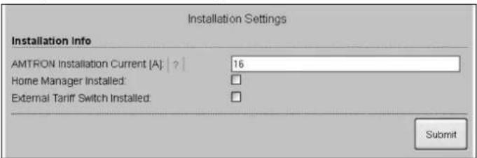
text_image
Installation Settings Installation Info AMTRON Installation Current [A]: 16 Home Manager Installed: External Tariff Switch Installed: SubmitFig. 17: Meny "Installation Settings"
Meny "Customer Settings"
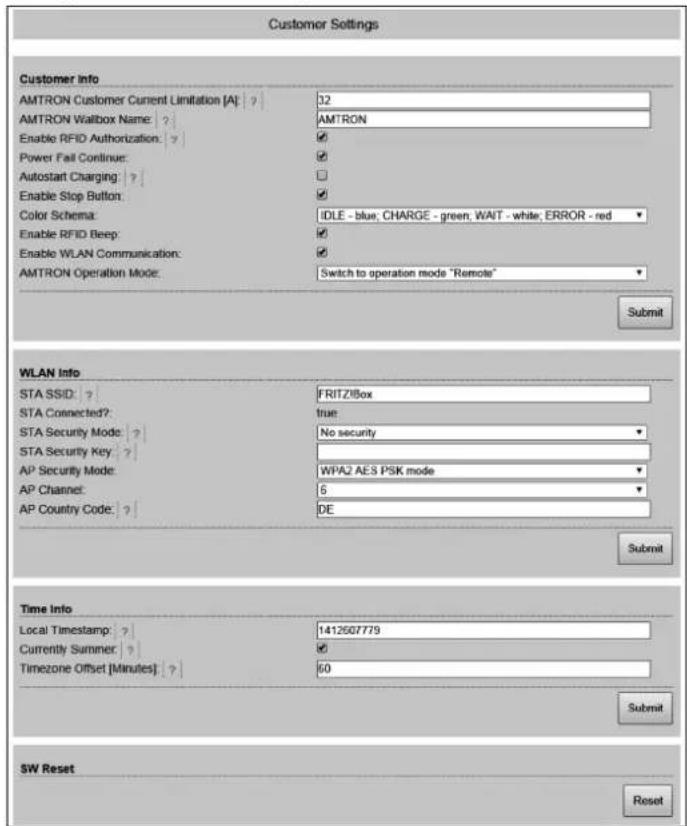
text_image
Customer Settings Customer Info AMTRON Customer Current Limitation [A]: ? 32 AMTRON Wallbox Name: ? AMTRON Enable RFID Authorization: ? ✓ Power Fail Continue: ✓ ✓ Autostart Charging: ? ✓ Enable Stop Button: ✓ Color Schema: IDLE - blue, CHARGE - green, WAIT - white, ERROR - red ✓ Enable RFID Beep: ✓ Enable WLAN Communication: ✓ AMTRON Operation Mode: Switch to operation mode "Remote" Submit WLAN Info STA SSID: ? FRITZ/Box STA Connected?: true STA Security Mode: ? No security STA Security Key: ? AP Security Mode: WPA2 AES PSK mode AP Channel: 6 AP Country Code: ? DE Submit Time Info Local Timestamp: ? 1412607779 Currently Summer: ? Timezone Offset [Minutes] ? 60 Submit SW Reset ResetFig. 18: Meny "Customer Settings"
Meny "Whitelist Operation"
text_image
Insert or Update Whitelist Entry Name: ? UID: ? Pin: ? Master: ? Submit Delete whitelist entry UID: ? Pin: ? DeleteFig. 19: Meny "Whitelist Operation"
Meny "Software Update"
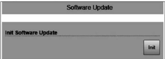
text_image
Software Update Init Software Update InitFig. 20: Meny "Software Update"
All information regarding application areas, product solutions, basic knowledge, training courses and discussion guides can also be found online in our info portal.

natural_image
Exterior view of a white electric car charging station with two Mendenkes-branded stations, no visible text or symbols on the main subjects.Further information can also be found at our website
www.MENNEKES-emobility.de
For questions, please contact your responsible service partner.
Brochures can be requested by sending an e-mail to:
info@MENNEKES-emobility.de
You can also find us at Facebook, YouTube, Twitter, Xing and LinkedIn