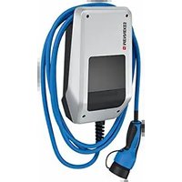
AMTRON Compact 2.0S 11 - Car charger Mennekes - Free user manual and instructions
Find the device manual for free AMTRON Compact 2.0S 11 Mennekes in PDF.

User questions about AMTRON Compact 2.0S 11 Mennekes
0 question about this device. Answer the ones you know or ask your own.
Ask a new question about this device
Download the instructions for your Car charger in PDF format for free! Find your manual AMTRON Compact 2.0S 11 - Mennekes and take your electronic device back in hand. On this page are published all the documents necessary for the use of your device. AMTRON Compact 2.0S 11 by Mennekes.
USER MANUAL AMTRON Compact 2.0S 11 Mennekes
Operating and installation manual
natural_image
Line drawing of an electric vehicle charging station with hoses and control panel (no text or symbols)Inhaltsverzeichnis
8.3 Firmware Update....38
9 Störungsbehebung.... 39
Homepage: https://www.chargeupyourday.com/

Servicepartner
text_image
Diagram of an electric vehicle charging station with numbered components and labeled portstext_image
Labeled diagram of a mobile phone internal structure with numbered componentstext_image
MEANH003 MEANH003 C BND MEANH003 BNDtext_image
L1L2L3N PEAMTRON® Compact 2.0s 22
AMTRON® Compact 2.0s 11
text_image
Technical diagram of a mechanical assembly with labeled components and an arrow pointing to a specific part.text_image
Technical diagram of a device with labeled parts, showing front panel and spring mechanismtext_image
Technical diagram of a device with labeled components, showing front panel and side view with connection points.DE
2 For your safety.... 3
2.1 Target groups.... 3
2.2 Intended use.... 3
2.3 Improper use 3
2.4 Basic safety information.... 4
2.5 Safety labels.... 4
3 Product description...... 6
3.1 Main features 6
3.2 Rating plate 6
3.3 Delivery contents.... 7
3.4 Product structure....7
3.5 Solar charging modes 8
3.6 LED information panel....8
4 Technical data.... 11
5 Installation.... 13
5.1 Select location.... 13
5.1.1 Permissible ambient conditions.... 13
5.2 Preparatory work on site 13
5.2.1 Upstream electrical installation.... 13
5.2.2 Protective devices....14
5.3 Transporting the product.... 14
5.4 Opening the product 15
5.5 Installing the product on the wall..... 15
5.6 Electrical connection 16
5.6.1 Network configurations.... 16
5.6.2 Power supply.... 16
5.6.3 Shunt release....17
5.7 Connecting the data line (Modbus RTU) .... 17
6 Commissioning 19
6.1 Basic settings via DIP switch 19
6.1.1 Configuring the product 19
6.1.2 Setting the maximum charging current ..... 20
6.1.3 Setting up authorisation through RFID ..... 20
6.1.4 Set unbalanced load limitation 20
6.2 Use cases 21
6.2.1 Downgrade.... 21
6.2.2 Blackout protection.... 22
6.2.3 Solar charging 24
6.2.4 Energy management system 28
6.3 Switching on the product ....30
6.4 Testing the product ....30
6.5 More settings....30
6.5.1 Description of the configuration tool .....30
6.5.2 Managing RFID cards.... 31
6.6 Closing the product....32
7 Operation....33
7.1 Authorisation 33
7.2 Charging the vehicle ....33
8 Servicing 35
8.1 Maintenance....35
8.2 Cleaning....36
8.3 Firmware update ....36
9 Troubleshooting...... 37
9.1 Spare parts....37
10 Taking out of service....38
10.1 Storage....38
10.2 Disposal 38
1 About this document
The charging station is hereinafter referred to as "product". This document applies to the following product variants:
■ AMTRON® Compact 2.0s 11
■ AMTRON® Compact 2.0s 22
This document provides information for the qualified electrician and the operator. It contains important instructions for the installation and proper use of the product.
Copyright ©2022 MENNEKES Elektrotechnik GmbH & Co. KG
1.1 Contact
Website: https://www.chargeupyourday.com/

Service partner
If you have questions concerning the product, please contact your responsible service partner. On our website under “Search for Partners” you will find qualified contacts in your region.
MENNEKES
Please use the form on our website under "Contact" to contact MENNEKES directly.
FAQ
Further information on the subject of electromobility is provided on our website under “FAQ”.
1.2 Warning notices
Warning of personal injury

DANGER
This warning notice indicates imminent danger that will result in death or severe injuries.

WARNING
This warning notice indicates a dangerous situation that can result in death or severe injuries.

CAUTION
This warning notice indicates a dangerous situation that can result in minor injuries.
Warning of material damage

ATTENTION
This warning notice indicates a dangerous situation that can result in material damage.
1.3 Symbols used

The activities marked with this symbol may only be carried out by a qualified electrician.

This symbol indicates an important note.

This symbol is used to point out supplemental, useful information.
This document provides information for the qualified electrician and the operator. Knowledge of electrical engineering is required for certain tasks. These tasks, which are identified by the “qualified electrician” symbol, should only be carried out by a qualified electrician.
“1.3 Symbols used” [▶ 2]
Operators
The operator is responsible for ensuring compliance with the intended use of the product and its safe operation. This also includes instructing persons who use the product. The operator is responsible for ensuring that tasks that require specialist knowledge are completed by an accordingly qualified professional.
Qualified electricians
A qualified electrician is a person who, based on his or her professional education, knowledge and experience as well as knowledge of relevant provisions, can assess the work assigned to him or her and identify possible hazards.
2.2 Intended use
The product is intended for use in private areas.
The product is intended exclusively for the charging of electric and hybrid vehicles, hereinafter referred to as “vehicle”.
■ Charging according to Mode 3 pursuant to IEC 61851 for vehicles with non-gassing batteries.
■ Plugs and sockets according to IEC 62196.
Vehicles with gassing batteries cannot be charged. The product is intended exclusively for permanent wall mounting or mounting on a stand system provided by MENNEKES (e.g. pole), for indoor and outdoor use.
In some countries, there is a requirement for a mechanical switching element to disconnect the charging point from the mains if a load contact on the product is welded (welding detection). The requirement can be implemented, for example, by means of a shunt release.
The product may only be operated taking into account all international and national regulations. Observe the following international regulations or the respective national transposition:
IEC 61851-1
IEC 62196-1
IEC 60364-7-722
IEC 61439-7
When delivered, the product meets the minimum requirements of the European standards for charging point identification in accordance with EN 17186. Some countries have additional national requirements, which must also be observed.
Read, observe and retain this document and all additional documents for this product and, if necessary, pass them on to the subsequent operator.
2.3 Improper use
Using the product is safe only when used as intended. Any other use or changes to the product are considered improper use and therefore not permitted.
The operator, qualified electrician or user is responsible for any personal injury or material damage arising from improper use. MENNEKES Elektrotechnik GmbH & Co. KG accepts no liability for any consequences arising from improper use.
2.4 Basic safety information
Knowledge of electrical engineering
Knowledge of electrical engineering is required for certain tasks. These tasks, which are identified by the “qualified electrician” symbol, must only be carried out by a qualified electrician.
“1.3 Symbols used” [▶ 2]
People can be seriously injured or killed if work that requires knowledge of electrical engineering is carried out by electrical laypersons.
▶ Arrange for work that requires knowledge of electrical engineering to be carried out only by a qualified electrician.
Pay attention to the symbol “Qualified electrician” in this document.
Do not use a damaged product
People can be seriously injured or killed if a damaged device is used.
▶ Do not use a damaged product.
▶ Mark a damaged product to ensure that no one uses it.
▶ Arrange for a qualified electrician to rectify the damage without delay.
▶ Take the product out of service if necessary.
Carry out maintenance properly
Improper maintenance can affect the safety of the product and cause accidents. This can seriously injure or kill people.
▶ Carry out maintenance properly.
“8.1 Maintenance” [▶ 35]
Pay attention to supervisory duties
Individuals who are not fully able to assess potential hazards as well as animals pose a danger to themselves and others.
▶ Keep persons at risk away from the product, e.g. children.
▶ Keep animals away from the product.
Proper use of charging cable
Improper handling of the charging cable can cause hazards such as electric shock, short circuit or fire.
▶ Avoid loads and impacts.
▶ Do not pull the charging cable over sharp edges.
▶ Do not allow the charging cable to become knotted and avoid kinks.
▶ Do not use adapter plugs or extension cables.
▶ Unroll the charging cable completely when charging.
▶ Do not expose the charging cable to tensile stress.
▶ Pull the charging plug from the charging socket.
▶ After using the charging cable, put the protective cap on the charging plug.
2.5 Safety labels
Safety labels that warn of hazardous situations are affixed on some of the product components. If the instructions on the safety labels are not complied with severe or fatal injuries can occur.
Safety labels Meaning
Danger – high voltage.
▶ Prior to working on the product, ensure that it is de-energised.

Danger if the instructions in the accompanying documents are not complied with.
Read the accompanying documents before working on the product.
▶ Comply with the instructions on the safety labels.
▶ Keep safety labels legible.
▶ Replace damaged or illegible safety labels.
If it is necessary to replace a component on which a safety sticker is attached, ensure that the safety sticker is also attached to the new component. The safety sticker must be attached later if necessary.
EN
3 Product description
3.1 Main features
General
■ Mode 3 charging according to IEC 61851
■ Plug and socket according to IEC 62196
■ Max. charging power (AMTRON® Compact 2.0s 11): 11 kW
■ Max. charging power (AMTRON® Compact 2.0s 22): 22 kW
■ Connection: single phase / three phase
■ Max. charging power configurable by qualified electrician
■ Status information via LED information panel
■ Sleep mode for reduced standby consumption (approx. 1 W)
■ Permanently connected charging cable type 2 (7.5 m)
■ Integrated cable hanger
■ Enclosures made of AMELAN®
Authorisation options
■ Autostart (without authorisation)
■ RFID (ISO / IEC 14443 A)
compatible with MIFARE classic and MIFARE DESFire
Options for local load management
■ Reduction of the charging current using an external switching contact (downgrade input)
■ Reduction of the charging current in case of uneven phase load (unbalanced load limitation)
■ Solar charging through an upstream, external energy meter
■ Single-phase and three-phase solar charging for charging powers of 1.4 to 11 kW (AMTRON® Compact 2.0s 11)
■ Three-phase solar charging for charging powers of 4.2 to 22 kW (AMTRON® Compact 2.0s 22)
■ Local blackout protection by an upstream, external energy meter
Options for connecting to an external energy management system (EMS)
Via Modbus RTU
Integrated protective devices
■ No integrated residual current device
■ No integrated circuit breaker
■ DC residual current monitoring > 6 mA in accordance with IEC 62955
■ Switching output for controlling an external shunt release, in order to disconnect the charging point voltage from the mains in case of a fault (welded load contact, welding detection)
3.2 Rating plate
The rating plate contains all important product data.
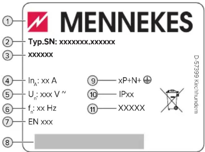
text_image
MENNEKES Typ.SN: xxxxxxx.xxxxxxx xxxxxx In_A: xx A U_n: xxx V ~ f_n: xx Hz EN xxx 9 — xP+N+ 10 — IPxx 11 — XXXXX D-57399 KirchhundernFig. 1: Rating plate (example)
1 Manufacturer
2 Type number / serial number
3 Type designation
4 Rated current
5 Rated voltage
6 Rated frequency
7 Standard
8 Barcode
9 Number of poles
10 IP rating
11 Use
3.3 Delivery contents
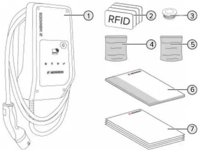
text_image
RFID 1 2 3 4 5 6 7Fig. 2: Delivery contents
1 Product
2 4 RFID cards (3 user and 1 master card; when delivered, the RFID cards have already been programmed in the local whitelist)
3 6 membrane glands
4 Bag with installation materials (screws, dowels, sealing plugs)
5 Bag with materials to connect the data line (1 shield clamp, 2 cable ties)
6 Operating and installation manual
7 Additional documents:
■ "DIP switch" supplement
■ Drilling template (printed and perforated on cardboard box insert)
■ Circuit diagram
■ Test certificate
For the product variant AMTRON® Compact 2.0s 22, an M25 / M32 adapter, locknut and M32 screw connection are included for connecting the supply line with an outer diameter ≥ 17 mm.
3.4 Product structure
Exterior view
text_image
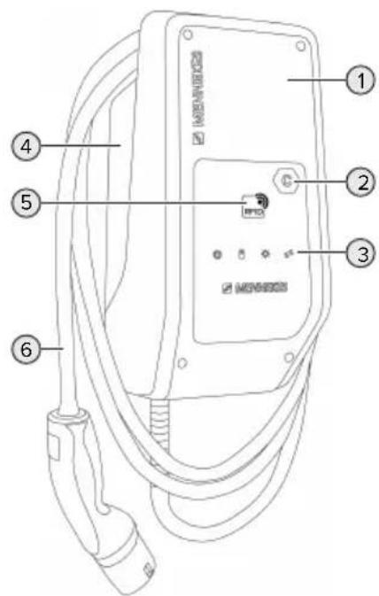
Diagram of an electric vehicle charging station with numbered components and labeled connectorsFig. 3: Exterior view
1 Top section of housing
2 Charging point marking according to EN 17186
3 LED information panel
4 Bottom section of housing
5 RFID card reader
6 Charging cable
EN
Inside view
text_image
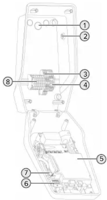
Technical diagram of an electronic device with numbered components for identificationFig. 4: Inside view
1 Cable glands *
2 Solar button
3 Terminals
■ 3 and 4: Downgrade input
■ 5 and 6: External shunt release switching output
4 Terminals to connect the data line (for Modbus RTU)
5 MCU (MENNEKES Control Unit)
6 DIP switch
7 Connection for the MENNEKES configuration lead
8 Terminals for voltage supply
* Additional cable glands are located on the top and bottom.
3.5 Solar charging modes
Requirements:
√ The product is connected to an external energy meter via Modbus RTU and correctly configured. The energy meter captures the excess electricity from the photovoltaic system.
“6.2.3.2 Connection and configuration” [▶ 27]
√ Solar charging is activated.
“6.1 Basic settings via DIP switch” [▶ 19]
√ AMTRON® Compact 2.0s 22: The product is connected to three-phase voltage.
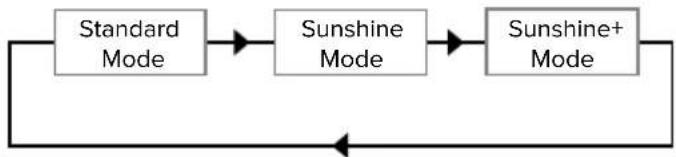
The product has 3 charging modes (Standard mode, Sunshine mode, Sunshine+ mode).
Standard mode
Charging occurs at maximum power. Mains power is used for charging unless there is a sufficient amount of excess energy.
Sunshine mode
The charging power is dependent on the excess energy from the photovoltaic system. Solar energy exclusively is used for charging. The charging process starts if there is a sufficient amount of energy available to charge the vehicle at 6 A per phase.
Sunshine+ mode
The charging power is dependent on the excess energy from the photovoltaic system. Regardless of how much current the photovoltaic system is feeding at the time, the vehicle is provided with minimum charging current at all times (if necessary through mains power). The minimum charging current (standard: 6 A per phase) can be adjusted using the configuration tool (a qualified electrician is required).

Detailed information regarding the Sun-shine mode and Sunshine+ mode can be found in chapter:
“6.2.3 Solar charging” [▶ 24]
3.6 LED information panel
The LED information panel shows the operating status of the product (e.g. standby, fault).
Standby
| Symbol Meaning | |
| lights up | The product is ready for use. No vehicle is connected to the product. |
| flashes slowly | Not all requirements for charging are met, e.g.■ The authorisation process is complete. No vehicle is connected to the product.■ A vehicle is connected to the product. The charging process is prevented for a reason (e. g. active downgrade input is configured for 0 A or there is a command from the energy management system) |
| flashes rapidly | A vehicle is connected to the product. Authorisation has not occurred. |
| flashes once | The presented RFID card has been added to the whitelist (in Teach mode). |
Colour of the symbol: blue or green (dependent on the configuration)
In Standby operating mode, the product can switch to Sleep mode after 10 minutes to reduce internal consumption. The Sleep mode is configurable and is enabled in the delivery state. It is terminated by plugging in the charging cable or by an authorisation. In Sleep mode, no symbol lights up on the LED information panel.
Charging
Symbol Meaning
lights up The charging process runs.
| Symbol | Meaning |
| flashes slowly | The operating temperature is very high. The charging process runs. The charging current is reduced to avoid overheating and shutting down the product. |
| flashes rapidly | The operating temperature has been exceeded. Charging process paused. |
| pulsates | Charging process paused. All requirements for charging a vehicle are met. The charging process is paused due to vehicle feedback or was terminated by the vehicle. |
Colour of the symbol: blue or green (dependent on the configuration)
Sun
Symbol Meaning

lights up The product is in "Sunshine mode".
pulsates The product is in "Sunshine+ mode".
flashes The Teach mode for RFID cards is enabled (for 60 seconds).
Colour of the symbol: white
Fault
Symbol Meaning

lights up There is a fault that is preventing the vehicle from charging. The fault can only be rectified by a qualified electrician.
Symbol Meaning

| flashes There is a fault that is preventing the vehicle from charging. The fault can be rectified by reconnecting the charging plug or by cooling down the product. | |
| flashes once | ■ The presented RFID card is not included in the whitelist. Authorisation has not occurred.■ All RFID cards have been removed from the whitelist (master RFID card presented for 10 seconds).■ The presented RFID card has been removed from the whitelist (in Teach mode). |
| flashes three times | The RFID card memory is full (max. 10 RFID cards). |
“9 Troubleshooting” [▶ 37]
Colour of the symbol: red
4 Technical data
| AMTRON® Compact 2.0s 11 AMTRON® Compact 2.0s 22 | |
| Max. charging power [kW] 11 22 | |
| Rated current I_nA [A] 16 32 | |
| Rated current of a charging point Mode 3 I_nC [A] | 16 32 |
| Max. back-up fuse [A] 20 * 40 * | |
| Conditional rated short-circuit current I_cc [kA] | 1.1 1.8 |
* For the design of the maximum back-up fuse, the regulations applicable at the installation site must be observed.
| AMTRON® Compact 2.0s 11, AMTRON® Compact 2.0s 22 | |
| Connection single phase / three phase | |
| Nominal voltage UN [V] AC ±10 % 230 / 400 | |
| Nominal frequency fN [Hz] 50 | |
| Nominal insulation voltage Ui [V] 500 | |
| Nominal impulse withstand voltage Uimp [kV] 4 | |
| Nominal diversity factor RDF 1 | |
| Types of system earthing TN / TT (IT under certain conditions) | |
| EMC classification A+B | |
| Protection class | I |
| IP rating | IP 44 |
| Overvoltage category | III |
| Mechanical impact protection | IK10 |
| Contamination rating | 3 |
| Installation | Outdoor or indoor |
| Stationary / movable | Stationary |
| Use (according to IEC 61439-7) | AEVCS |
| External design | Wall mounted |
| Dimensions H x W x D [mm] | 360.5 x 206.9 x 145.6 |
| Weight [kg] | 4.7 (for products with 11 kW); 6.4 (for products with 22 kW) |
| Standard | IEC 61851, IEC 61439-7 |
The specific standards according to which the product was tested can be found in the declaration of conformity for the product.
| Supply line terminal strip | |||
| Number of terminals 5 | |||
| Conductor material Copper | |||
| Min. Max. | |||
| Clamping range [mm2] rigid 0.2 10 | |||
| flexible 0.2 10 | |||
| with ferrule 0.2 6 | |||
| Tightening torque [Nm] 0.8 1.6 | |||
| Downgrade input terminals | |||
| Number of terminals 2 | |||
| Specification of the external switching contact Potential-free (NC) | |||
| Min. Max. | |||
| Clamping range [mm2] rigid 0.5 4 | |||
| flexible 0.5 4 | |||
| with ferrules 0.5 2.5 | |||
| Tightening torque [Nm] - - | |||
| Switching output for shunt release terminals | |||
| Number of terminals 2 | |||
| Max. switching voltage [V] AC 230 | |||
| Max. switching voltage [V] DC 24 | |||
| Max. switching current [A] 1 | |||
| Min. Max. | |||
| Clamping range [mm2] rigid 0.5 4 | |||
| flexible 0.5 4 | |||
| with ferrules 0.5 2.5 | |||
| Tightening torque [Nm] - - | |||
| Modbus RTU terminals | |||
| Number of terminals 3 x 2 | |||
| Min. Max. | |||
| Clamping range [mm2] rigid 0.5 4 | |||
| flexible 0.5 4 | |||
| with ferrules 0.5 2.5 | |||
| Tightening torque [Nm] - - | |||
5 Installation
5.1 Select location
Requirement(s):
√ Technical data and mains data are the same.
“4 Technical data” [▶ 11]
√ Permissible ambient conditions are observed.
√ The product and the charging station are in sufficient proximity to each other, depending on the length of the charging cable used.
√ The following minimum clearances to other objects (e.g. walls) must be complied with:
■ Distance to left and right: 300 mm
■ Distance above: 300 mm
5.1.1 Permissible ambient conditions
DANGER
Risk of explosion and fire
If the product is operated in potentially explosive areas (ex areas), explosive substances may be ignited by sparking of product components. There is a risk of explosion and fire.
Do not use the product in potentially explosive atmospheres (e.g. gas filling stations).
ATTENTION
Material damage due to unsuitable ambient conditions
Unsuitable ambient conditions can damage the product.
▶ Protect the product from a direct water jet.
▶ Avoid direct sunlight.
▶ Ensure adequate ventilation of the product. Adhere to minimum distances.
▶ Keep the product away from heat sources.
▶ Avoid large temperature fluctuations.
| Permissible ambient conditions | ||
| Min. Max. | ||
| Ambient temperature [°C] -30 +50 | ||
| Average temperature over 24 hours [°C] | +35 | |
| Altitude [m above sea level] 2,000 | ||
| Relative humidity (non-condensing) [%] | 95 | |
EN
5.2 Preparatory work on site
5.2.1 Upstream electrical installation

The tasks described in this section may only be carried out by a qualified electrician.
DANGER
Fire hazard due to overload
If the upstream electrical installation is flawed (e.g. supply line), there is a fire hazard.
▶ Design the upstream electrical installation according to the applicable regulatory standards and the technical data and configuration of the product.
“4 Technical data” [▶ 11]
![Mennekes AMTRON Compact 2.0S 11 - “4 Technical data” [▶ 11] - 1](/content/2026/04/708698/images/1f27bdd5e4d8903aa9c3236087b044ec0b4dc53fe3fa9c48ecd2b20d3ff517bb.jpg)
When configuring the supply line (cross section and cable type), give due consideration to the following local conditions:
■ Type of installation
■ Line length
Route the supply line and the control / data line, if applicable, to the desired location.
The requirements for the data line (e.g. connecting to an external energy meter or energy management system) can be found in chapter:
“5.7 Connecting the data line (Modbus RTU)” [▶ 17]
Installation options
On a wall
■ On the pole from MENNEKES
Wall mounting:
The supply line must be positioned using the drilling template provided or the figure "Drilling dimensions [mm]".
“5.5 Installing the product on the wall” [▶ 15]
Pedestal mounting:
This is available from MENNEKES as an accessory.
See installation manual for the pedestal
5.2.2 Protective devices

The tasks described in this section may only be carried out by a qualified electrician.
The following conditions must be met when installing the protective devices in the upstream electrical installation:
Residual current device

■ National regulations must be observed (e.g. IEC 60364-7-722 (in Germany DIN VDE 0100-722)).
A differential current sensor for DC residual current monitoring > 6 mA in accordance with IEC 62752 is integrated in the product.
The product must be protected by a residual current circuit breaker. As a minimum, a type A residual current circuit breaker must be used.
■ No other circuits may be connected to the residual current circuit breaker.
Supply line fuse (e.g. miniature circuit breaker, NH fuse)

■ National regulations must be observed (e.g. IEC 60364-7-722 (in Germany DIN VDE 0100-722)).
The fuse for the supply line must be designed for the product, taking account, among other considerations, of the rating plate, the required charging power and the supply line (line length, cable cross-section, number of outer conductors, selectivity).
■ The following applies for AMTRON® Compact 2.0s 11: The rated current of the fuse for the supply line must not exceed 20 A (with C characteristics).
The following applies for AMTRON® Compact 2.0s 22: The rated current of the fuse for the supply line must not exceed 40 A (with C characteristics).
Shunt release
▶ Check whether a shunt release is legally prescribed in the country of use.
“2.2 Intended use” [▶ 3]
“2.2 Intended use” [▶ 3]

■ The shunt release must be positioned next to the line circuit breaker.
■ The shunt release and the line circuit breaker must be compatible with each other.
5.3 Transporting the product
ATTENTION
Material damage due to improper transportation
Collisions and impacts may damage the product.
▶ Avoid collisions and impacts.
▶ Transport the product to the place of installation in the packed condition.
▶ Set the product down on a soft base.
5.4 Opening the product

The tasks described in this section may only be carried out by a qualified electrician.
text_image
Technical diagram of an electric vehicle charging station with labeled components and wiring connectionsFig. 5: Opening the product
When delivered, the upper section of the housing is not attached with screws. The screws are included in the delivery contents.
▶ Unscrew screws if necessary.
▶ Fold the top section of the housing downward.
5.5 Installing the product on the wall

ATTENTION
Material damage due to uneven surface
Installing on an uneven surface can cause the housing to go out of shape, so that the protection class is no longer guaranteed. Consequential damage of electronic components can occur.
▶ Only install the product on an even surface.
If necessary, level out uneven surfaces with suitable measures.

MENNEKES recommends installing at an ergonomically sensible height depending on the height of the body.

The fastening materials provided (screws and dowels) are only suitable for installation on concrete, brick or wooden walls.

ATTENTION
Material damage due to drilling dust
Consequential damage of electronic components can occur if drilling dust gets into the product.
▶ Make sure that drilling dust does not get into the product.
▶ Do not use the product as a drilling template and do not drill through the product.
▶ Create the drill holes using the drilling template (included in the delivery contents) or first mark the drill holes using the illustration “Drilling dimensions [mm]” and then drill them. The diameter of the holes depends on the chosen mounting hardware.
text_image
110 5.5 60 10.5 250 290 300 55 5.5 140Fig. 6: Drilling dimensions [mm]
▶ Using a suitable tool, break out the required cable entry point at the predetermined location.
▶ Insert the compatible membrane gland (included in delivery) into the respective cable entry point.
| Cable entry point Membrane gland | |
| Top side and bottom side | Membrane gland with strain relief |
| Rear side Membrane gland | without strain relief |
| For AMTRON® Compact 2.0s 22 and supply line with an outer diameter ≥ 17 mm only: top side and bottom side | ■ M25 / M32 adapter■ Locknut■ M32 screw connectionTightening torque: 3 Nm |
▶ Insert the supply line into the product through the respective cable entry point together with the control / data line (if applicable).

Approx. 30 cm of cable are required for the supply line inside the product.
▶ Fasten the product to the wall using dowels, screws and sealing plugs. Select the tightening torque according to the building material of the wall.

ATTENTION
Material damage due to missing sealing plugs
If the screws in the housing are not covered, or are not adequately covered with the sealing plugs provided, the specified protection class is no longer guaranteed. This can lead to consequential damage of electronic components.
▶ Cover the screws in the enclosure with the provided sealing plugs.
▶ Check the product for firm and secure attachment.
5.6 Electrical connection

The tasks described in this section may only be carried out by a qualified electrician.
5.6.1 Network configurations
The product can be connected in a TN / TT network.
The product can only be connected in an IT network under the following conditions:
√ Connection to a 230 / 400 V IT network is not permitted.
√ Connection to an IT network with 230 V external line voltage over a residual current circuit breaker is permissible, provided that the maximum contact voltage does not exceed 50 V AC when the first error occurs.
5.6.2 Power supply
text_image
L1L2L3NPEFig. 7: Power supply connection
▶ Strip the supply line.
▶ Strip the conductors 10 mm.

When routing the supply line, comply with the permissible bending radius.
Single-phase operation
▶ Connect the conductors of the supply line to the terminals L1, N and PE as per the terminal labelling.
▶ Comply with the connection data for the terminals.

"4 Technical data" [▶ 11]
Three-phase operation
Connect the conductors of the supply line to the terminals L1, L2, L3 N and PE as per the terminal labelling.
▶ Comply with the connection data for the terminals.
“4 Technical data” [▶ 11]
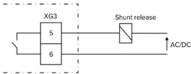
5.6.3 Shunt release
Requirement(s):
√ The shunt release is installed in the upstream electrical installation.
"5.2.2 Protective devices" [▶ 14]
flowchart
graph LR
    A["XG3"] --> B["5"]
    A --> C["6"]
    B --> D["Shunt release"]
    C --> D
    D --> E["AC/DC"]
Fig. 8: Schematic circuit diagram: Connection of an external shunt release
▶ Strip the cable.
▶ Strip the conductors 10 mm.
▶ Connect the conductors to terminals 5 and 6 (XG3).
| Terminal(XG3) | Connection |
5 Shunt release
6 Power supply
■ Max. 230 V AC or max. 24 V DC
Max. 1 A
▶ Comply with the connection data for the switching output.
“4 Technical data” [▶ 11]

In the event of a fault (welded load contact), the shunt release is activated and the product is disconnected from the mains.
5.7 Connecting the data line (Modbus RTU)

The tasks described in this section may only be carried out by a qualified electrician.
EN
The product can be connected to an external energy meter or an energy management system via Modbus RTU.
MENNEKES recommends using the data lines below:
■ With a line length of 40 m, a network cable (CAT-6 / CAT-7) can be used. It can be useful to use a network cable so that your installation is ready to accommodate future developments. Not all wires are required.
■ PROFIBUS cable
For installation in the ground: Siemens PROFIBUS line, underground cable 6XV1830-3FH10 (manufacturer EAN 4019169400428)
For installation without mechanical stress: Siemens PROFIBUS line 6XV1830-0EH10 (manufacturer EAN 4019169400312)
Data lines must not exceed a length of 100 m.
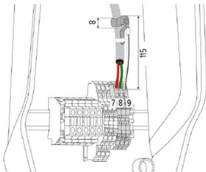
Connection
A shield clamp and two cable ties are needed to connect the data line. These are included in the delivery contents.
text_image
8 115 7 8 9Fig. 9: Data line connection [mm]
Attach shield clamp:
▶ Strip the data line by 8 mm at a length of 115 mm.
▶ Attach the shield clamp at the stripped point.
▶ Use a cable tie to fix the shield clamp in place at the jacket.
Connect the data line:
▶ Strip the data line.
▶ Strip the conductors 10 mm.
▶ Connect the protective shield to terminal 9 (XG2).
▶ Connect the twisted-pair cables to terminals 7 and 8 (XG2).
| Terminal (XG2) Connection | |
| 7 | A |
| 8 | B |
| 9 GND (earth) | |
▶ Comply with the connection data.
“4 Technical data” [▶ 11]
▶ Use a cable tie to fix all wire pairs in place.
▶ Insulate the used wire pairs (contact guard).
Attaching termination resistors at the ends of the data line (optional)
If it is not possible to establish a stable connection with the Modbus subscribers, we recommend terminating both ends of the data line using 120 Ohm resistors. Terminating the ends will reduce reflections and increase communication stability. The need for terminating the ends of wires is dependent on the installation environment (e.g. cable length, number of Modbus subscribers). A general specification regarding the use of termination resistors can therefore not be provided.
6 Commissioning
6.1 Basic settings via DIP switch

Changes made via the DIP switches only take effect after restarting the product.
▶ Disconnect product from voltage if necessary.
6.1.1 Configuring the product

The tasks described in this section may only be carried out by a qualified electrician.
In the top section of the housing, there are two 8-pin DIP switches, with which the device can be configured. In the delivery state, all DIP switches are switched off ("OFF"). On delivery, the product is ready for connection.
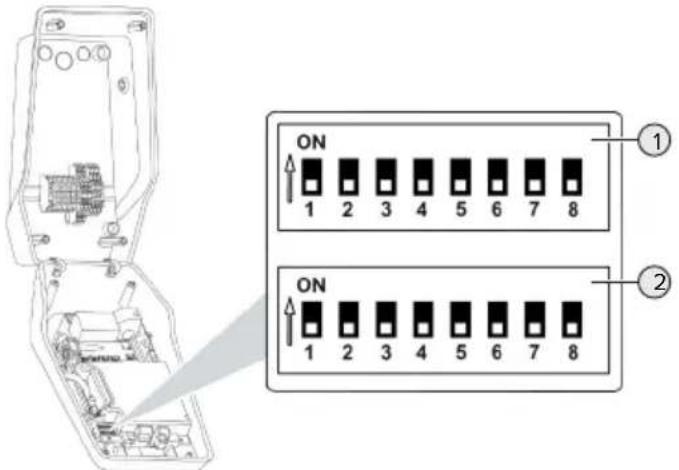
text_image
ON 1 2 3 4 5 6 7 8 ① ON 1 2 3 4 5 6 7 8 ②Fig. 10: DIP switch (delivery state)
1 Bank S1
2 Bank S2
The following functions can be set via the DIP switches:
Bank S1
| DIP switch | Function |
| 1 LED display colour scheme■ "OFF": ■ "Standby" symbol = blue ■ "Charging" symbol = green ■ "ON": ■ "Standby" symbol = green ■ "Charging" symbol = blue | |
| 2 Unbalanced load limitation■ "OFF": Unbalanced load limitation off ■ "ON": Unbalanced load limitation on | |
| 3 Authorisation■ "OFF": No authorisation (Autostart) ■ "ON": Authorisation through RFID | |
| 4 Using Modbus RTU■ "OFF": Modbus RTU is not used ■ "ON": Modbus RTU is used | |
| 5 Master / Satellite■ "OFF": Configuration as master ■ "ON": Configuration as satellite | |
| 6 Type of energy meter■ "OFF": Siemens PAC1600 7KT1661 ■ "ON": TQ Energy Manager EM 420 | |
| 7 Solar charging■ "OFF": Solar charging deactivated ■ "ON": Solar charging activated | |
| 8 Without function | |
Bank S2
| DIP switch | Function |
| 1, 2, 3 Max. charging current | |
| 4, 5 Reduced charging current when down-grade input is energised | |
| 6,7,8 Max. amperage - building connection | |
6.1.2 Setting the maximum charging current

The tasks described in this section may only be carried out by a qualified electrician.
The maximum charging current of the charging point can be set via DIP switches 1, 2 and 3 on bank S2.
AMTRON® Compact 2.0s 22
The maximum charging current can be set to 6 A, 10 A, 13 A, 16 A, 20 A, 25 A or 32 A.
| DIP switch setting (bank S2) Max. char- | ging cur-rent [A] | ||
| 1 2 3 | |||
| OFF OFF OFF 32 | |||
| ON OFF OFF 25 | |||
| OFF ON OFF 20 | |||
| ON ON OFF 16 | |||
| OFF OFF ON 13 | |||
| ON OFF ON 10 | |||
| OFF ON ON 6 | |||
The settings ON – ON – ON are invalid for configuring the maximum charging current (operating state "Fault"). If these settings are selected, a new master RFID card can be programmed ("taught").
“6.5.2 Managing RFID cards” [▶ 31]
AMTRON® Compact 2.0s 11
The maximum charging current can be set to 6 A, 10 A, 13 A or 16 A.
| DIP switch setting (bank S2) Max. char- | ging cur-rent [A] | ||
| 1 2 3 | |||
| OFF OFF OFF 16 | |||
| ON OFF OFF 16 | |||
| OFF ON OFF 16 | |||
| ON ON OFF 16 | |||
| OFF OFF ON 13 | |||
| ON OFF ON 10 | |||
DIP switch setting (bank S2) Max. char-
| 123 | ging current [A] | ||
| OFF ON ON 6 | |||
The settings ON – ON – ON are invalid for configuring the maximum charging current (operating state "Fault"). If these settings are selected, a new master RFID card can be programmed ("taught").
“6.5.2 Managing RFID cards” [▶ 31]
6.1.3 Setting up authorisation through RFID

The tasks described in this section may only be carried out by a qualified electrician.
Authorisation occurs through an RFID card and a local whitelist. Up to 10 RFID cards can be managed in the whitelist. The RFID cards included in the delivery contents are already programmed and included in the local whitelist.
▶ Set DIP switch 3 on bank 1 to "ON".
6.1.4 Set unbalanced load limitation

The tasks described in this section may only be carried out by a qualified electrician.
Unbalanced load refers to the uneven loading of the phases of a three-phase alternating current network. An unbalanced load must be avoided if the vehicle is charged with one or two phases. In Germany, for example, an unbalanced load exists if the difference between two phases at the mains connection point is greater than 20 A (in accordance with VDE-N-AR-4100).
▶ Observe applicable national regulations.
▶ Set DIP switch 2 on bank S1 to "ON".
⇒ The unbalanced load is limited to 20 A (default setting).
To limit the unbalanced load to a different current value, the configuration tool is required.
“6.5.1 Description of the configuration tool” [▶ 30]
Unbalanced load limitation when connecting an external energy meter
When connecting an external energy meter, the charging station regulates the charging current while taking into account all the connected consumers.
6.2 Use cases
6.2.1 Downgrade

The tasks described in this section may only be carried out by a qualified electrician.
By using the downgrade input, it is possible to reduce the grid connection charging current that is not available at its maximum level under certain circumstances or at certain times. For example, the downgrade input can be controlled by the following criteria or control systems:
Electricity rate
■ Clock position
Load shedding
■ Manual control
■ External load management
| Switching contact status | Downgrade status |
| open Downgrade active | |
| closed Downgrade inactive | |
Electrical connection of the switching contact

ATTENTION
Material damage due to improper installation
Improper installation of the switching contact can damage the product or lead to malfunctions. Observe the following requirements during the installation:
▶ Select suitable cable routing to avoid interference.
In the delivery state, a jumper is inserted on the downgrade input. This must be removed first.
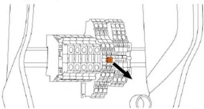
text_image
Technical diagram of a mechanical assembly with labeled components and an arrow pointing to a specific part.Fig. 11: Removing the jumper
Remove the jumper.
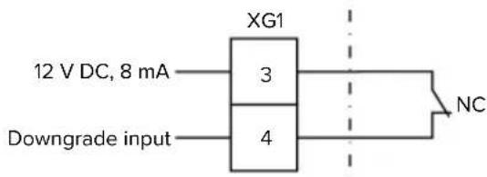
text_image
XG1 12 V DC, 8 mA 3 4 Downgrade input NCFig. 12: Schematic circuit diagram: Connection of an external switching contact
▶ Install external switching contact.
▶ Strip the cable.
▶ Strip the conductors 10 mm.
▶ Connect the conductors to terminals 3 and 4 (XG1).
▶ Comply with the connection data for the downgrade input.
“4 Technical data” [▶ 11]
Configuration
The reduced charging current, which is applied when the switching contact at the downgrade input is energised, can be set via DIP switches 4 and 5 on bank S2. The charging current is reduced on a percentage basis depending on the set maximum charging current.
| DIP switch setting (bank S2) | Percent-age of max. charging current | Reduced charging current (example: max. charging current = 10 A) | |
| 4 | 5 | ||
| OFF OFF 0 % 0 A | |||
| OFF ON 25 % 6 A * | |||
| ON OFF 50 % 6 A * | |||
| ON ON 75 % 7.5 A * | |||
* At least 6 A are always available for the charging process. If the calculated reduced charge current is less than 6 A, it is rounded up.
6.2.2 Blackout protection

The tasks described in this section may only be carried out by a qualified electrician.
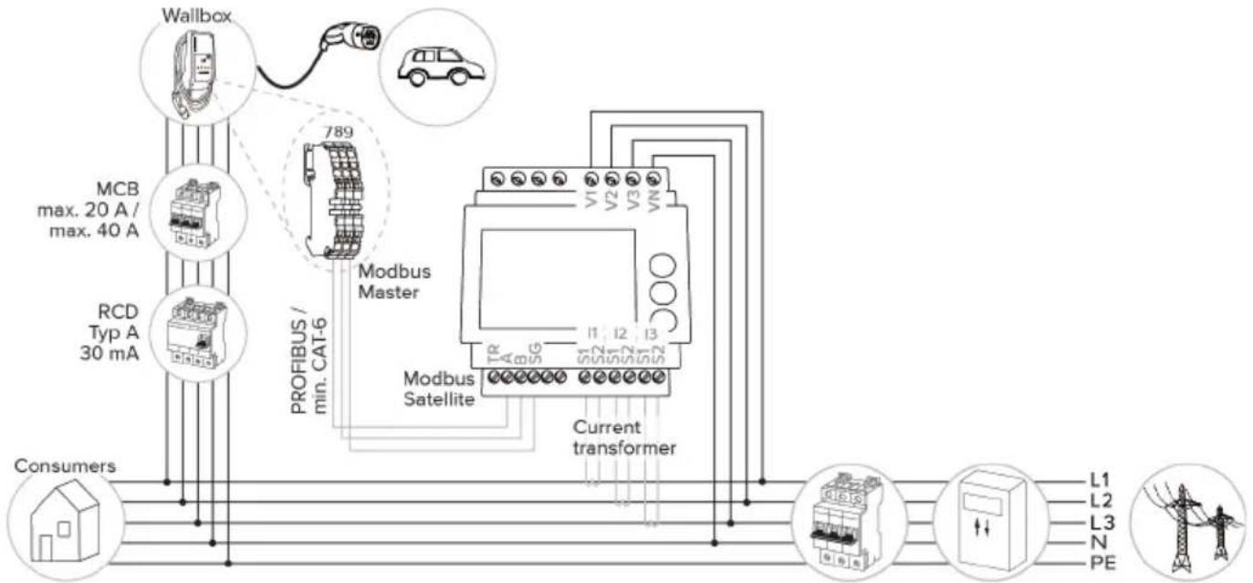
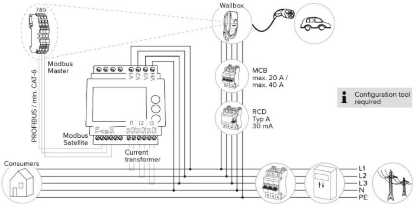
To prevent an overload at the building connection with a charging point (blackout protection), it is necessary to record the current values from the building connection with an additional external energy meter. The energy meter also takes account of other consumers in the building. Blackout protection is not possible in the case of building connections with more than 63 A.
6.2.2.1 Structure
The external energy meter can be placed in such a way that only the external consumers are measured or that the total consumption (external consumers and the charging station) is measured. The subsequent diagrams show the configuration structure for using the MENNEKES accessory set 18626 (Siemens PAC1600 7KT1661 incl. current transformer). The energy meter has to be connected in series in relation to the load, whenever using the TQ Energy Manager EM 420.
EN
Energy meter measures total consumption (standard setting)
flowchart
graph TD
    A["Wallbox"] -->|20A max. 40A| B["Modbus Master"]
    C["RCD Typ A 30 mA"] -->|min. CAT-6| B
    D["Consumers"] --> E["Current transformer"]
    B --> F["Modbus Satellite"]
    F --> G["L1 L2 L3 N PE"]
    style A fill:#f9f,stroke:#333
    style C fill:#f9f,stroke:#333
    style D fill:#f9f,stroke:#333
    style E fill:#f9f,stroke:#333
    style F fill:#ccf,stroke:#333
    style G fill:#cfc,stroke:#333
    style_H["Car"] --> I["789"]
    style I --> J["PROFIBUS / min. CAT-6"]
    style J --> K["Modbus Master"]
    style K --> L["Current transformer"]
    style_M["PC"] --> N["L1 L2 L3 N PE"]
Energy meter measures external consumers only
flowchart
graph TD
    A["789"] --> B["Modbus Master"]
    B --> C["Modbus Satellite"]
    C --> D["Current transformer"]
    D --> E["Wallbox"]
    E --> F["MCB max. 20 A / max. 40 A"]
    E --> G["RCD Typ A 30 mA"]
    H["Consumers"] --> I["L1 L2 L3 N PE"]
    style A fill:#f9f,stroke:#333
    style H fill:#ccf,stroke:#333
    style E fill:#cfc,stroke:#333
    style F fill:#fcc,stroke:#333
    style G fill:#cff,stroke:#333
    style I fill:#ffc,stroke:#333
    style_J["Configuration tool required"] --> K["L1 L2 L3 N PE"]
6.2.2.2 Connection and configuration
Connecting an external energy meter
The product is compatible with the following energy meters:
Siemens PAC1600 7KT1661 (The energy meter incl. the current transformer and instructions can be ordered from MENNEKES using part no. 18626.)
■ TQ Energy Manager EM 420
▶ Install the external energy meter in the upstream electrical installation.
▶ Connect the energy meter and the product with a data cable.
“5.7 Connecting the data line (Modbus RTU)” [▶ 17]
Configuration
To set up blackout protection, the following settings have to be made using DIP switches:
| DIP switch Required configuration | Brief description |
| 4, bank S1 ON Using Modbus RTU | |
| 5, bank S1 OFF Master | |
| 6, bank S1 Dependent on energy meter | ■ “OFF” = Siemens PAC1600 7KT1661■ “ON” = TQ Energy Manager EM 420 |
| 7, bank S1 OFF Solar charging deactivated | |
| 6, 7, 8; bank S2 | Dependent on building connectionMax. amperage - building connection |
The max. amperage provided by the building connection can be set to 16 A, 20 A, 25 A, 32 A, 35 A, 40 A, 50 A or 63 A.
| DIP switch setting (bank S2 at master charging point) | Max. am-perage [A] | ||
| 6 7 8 | |||
| OFF OFF OFF 63 | |||
| ON OFF OFF 50 | |||
| OFF ON OFF 40 | |||
| ON ON OFF 35 | |||
| OFF OFF ON 32 | |||
| ON OFF ON 25 | |||
| OFF ON ON 20 | |||
| ON ON ON 16 | |||
Configuration tool:
If the energy meter is to measure external consumers only, an additional setting has to be made in the configuration tool (“Meter measuring point” parameter).
“6.5.1 Description of the configuration tool”
[▶ 30]
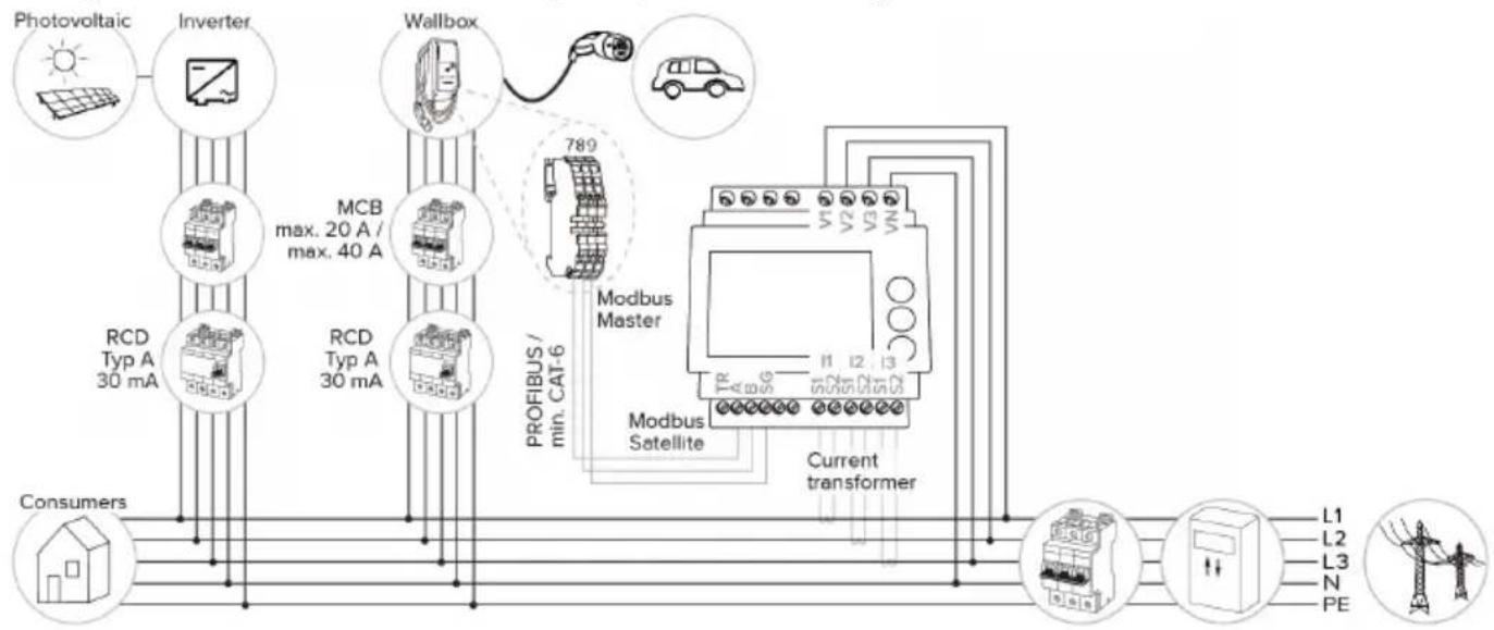
6.2.3 Solar charging

The tasks described in this section may only be carried out by a qualified electrician.
The product has 3 charging modes (Standard mode, Sunshine mode, Sunshine+ mode).
Standard mode
Charging occurs at maximum power. Mains power is used for charging unless there is a sufficient amount of excess energy.
Sunshine mode
The charging power is dependent on the excess energy from the photovoltaic system. Solar energy exclusively is used for charging. The charging process starts if there is a sufficient amount of energy available to charge the vehicle at 6 A per phase.
Sunshine+ mode
The charging power is dependent on the excess energy from the photovoltaic system. Regardless of how much current the photovoltaic system is feeding at the time, the vehicle is provided with minimum charging current at all times (if necessary through mains power). The minimum charging current (standard: 6 A per phase) can be adjusted using the configuration tool (a qualified electrician is required).
Special features of the 11 kW variant
The 11 kW variant supports single-phase and three-phase solar charging processes. Therefore, optimum use of both, underperforming and high-performing photovoltaic systems, is ensured. The charging station can also dynamically switch between single-phase and three-phase solar charging. The following settings can be made for the 11 kW variant (the configuration tool is required to change the setting):
■ Single-phase solar charging (standard setting): Single-phase charging occurs in Sunshine mode and Sunshine+ mode exclusively. Charging starts at 1.4 kW of excess energy and this can be raised to a max. of 3.7 kW.
■ Three-phase solar charging: Three-phase charging occurs in Sunshine mode and Sunshine+ mode exclusively. Charging starts at 4.2 kW of excess energy and this can be raised to a max. of 11 kW.
■ Dynamic switchover between single-phase and three-phase solar charging: Dynamic switchover between single-phase and three-phase charging occurs while charging in Sunshine mode or Sunshine+ mode. Charging starts at 1.4 kW of excess energy and this can be raised to a max. of 11 kW.
i
The automatic phase change has been implemented according to the procedure of CharlN. Compatibility with all vehicles on the market cannot be ensured by MENNEKES. In some cases, the charging process could be aborted or the vehicle or wallbox could sustain damage.
The Kia eNiro, Hyundai Kona or Renault Zoe, for example, could be incompatible. It is impossible to maintain a complete listing because compatibility can vary even within a series, depending on the year of manufacture and software version of a vehicle.
Please ask the vehicle manufacturer to clarify whether this function is supported as is by your vehicle.
MENNEKES shall not be held liable for any damage as a result of incorrect use or incompatibility.
Special features of the 22 kW variant
Solar charging starts at 4.2 kW of excess energy and this can be raised to a max. of 22 kW.
6.2.3.1 Structure
The external energy meter can be placed in such a way that only the external consumers are measured or that the total consumption (external consumers and the charging station) is measured. The subsequent diagrams show the configuration structure for using the MENNEKES accessory set 18626 (Siemens PAC1600 7KT1661 incl. current transformer). The energy meter has to be connected in series in relation to the load, whenever using the TQ Energy Manager EM 420.
Energy meter measures total consumption (standard setting)
flowchart
graph TD
    A["Photovoltaic"] --> B["Inverter"]
    B --> C["Wallbox"]
    C --> D["Modbus Master"]
    D --> E["Current transformer"]
    E --> F["Consumers"]
    subgraph Inputs
        G["Photovoltaic"] --> H["Inverter"]
        H --> I["Wallbox"]
        I --> J["Modbus Master"]
        J --> K["Current transformer"]
    end
    subgraph Outputs
        L1["L1"] --> M["Inductor"]
        L2["L2"] --> M
        L3["L3"] --> M
        N["N"] --> M
        PE["PE"] --> M
    end
    subgraph Outputs
        R1["RCD Typ A 30 mA"] --> S["Modbus Satellite"]
        T1["RCD Typ A 30 mA"] --> S
        U["PROFIBUS / min. CAT-6"] --> V["Modbus Master"]
    end
Energy meter measures external consumers only
flowchart
graph TD
    A["Photovoltaic"] --> B["Inverter"]
    B --> C["Modbus Master"]
    C --> D["Modbus Satellite"]
    D --> E["Current transformer"]
    E --> F["Wallbox"]
    F --> G["Car"]
    C --> H["PROFIBUS / min. CAT-6"]
    H --> I["Consumers"]
    style A fill:#f9f,stroke:#333
    style B fill:#ccf,stroke:#333
    style C fill:#cfc,stroke:#333
    style D fill:#fcc,stroke:#333
    style E fill:#cff,stroke:#333
    style F fill:#ffc,stroke:#333
    style G fill:#fcf,stroke:#333
    style H fill:#cff,stroke:#333
    style I fill:#ffc,stroke:#333
6.2.3.2 Connection and configuration
Connecting an external energy meter
The product is compatible with the following energy meters:
Siemens PAC1600 7KT1661 (The energy meter incl. the current transformer and instructions can be ordered from MENNEKES using part no. 18626.)
■ TQ Energy Manager EM 420
▶ Install the external energy meter in the upstream electrical installation.
▶ Connect the energy meter and the product with a data cable.
“5.7 Connecting the data line (Modbus RTU)” [▶ 17]
Configuration
For solar charging, the following settings have to be made using DIP switches:
| DIP switch (bank S1) | Required configuration | Brief description |
| 4 ON Using Modbus RTU | ||
| 5 OFF Master | ||
| 6 Dependent on energy meter | ■ “OFF” = Siemens PAC1600 7KT1661■ “ON” = TQ Energy Manager EM 420 | |
| 7 ON Solar charging activated | ||
Configuration tool:
If the energy meter is to measure external consumers only, an additional setting has to be made in the configuration tool ("Meter measuring point" parameter).
“6.5.1 Description of the configuration tool” [▶ 30]
Blackout protection:
Blackout protection is enabled automatically for solar charging, which is why the max. amperage provided by the building connection must also be set via the DIP switches.
“6.2.2 Blackout protection” [▶ 22]
Selecting the charging mode

text_image
Technical diagram of a device with labeled parts, including a control panel and spring mechanismFig. 13: Sun button
Press the Sun button (1) to select the charging mode according to the following diagram.
flowchart
graph LR
    A["Standard Mode"] --> B["Sunshine Mode"]
    B --> C["Sunshine+ Mode"]
    C --> A
Fig. 14: Switching the charging modes
The set charging mode is indicated by the "Sun" (2) LED:
| Status of “Sun” LED Set charging mode |
| Off (is not lit) Standard mode |
| Lights up Sunshine mode |
| Pulsates Sunshine+ mode |

■ The Sun button has no function unless solar charging has been set up.
The following information applies to both the 22 kW and 11 kW variants with enabled dynamic phase switchover:
■ Switching from Standard mode, Sunshine mode or Sunshine+ mode is always possible (also while charging is in progress).
■ The following information applies to the 11 kW variant with disabled dynamic phase switchover:
■ Switching from Standard mode, Sunshine mode or Sunshine+ mode is always possible (also while charging is in progress).
■ Switching between Standard mode and Sunshine(+) mode is not possible while charging is in progress. The vehicle must be disconnected from the charging station before switchover.
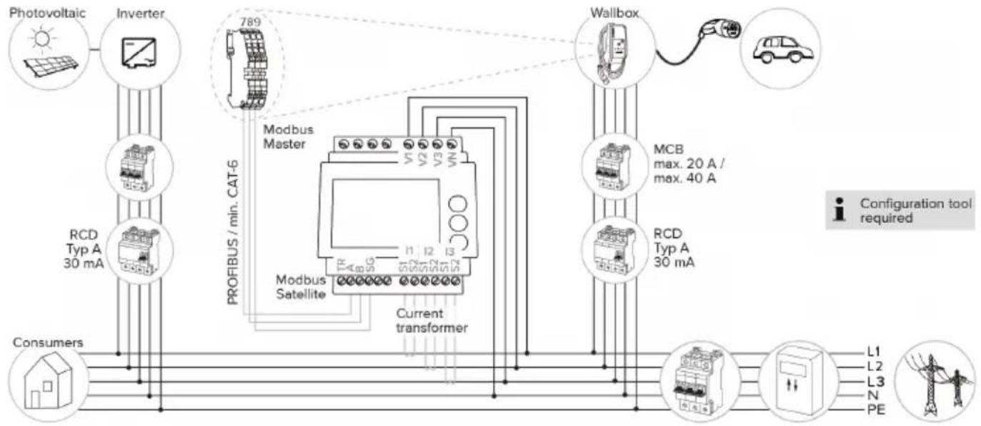
6.2.4 Energy management system

The tasks described in this section may only be carried out by a qualified electrician.
The product can be connected to an energy management system via Modbus RTU as needed to complete complex application cases. The product is controlled by the energy management system (master).

Information on compatible energy management systems and the description of the Modbus RTU interface (Modbus RTU Register Table) can be found on our website: https://www.chargeupyourday.com/service/compatible-systems-and-interfaces/
6.2.4.1 Structure
flowchart
graph TD
    A["Photovoltaic"] --> B["Inverter"]
    B --> C["Wallbox"]
    C --> D["Modbus Satellite"]
    D --> E["PROFIBUS / min. CAT-6"]
    E --> F["Modbus Master"]
    F --> G["EMS"]
    G --> H["LAN"]
    H --> I["Smartphone"]
    I --> J["Consumers"]
    B --> K["RCD Typ A 30 mA"]
    B --> L["RCD Typ A 30 mA"]
    C --> M["Max. 20 A / max. 40 A"]
    C --> N["789"]
    style A fill:#f9f,stroke:#333
    style J fill:#ccf,stroke:#333
    style I fill:#cfc,stroke:#333
    style K fill:#fcc,stroke:#333
    style L fill:#fcc,stroke:#333
    style M fill:#fcc,stroke:#333
    style N fill:#fcc,stroke:#333
    style O fill:#fff,stroke:#333
    style P fill:#fff,stroke:#333
    style Q fill:#fff,stroke:#333
    style R fill:#fff,stroke:#333
    style S fill:#fff,stroke:#333
    style T fill:#fff,stroke:#333
    style U fill:#fff,stroke:#333
    style V fill:#fff,stroke:#333
    style W fill:#fff,stroke:#333
    style X fill:#fff,stroke:#333
    style Y fill:#fff,stroke:#333
    style Z fill:#fff,stroke:#333
    style AA fill:#fff,stroke:#333
    style AB fill:#fff,stroke:#333
    style AC fill:#fff,stroke:#333
    style AD fill:#fff,stroke:#333
    style AE fill:#fff,stroke:#333
    style AF fill:#fff,stroke:#333
    style AG fill:#fff,stroke:#333
    style AH fill:#fff,stroke:#333
    style AI fill:#fff,stroke:#333
    style AJ fill:#fff,stroke:#333
    style AK fill:#fff,stroke:#333
    style AL fill:#fff,stroke:#333
    style AM fill:#fff,stroke:#333
    style AN fill:#fff,stroke:#333
    style AO fill:#fff,stroke:#333
    style AP fill:#fff,stroke:#333
    style AQ fill:#fff,stroke:#333
    style AR fill:#fff,stroke:#333
    style AS fill:#fff,stroke:#333
    style AT fill:#fff,stroke:#333
    style AU fill:#fff,stroke:#333
    style AV fill:#fff,stroke:#333
EN
6.2.4.2 Connection and configuration
Connecting the energy management system
▶ Install the energy management system in the upstream electrical installation.
▶ Connect the energy management system and the product with a data cable.
“5.7 Connecting the data line (Modbus RTU)” [▶ 17]
Configuration
To set up an energy management system via Modbus RTU, the following settings have to be made using DIP switches:
| DIP switch (bank S1) | Setting Brief description |
| 4 ON Using Modbus RTU | |
| 5 ON Satellite | |
6.3 Switching on the product

The tasks described in this section may only be carried out by a qualified electrician.
Requirement(s):
√ Product is installed correctly.
√ Product is not damaged.
√ The necessary protective devices are installed in the upstream electrical installation in compliance with the relevant national regulations.
“5.2.2 Protective devices” [▶ 14]
√ During the initial setting-up process, the product was inspected in accordance with IEC 60364-6 and the applicable national regulations (e.g. in Germany: DIN VDE 0100-600).
“6.4 Testing the product” [▶ 30]
▶ Switch on the power supply and check.
6.4 Testing the product

The tasks described in this section may only be carried out by a qualified electrician.
At initial start-up, test the product in accordance with IEC 60364-6 and the applicable national regulations (e.g. in Germany: DIN VDE 0100-600).
The test can be carried out in conjunction with the MENNEKES test box and standard-compliant test equipment. The MENNEKES test box simulates vehicle communication. Test boxes are available as an accessory from MENNEKES.
6.5 More settings
6.5.1 Description of the configuration tool
The basic settings can be made via DIP switches at the charging station. The configuration tool is required for advanced settings.
The following advanced settings can be made:
■ Perform firmware update
■ Change the default setting (20 A) for the unbalanced load limitation (possible values: 10 A ... 30 A)
■ Deactivate acoustic feedback
■ Deactivate Sleep mode (for reduced standby consumption of approx. 1 W)
■ Indicate the number and phase sequence of the connected phases
■ Activate undervoltage / overvoltage detection for the connected phases and set the respective limit values
■ Import and export settings
■ Only with AMTRON® Compact 2.0s 11: Set the number of phases for solar charging (single-phase (standard), three-phase, dynamic phase switchover)
■ Specify the energy meter measuring point for blackout protection and solar charging (standard: energy meter measures external consumers and charging station (total consumption))
■ Change the minimum solar charging current in Sunshine+ mode (standard: 6 A)
■ Manage RFID cards
■ Deactivate the wake-up function ("waking up" of vehicle so that a charging process can be continued)
In addition, the current operating values are displayed and the DIP switch settings are explained in the configuration tool. Should a fault occur, the configuration tool offers assistance with troubleshooting (fault message, log file).
i
To use the configuration tool, the MEN-NEKES configuration lead is required. You can find the MENNEKES configuration lead (order number 18625) on our website under "Products" > "Accessories". You can also download the configuration tool and instruction manual there.
The instruction manual for the configuration tool describes how to install and use the tool.
Comply with the configuration tool manual.
EN
Structure
7 Buttons to save and discard the changed settings and to reset to the factory settings
6.5.2 Managing RFID cards
√ Requirement: No charging process is in progress.
Adding or removing RFID card(s) to/from the whitelist
The master RFID card can be used to add new RFID cards to the internal whitelist or to remove them from it.
▶ Hold the RFID card in front of the RFID card reader to activate Teach mode.
→ The "Sun" LED flashes.
▶ Hold RFID cards in front of the RFID card reader.
If the RFID card has not yet been included in the whitelist, it will be added to the whitelist, and the “Standby” LED flashes once.
If the RFID card has already been included in the whitelist, it will be removed from the whitelist, and the "Fault" LED flashes once.
If 10 RFID cards have already been included in the whitelist, the whitelist is filled to capacity, and the “Fault” LED flashes three times.

■ Teach mode will end after 60 second and the “Sun” LED goes back to indicate the set status.
■ The master RFID card cannot be used to authorise charging processes.
Programming a master RFID card

The DIP switches 1, 2 and 3 on bank S2 are mainly needed to set the maximum charging current.
Exception: If all three DIP switches are set to "ON", a new master RFID card can be programmed. The product indicates the operating state "Fault".
▶ Disconnect the product from voltage.
▶ Set DIP switches 1, 2 and 3 on bank S2 to "ON".
▶ Switch on the product.
▶ Hold the new master RFID card in front of the RFID card reader.
▶ Disconnect the product from voltage.
▶ Set the desired maximum charging current via DIP switches 1, 2 and 3 on bank S2.
▶ Switch on the product.
Deleting all programmed RFID card from the whitelist
▶ Hold the master RFID card in front of the RFID card reader for 10 seconds.
All programmed RFID cards will be deleted from the whitelist, and the “Fault” LED flashes once.
→ The master RFID card will not be deleted.
Using the configuration tool to manage the internal whitelist
Alternatively, the configuration tool can be used to manage the internal whitelist.

"6.5.1 Description of the configuration tool"
[▶ 30]
6.6 Closing the product

The tasks described in this section may only be carried out by a qualified electrician.

ATTENTION
Material damage due to crushed components or cables
Damage and malfunctions can occur due to crushed components or cables.
When closing the product ensure that components or cables are not crushed.
▶ Fix components or cables in place if necessary.
text_image
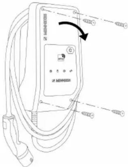
MERRHOS MERRHOSFig. 16: Closing the product
▶ Fold the top section of the housing upward.
▶ Screw the top and bottom housing sections together. Tightening torque: 1.2 Nm.
7 Operation
7.1 Authorisation
▶ Authorise (dependent on the configuration).
The following authorisation options are available:
No authorisation (Autostart)
All users can charge.
Authorisation through RFID
Users whose RFID card has been entered in the whitelist can charge.
▶ Hold the RFID card in front of the RFID card reader.

If charging does not start within 5 minutes, the authorisation is reset and the product switches to Standby mode. The authorisation process must be repeated.
7.2 Charging the vehicle

WARNING
Risk of injury from using unsuitable aids
If unsuitable aids (e.g. adapter plugs, extension cables) are used during the charging process, there is a risk of electric shock or cable fire.
▶ Use only the charging cable intended for the vehicle and the product.
Requirement(s):
√ The authorisation process is complete (if necessary).
√ The vehicle and the charging cable are suitable for Mode 3 charging.
▶ Unroll the charging cable completely.
▶ Connect the charging cable to the vehicle.
Selecting the charging mode

"3.5 Solar charging modes" [▶ 8]
text_image
Technical diagram of a device with labeled parts, showing front panel and side view with spring and button indicatorsEN
Fig. 17: Sun button
Press the Sun button (1) to select the charging mode according to the following diagram.
flowchart
graph LR
    A["Standard Mode"] --> B["Sunshine Mode"]
    B --> C["Sunshine+ Mode"]
    C --> D["Return to Standard"]
Fig. 18: Switching the charging modes
The set charging mode is indicated by the "Sun" (2) LED:
Status of "Sun" LED Set charging mode
Off (is not lit) Standard mode
Lights up Sunshine mode
Pulsates Sunshine+ mode
i
■ The Sun button has no function unless solar charging has been set up.
The following information applies to both the 22 kW and 11 kW variants with enabled dynamic phase switchover:
■ Switching from Standard mode, Sunshine mode or Sunshine+ mode is always possible (also while charging is in progress).
■ The following information applies to the 11 kW variant with disabled dynamic phase switchover:
■ Switching from Standard mode, Sunshine mode or Sunshine+ mode is always possible (also while charging is in progress).
■ Switching between Standard mode and Sunshine(+) mode is not possible while charging is in progress. The vehicle must be disconnected from the charging station before switchover.
Charging process does not start
If the charging process does not start, the communication between the charging point and the vehicle may be faulty, for example.
▶ Check the charging plug and the charging socket for foreign objects and remove if necessary.
▶ Have the charging cable replaced by a qualified electrician if necessary.
Ending the charging process

ATTENTION
Material damage due to tensile stress
Tensile stress on the cable may cause cable breaks and other damage.
▶ Pull the charging plug out of the charging socket.
▶ End the charging process on the vehicle or by holding the RFID card in front of the RFID card reader.
▶ Pull the charging plug out of the charging socket.
▶ Put the protective cap on the charging plug.
▶ Hang the charging cable kink-free.
8 Servicing
8.1 Maintenance

DANGER
Risk of electric shock due to damaged product
If a damaged product is used people can be seriously injured or killed due to an electric shock.
▶ Do not use a damaged product.
▶ Mark a damaged product to ensure that no one uses it.
▶ Arrange for a qualified electrician to rectify the damage without delay.
▶ Have the product taken out of service by a qualified electrician if necessary.
▶ Check the product for operational readiness and external damage daily or on each charging process.
Examples of damage:
■ Defective housing
■ Defective or missing components
■ Illegible or missing safety labels

A maintenance contract with a responsible service partner guarantees regular maintenance.
Maintenance intervals

The tasks described below may only be carried out by a qualified electrician.
Select the maintenance intervals with due consideration of the following aspects:
■ Age and condition of the product
■ Environmental influences
■ Mechanical stress
■ Last test reports
Perform maintenance at least in the following intervals.
Every 6 months:
| Component | Maintenance work |
| Housing exterior | ▶ Visually inspect for defects and damage.▶ Check product for cleanliness and clean if necessary. |
| Housing interior | ▶ Check product for foreign objects and remove if necessary.▶ Visually inspect for dryness, remove any foreign objects from the seal and allow the product to dry. Carry out a function test if necessary.▶ Check the fastening on the wall or on the MENNEKES stand system (e.g. pole) and tighten the screws if necessary. |
| Protective devices | ▶ Visually inspect for damage. |
| LED information panel | ▶ Check LED info panel for function and readability. |
| Charging cable | ▶ Check the charging cable for damage (e.g. kinks, cracks).▶ Check the charging cable for cleanliness and foreign objects, clean and remove foreign objects if necessary. |
Annually:
| Component Maintenance work | |
| Terminals | ▶ Check terminals of the supply line and retighten if necessary. |
Component Maintenance work
Electrical system
▶ Inspection of the electrical system in accordance with IEC 60364-6 and the respective applicable national regulations (e.g. DIN VDE 0105-100 in Germany).
▶ Repetition of measurements and tests according to IEC 60364-6 and the applicable national regulations (e.g. in Germany: DIN VDE 0105-100).
Carry out a functional test and charging simulation (e.g. using a MENNEKES test box and standard-compliant test equipment).
▶ Properly eliminate damage to the product.
▶ Document maintenance.
You can find the MENNEKES maintenance log on our website under "Service" > "Brochures and infomaterial" > "Documents for installers".
8.2 Cleaning

DANGER
Risk of electric shock due to improper cleaning
The product contains electrical components that carry high voltage. In case of improper cleaning, people can be seriously injured or killed due to electric shock.
▶ Clean only the outside of the housing.
▶ Do not use running water.

ATTENTION
Material damage due to improper cleaning
Improper cleaning can damage the housing.
▶ Wipe the housing with a dry cloth or a cloth lightly moistened with water or spirit (94 % vol.).
▶ Do not use running water.
▶ Do not use high-pressure cleaning devices.
8.3 Firmware update

You can download the current firmware from our website under "Service".
The configuration tool is required to perform a firmware update.
“6.5.1 Description of the configuration tool” [▶ 30]
9 Troubleshooting
If a fault occurs, the "Fault" symbol lights up or flashes on the LED information panel. The fault must be rectified for further operation.
"Fault" symbol flashes
If the "Fault" symbol flashes, the fault can be rectified by the user or operator. Possible faults are, for example:
■ Fault during the charging process
■ Operating temperature too high
■ Undervoltage or overvoltage is present
To correct the fault, observe the following sequence:
▶ End the charging process and unplug the charging cable.
If necessary, wait until the product has cooled or under / overvoltage is no longer present.
Plug the charging cable back in and start the charging process.

If the fault could not be corrected, contact your responsible service partner.
“1.1 Contact” [▶ 2]
"Fault" symbol lights up
If the "Fault" symbol lights up, the fault can only be rectified by a qualified electrician.

The tasks described below may only be carried out by a qualified electrician.
Possible faults are, for example:
■ Self-test of the electronics failed
■ Self-test of the DC residual current monitoring failed
■ Welded load contact (welding detection)

The configuration tool is required to view a diagnosis of the fault and download log files.
☐ "6.5.1 Description of the configuration tool" [▶ 30]
To correct the fault, observe the following sequence:
▶ Disconnect the product from the power supply for 3 minutes and restart.
▶ Check whether a firmware update is available (on our website under "Service") and upload it via the configuration tool if necessary.
Read out the fault diagnosis in the configuration tool and rectify the fault.

You can find a document on troubleshooting on our website under "Service" > "Brochures" > "Documents for installers". The fault messages, possible causes and possible solutions are described there.
▶ Document the fault
You can find the MENNEKES fault log on our website under "Service" > "Brochures" > "Documents for installers".
9.1 Spare parts
If replacement parts are necessary for troubleshooting, these must first be checked to ensure identical design.
▶ Use only original spare parts that are provided and / or approved by MENNEKES.
See the installation manual for the spare part
10 Taking out of service

The tasks described in this section may only be carried out by a qualified electrician.
▶ Disconnect the supply line and secure against reactivation.
▶ Open the product.
“5.4 Opening the product” [▶ 15]
▶ Disconnect the supply line and the control / data line (if applicable).
▶ Unfasten the product from the wall or from the stand system provided by MENNEKES (e.g. pole).
▶ Run the supply line and the control / data line (if applicable) out of the housing.
▶ Close the product.
“6.6 Closing the product” [▶ 32]
10.1 Storage
Proper storage can positively affect and maintain the operability of the product.
▶ Clean the product before storing.
▶ Store the product in a clean and dry place in its original or other suitable packaging.
▶ Observe permissible storage conditions.
| Permissible storage conditions | ||
| Min. Max. | ||
| Storage temperature [°C] -30 +50 | ||
| Average temperature over 24 hours [°C] | +35 | |
| Altitude [m above sea level] 2,000 | ||
| Relative humidity (non-condensing) [%] | 95 | |
10.2 Disposal
▶ Comply with the statutory regulations and provisions for disposal and environmental protection in the country of use.
▶ Dispose of packaging sorted by type.

The product must not be discarded with household waste.
Recycling options for private households
The product can be returned free of charge at the collection points operated by the public waste management authorities or at the disposal points established in accordance with Directive 2012/19/EU.
Recycling options for businesses
Details regarding commercial disposal are available from MENNEKES on request.
“1.1 Contact” [▶ 2]
Personal data / data protection
Personal data may be stored on the product. The end user is personally responsible for deleting the data.
Índice
Sitio web: https://www.chargeupyourday.com/

Centro de servicio
text_image
Technical diagram of an electronic device with numbered components for identificationFig. 4: Vista interior
text_image
Technical diagram of an electric vehicle charging station with labeled components and wiring connectionsAMTRON® Compact 2.0s 22
AMTRON® Compact 2.0s 11
text_image
Technical diagram of a mechanical assembly with labeled components and an arrow pointing to a specific part.text_image
XG1 12 V CC, 8 mA 3 4 Entrada Downgrade NCtext_image
Technical diagram of a device with labeled parts, showing internal components and connection pointsFig. 13: Pulsador de sol
text_image
Diagram of a device with labeled parts, showing front panel and internal componentsES
Fig. 17: Pulsador de sol
Site web : https://www.chargeupyourday.com/

Partenaires S.A.V.
text_image
Diagram of an electric vehicle charging station with numbered components and labeled connectorstext_image
Technical diagram of an electronic device with numbered components for identificationtext_image
MINH038 MINH038 MINH038text_image
L1L2L3N PEAMTRON® Compact 2.0s 22
AMTRON® Compact 2.0s 11
text_image
Technical diagram showing a mechanical or architectural component with labeled parts and an arrow pointing to a specific section.text_image
Technical diagram of a device with labeled parts, showing internal components and connection pointstext_image
Technical diagram of a device with labeled parts, showing front panel and base with spring baseFR
Home page: https://www.chargeupyourday.com/

text_image
Technical diagram of an electronic device with numbered components for identificationFig. 4: Vista interna
1 Passacavi *
2 Tasto Solare
3 Morsetti
text_image
Technical diagram of an electric vehicle charging station with labeled components and wiring connectionstext_image
L1L2L3N PEAMTRON® Compact 2.0s 22
AMTRON® Compact 2.0s 11
text_image
Technical diagram of a mechanical or electrical component with labeled parts and an arrow pointing to a specific section.text_image
XG1 12 V DC, 8 mA 3 4 Ingresso Downgrade NCtext_image
Technical diagram of a device with labeled parts, showing internal components and connection pointsFig. 13: Tasto Sole
text_image
MEMSOS MEMSOS MEMSOStext_image
Technical diagram of a device with labeled components, including a control panel and spring base.Fig. 17: Tasto Sole
8.3 Update firmware....38
9 Storingsoplossing.... 39
9.1 Reserveonderdelen....39
10 Buitendienststelling 40
10.1 Opslag....40
Homepage: https://www.chargeupyourday.com/

Servicepartner
text_image
Technical diagram of an electronic device with numbered components for identificationAMTRON® Compact 2.0s 22
AMTRON® Compact 2.0s 11
| Instelling dipschakelaar (bank S2) Max. laad- | ||
| 1 2 3 | stroom [A] | |
| OFF OFF OFF 16 | ||
| ON OFF OFF 16 | ||
| Instelling dipschakelaar (bank S2) Max. laad-stroom [A] | ||
| 1 2 3 | ||
| OFF ON OFF 16 | ||
| ON ON OFF 16 | ||
| OFF OFF ON 13 | ||
| ON OFF ON 10 | ||
| OFF ON ON 6 | ||
text_image
Technical diagram of a mechanical assembly with labeled components and an arrow pointing to a specific part.text_image
Technical diagram of a handheld device with labeled parts, showing front panel and internal componentstext_image
Technical diagram of a device with labeled parts, showing front panel and side view with spring and button indicatorsSymbool "Storing" brandt
"5.4 Product openen" [▶ 15]
Hemsida: https://www.chargeupyourday.com/

Servicepartner
text_image
Diagram of an electric vehicle charging station with numbered components and labeled portsFig. 3: Utsidan
text_image
Labeled diagram of a handheld device showing internal components and parts with numbered annotationsFig. 4: Vy inifrån
AMTRON® Compact 2.0s 22
AMTRON® Compact 2.0s 11
text_image
Technical diagram showing a mechanical assembly with labeled components and an arrow pointing to a specific part."6.2.2 Blackoutskydd" [▶ 21]
Välj laddningsläge
text_image
Technical diagram of a device with labeled parts, showing internal components and connection pointsFig. 13: Solknapp
8.3 Firmware Update....35
9 Feilretting.... 36
9.1 Reservedeler ....36
Nettsted: https://www.chargeupyourday.com/

Servicepartner
Hvis du har spørsmål angående produktet, ber vi deg ta kontakt med din servicepartner. På vår hjemmeside under «Partnersuche» finner du kontaktinformasjon for din region.
MENNEKES
text_image
Diagram of an electric vehicle charging station with numbered components and labeled portstext_image
Technical diagram of an open mobile phone case with numbered components for identificationtext_image
Technical diagram of an EV charging station with labeled components and directional arrows indicating cable routing or signal flow.text_image
L1L2L3N PENO
AMTRON® Compact 2.0s 22
| Innstilling DIP-brytere (bank S2) Maks. | ladestrøm [A] | ||
| 1 2 3 | |||
| OFF OFF OFF 32 | |||
| ON OFF OFF 25 | |||
| OFF ON OFF 20 | |||
| ON ON OFF 16 | |||
| OFF OFF ON 13 | |||
| ON OFF ON 10 | |||
| OFF ON ON 6 | |||
AMTRON® Compact 2.0s 11
| Innstilling DIP-brytere (bank S2) Maks. | ladestrøm [A] | ||
| 1 2 3 | |||
| OFF OFF OFF 16 | |||
| ON OFF OFF 16 | |||
| OFF ON OFF 16 | |||
| ON ON OFF 16 | |||
| OFF OFF ON 13 | |||
| ON OFF ON 10 | |||
| OFF ON ON 6 | |||
natural_image
Technical line drawing of a mechanical assembly with no visible text or symbolsFig. 11: Ta ut jumperen
Ta ut jumperen.

text_image
XG1 12 V DC, 8 mA 3 4 Downgrade-inngang NCFig. 12: Prinsipielt koblingskjema: tilkobling av en ekstern bryterkontakt
text_image
Technical diagram of a device with labeled parts, showing internal components and connection pointsFig. 13: Solknapp
text_image
MENKORS G WNT MENKORS Gtext_image
Technical diagram of a device with labeled parts, showing internal components and connection pointsFig. 17: Solknapp
Honlap: https://www.chargeupyourday.com/

Szervizpartner
text_image
Technical diagram of a handheld device with numbered components for identification- ábra: Belső nézet
text_image
MEMSHEV MEMSHEV MEMSHEVtext_image
L1L2L3NPE5 Master / satellite
AMTRON® Compact 2.0s 22
AMTRON® Compact 2.0s 11
natural_image
Diagram of a mechanical or architectural component with numbered parts and an arrow pointing to a specific area (no text or symbols present)text_image
Diagram of a device with labeled parts, showing front panel and internal components- ábra: Nap gomb
text_image
MEANEROS MEMSOS © MEMSOStext_image
Diagram of a device with labeled parts, showing front panel and internal components- ábra: Nap gomb
Spletna stran: https://www.chargeupyourday.com/

Servisni partner
text_image
Technical diagram of an electronic device with numbered components for identificationsl. 4: Prikaz notranjosti
1 Kabelske uvodnice *
2 Solarna tipka
3 Sponke
text_image
Technical diagram of an electric vehicle charging station with labeled components and wiring connectionssl. 5: Odpiranje izdelka
V stanju pri dobavi zgornji del ohišja ni privit. Vijaki so del obsega dobave.
▶ Vijake po potrebi odvijte.
Zgornji del ohišja preklopite navzdol.
5.5 Montaža izdelka na steno

POMEMBNO
text_image
L1L2L3NPEAMTRON® Compact 2.0s 22
Maks. napajalni tok je mogoče nastaviti na 6 A, 10 A, 13 A, 16 A, 20 A, 25 A ali 32 A.
| Nastavitev DIP-stikala (enota S2) Maks. | ||
| 1 2 3 | polnilni tok [A] | |
| OFF OFF OFF 32 | ||
| ON OFF OFF 25 | ||
| OFF ON OFF 20 | ||
| ON ON OFF 16 | ||
| OFF OFF ON 13 | ||
| ON OFF ON 10 | ||
| OFF ON ON 6 | ||
AMTRON® Compact 2.0s 11
Maks. napajalni tok je mogoče nastaviti na 6 A, 10 A, 13 A ali 16 A.
| Nastavitev DIP-stikala (enota S2) Maks. | ||
| 1 2 3 | polnilni tok [A] | |
| OFF OFF OFF 16 | ||
| ON OFF OFF 16 | ||
| OFF ON OFF 16 | ||
| ON ON OFF 16 | ||
| OFF OFF ON 13 | ||
| ON OFF ON 10 | ||
| OFF ON ON 6 | ||
text_image
Technical diagram of a mechanical assembly with labeled components and an arrow indicating a specific part.sl. 11: Odstranitev mostička
text_image
Technical diagram of a device with labeled parts, showing front panel and spring connectionsl. 13: Tipka za sonce
text_image
Technical diagram of a device with labeled parts, showing front panel and internal componentssl. 17: Tipka za sonce
www.chargeupyourday.com