
C 18DSL - Saw HITACHI - Free user manual and instructions
Find the device manual for free C 18DSL HITACHI in PDF.
| Brand | Hitachi (HiKOKI) |
| Model | C 18DSL |
| Product type | Cordless circular saw |
| Nominal voltage | 18 V |
| No-load speed | 3400 min⁻¹ |
| Cutting depth at 90° | 57 mm |
| Cutting depth at 45° | 40 mm |
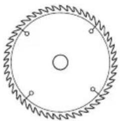
| Compatible blade diameter | 165 mm to 150 mm |
| Light bulb | 12 V, 5 W |
| Weight (with battery) | 3.1 – 3.7 kg depending on battery |
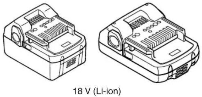
| Battery type | Lithium-ion (Li-ion) |
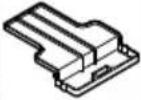
| Compatible charger | UC18YFSL or UC18YML2 |
| Recommended charging temperature | 0 °C – 40 °C (ideal 20–25 °C) |
| Electric brake | Yes, quick blade stop |
| Lower guard | Automatic and manual retraction |
| Sound power level | 103 dB(A) |
| Sound pressure level | 92 dB(A) |
| Vibration (cutting gray cardboard) | 2.0 m/s² (uncertainty K=1.5 m/s²) |
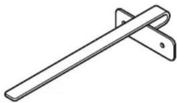
| Standard accessories | Saw blade, wrench, guide, charger, battery (depending on version) |
| Applications | Cutting wood and panels |
| Maintenance | Regular cleaning of ventilation slots and lower guard |
| Repairability | Spare parts available from HiKOKI authorized service center |
Frequently Asked Questions - C 18DSL HITACHI
User questions about C 18DSL HITACHI
0 question about this device. Answer the ones you know or ask your own.
Ask a new question about this device
Download the instructions for your Saw in PDF format for free! Find your manual C 18DSL - HITACHI and take your electronic device back in hand. On this page are published all the documents necessary for the use of your device. C 18DSL by HITACHI.
USER MANUAL C 18DSL HITACHI
natural_image
Technical line drawing of a mechanical assembly with no visible text or symbols
en Handling instructions
de Bedienungsanleitung
fr Mode d'emploi
it Istruzioni per l'uso
nl Gebruiksaanwijzing
es Instrucciones de manejo
pt Instruções de uso
sv Bruksanvisning
da Brugsanvisning
no Bruksanvisning
fi Käyttöohjeet
el Οδηγίες χειρισμού
pl Instrukcja obsługi
hu Kezelési utasítás
cs Návod k obsluze
tr Kullanım talimatları
ro Instructiuni de utilizare
① Navodila za rokovanje
sk Pokyny na manipuláciu
bg Инструкция за експлоатация
sr Uputstvo za rukovanje
hr Upute za rukovanje
(Original instructions)
GENERAL POWER TOOL SAFETY WARNINGS

WARNING
Read all safety warnings, instructions, illustrations and specifications provided with this power tool.
Failure to follow all instructions listed below may result in electric shock, fire and/or serious injury.
Save all warnings and instructions for future reference.
The term “power tool” in the warnings refers to your mains-operated (corded) power tool or battery-operated (cordless) power tool.
1) Work area safety
a) Keep work area clean and well lit.
Cluttered or dark areas invite accidents.
b) Do not operate power tools in explosive atmospheres, such as in the presence of fl ammable liquids, gases or dust.
Power tools create sparks which may ignite the dust or fumes.
c) Keep children and bystanders away while operating a power tool.
Distractions can cause you to lose control.
2) Electrical safety
a) Power tool plugs must match the outlet. Never modify the plug in any way. Do not use any adapter plugs with earthed (grounded) power tools.
Unmodified plugs and matching outlets will reduce risk of electric shock.
b) Avoid body contact with earthed or grounded surfaces, such as pipes, radiators, ranges and refrigerators.
There is an increased risk of electric shock if your body is earthed or grounded.
c) Do not expose power tools to rain or wet conditions.
Water entering a power tool will increase the risk of electric shock.
d) Do not abuse the cord. Never use the cord for carrying, pulling or unplugging the power tool.
Keep cord away from heat, oil, sharp edges or moving parts.
Damaged or entangled cords increase the risk of electric shock.
e) When operating a power tool outdoors, use an extension cord suitable for outdoor use.
Use of a cord suitable for outdoor use reduces the risk of electric shock.
f) If operating a power tool in a damp location is unavoidable, use a residual current device (RCD) protected supply.
Use of an RCD reduces the risk of electric shock.
3) Personal safety
a) Stay alert, watch what you are doing and use common sense when operating a power tool.
Do not use a power tool while you are tired or under the influence of drugs, alcohol or medication.
A moment of inattention while operating power tools may result in serious personal injury.
b) Use personal protective equipment. Always wear eye protection.
Protective equipment such as a dust mask, non-skid safety shoes, hard hat or hearing protection used for appropriate conditions will reduce personal injuries.
c) Prevent unintentional starting. Ensure the switch is in the off -position before connecting to power source and/or battery pack, picking up or carrying the tool.
Carrying power tools with your fi nger on the switch or energising power tools that have the switch on invites accidents.
d) Remove any adjusting key or wrench before turning the power tool on.
A wrench or a key left attached to a rotating part of the power tool may result in personal injury.
e) Do not overreach. Keep proper footing and balance at all times.
This enables better control of the power tool in unexpected situations.
f) Dress properly. Do not wear loose clothing or jewellery. Keep your hair and clothing away from moving parts.
Loose clothes, jewellery or long hair can be caught in moving parts.
g) If devices are provided for the connection of dust extraction and collection facilities, ensure these are connected and properly used.
Use of dust collection can reduce dust-related hazards.
h) Do not let familiarity gained from frequent use of tools allow you to become complacent and ignore tool safety principles.
A careless action can cause severe injury within a fraction of a second.
4) Power tool use and care
a) Do not force the power tool. Use the correct power tool for your application.
The correct power tool will do the job better and safer at the rate for which it was designed.
b) Do not use the power tool if the switch does not turn it on and off.
Any power tool that cannot be controlled with the switch is dangerous and must be repaired.
c) Disconnect the plug from the power source and/or remove the battery pack, if detachable, from the power tool before making any adjustments, changing accessories, or storing power tools.
Such preventive safety measures reduce the risk of starting the power tool accidentally.
d) Store idle power tools out of the reach of children and do not allow persons unfamiliar with the power tool or these instructions to operate the power tool.
Power tools are dangerous in the hands of untrained users.
e) Maintain power tools and accessories. Check for misalignment or binding of moving parts, breakage of parts and any other condition that may affect the power tool's operation. If damaged, have the power tool repaired before use.
Many accidents are caused by poorly maintained power tools.
f) Keep cutting tools sharp and clean.
Properly maintained cutting tools with sharp cutting edges are less likely to bind and are easier to control.
g) Use the power tool, accessories and tool bits etc. in accordance with these instructions, taking into account the working conditions and the work to be performed.
Use of the power tool for operations different from those intended could result in a hazardous situation.
h) Keep handles and grasping surfaces dry, clean and free from oil and grease.
Slippery handles and grasping surfaces do not allow for safe handling and control of the tool in unexpected situations.
5) Battery tool use and care
a) Recharge only with the charger specified by the manufacturer.
A charger that is suitable for one type of battery pack may create a risk of fire when used with another battery pack.
b) Use power tools only with specifically designated battery packs.
Use of any other battery packs may create a risk of injury and fire.
c) When battery pack is not in use, keep it away from other metal objects, like paper clips, coins, keys, nails, screws or other small metal objects, that can make a connection from one terminal to another.
Shorting the battery terminals together may cause burns or a fire.
d) Under abusive conditions, liquid may be ejected from the battery; avoid contact. If contact accidentally occurs, fl ush with water. If liquid contacts eyes, additionally seek medical help.
Liquid ejected from the battery may cause irritation or burns.
e) Do not use a battery pack or tool that is damaged or modified.
Damaged or modified batteries may exhibit unpredictable behaviour resulting in fire, explosion or risk of injury.
f) Do not expose a battery pack or tool to fire or excessive temperature.
Exposure to fire or temperature above 130^ C cause explosion.
g) Follow all charging instructions and do not charge the battery pack or tool outside the temperature range specified in the instructions.
Charging improperly or at temperatures outside the specified range may damage the battery and increase the risk of fi re.
6) Service
a) Have your power tool serviced by a qualified repair person using only identical replacement parts.
This will ensure that the safety of the power tool is maintained.
b) Never service damaged battery packs. Service of battery packs should only be performed by the manufacturer or authorized service providers.
PRECAUTION
Keep children and infi rm persons away.
When not in use, tools should be stored out of reach of children and infi rm persons.
CORDLESS CIRCULAR SAW SAFETY WARNINGS
Cutting procedures
a) ⚠️ DANGER: Keep hands away from cutting area and the blade. Keep your second hand on auxiliary handle, or motor housing.
If both hands are holding the saw, they cannot be cut by the blade.
b) Do not reach underneath the workpiece.
The guard cannot protect you from the blade below the workpiece.
c) Adjust the cutting depth to the thickness of the workpiece.
Less than a full tooth of the blade teeth should be visible below the workpiece.
d) Never hold the workpiece in your hands or across your leg while cutting. Secure the workpiece to a stable platform.
It is important to support the work properly to minimize body exposure, blade binding, or loss of control.
e) Hold the power tool by insulated gripping surfaces, when performing an operation where the cutting tool may contact hidden wiring or its own cord.
Contact with a “live” wire will also make exposed metal parts of the power tool “live” and could give the operator an electric shock.
f) When ripping, always use a rip fence or straight edge guide.
This improves the accuracy of cut and reduces the chance of blade binding.
g) Always use blades with correct size and shape (diamond versus round) of arbour holes.
Blades that do not match the mounting hardware of the saw will run off -centre, causing loss of control.
h) Never use damaged or incorrect blade washers or bolt.
The blade washers and bolt were specially designed for your saw, for optimum performance and safety of operation.
Kickback causes and related warnings
- kickback is a sudden reaction to a pinched, jammed or misaligned saw blade, causing an uncontrolled saw to lift up and out of the workpiece toward the operator;
- when the blade is pinched or jammed tightly by the kerf mayclosing down, the blade stalls and the motor reaction drives the unit rapidly back toward the operator;
- if the blade becomes twisted or misaligned in the cut, the teeth at the back edge of the blade can dig into the top surface of the wood causing the blade to climb out of the kerf and jump back toward the operator.
Kickback is the result of saw misuse and/or incorrect operating procedures or conditions and can be avoided by taking proper precautions as given below.
a) Maintain a firm grip with both hands on the saw and position your arms to resist kickback forces. Position your body to either side of the blade, but not in line with the blade.
Kickback could cause the saw to jump backwards, but kickback forces can be controlled by the operator, if proper precautions are taken.
b) When blade is binding, or when interrupting a cut for any reason, release the trigger and hold the saw motionless in the material until the blade comes to a complete stop.
Never attempt to remove the saw from the work or pull the saw backward while the blade is in motion or kickback may occur.
Investigate and take corrective actions to eliminate the cause of blade binding.
c) When restarting a saw in the workpiece, centre the saw blade in the kerf so that the saw teeth are not engaged into the material.
If a saw blade binds, it may walk up or kickback from the workpiece as the saw is restarted.
d) Support large panels to minimise the risk of blade pinching and kickback.
Large panels tend to sag under their own weight. Supports must be placed under the panel on both sides, near the line of cut and near the edge of the panel.
e) Do not use dull or damaged blades.
Unsharpened or improperly set blades produce narrow kerf causing excessive friction, blade binding and kickback.
English
f) Blade depth and bevel adjusting locking levers must be tight and secure before making the cut.
If blade adjustment shifts while cutting, it may cause binding and kickback.
g) Use extra caution when sawing into existing walls or other blind areas.
The protruding blade may cut objects that can cause kickback.
Lower guard function
a) Check the lower guard for proper closing before each use. Do not operate the saw if the lower guard does not move freely and close instantly. Never clamp or tie the lower guard into the open position.
If the saw is accidentally dropped, the lower guard may be bent. Raise the lower guard with the retracting handle and make sure it moves freely and does not touch the blade or any other part, in all angles and depths of cut.
b) Check the operation of the lower guard spring. If the guard and the spring are not operating properly, they must be serviced before use.
Lower guard may operate sluggishly due to damaged parts, gummy deposits, or a build-up of debris.
c) The lower guard may be retracted manually only for special cuts such as "plunge cuts" and "compound cuts". Raise the lower guard by the retracting handle and as soon as the blade enters the material, the lower guard must be released.
For all other sawing, the lower guard should operate automatically.
d) Always observe that the lower guard is covering the blade before placing the saw down on bench or floor.
An unprotected, coasting blade will cause the saw to walk backwards, cutting whatever is in its path. Be aware of the time it takes for the blade to stop after switch is released.
ADDITIONAL SAFETY WARNINGS
- Always charge the battery at a temperature of 0^ C – 40^ C. A temperature of less than 0^ C will result in over charging which is dangerous. The battery cannot be charged at a temperature higher than 40^ C.
The most suitable temperature for charging is that of 20^ C – 25^ C.
- When one charging is completed, leave the charger for about 15 minutes before the next charging of battery.
Do not charge more than two batteries consecutively.
-
Do not allow foreign matter to enter the hole for connecting the rechargeable battery.
-
Never disassemble the rechargeable battery and charger.
-
Never short-circuit the rechargeable battery. Shortcircuting the battery will cause a great electric current and overheat. It results in burn or damage to the battery.
-
Do not dispose of the battery in fire. If the battery is burnt, it may explode.
-
When using this unit continuously, the unit may overheat, leading to damage in the motor and switch. Therefore, whenever the housing becomes hot, give the saw a break for a while.
-
Do not insert object into the air ventilation slots of the charger. Inserting metal objects or inflammables into the charger air ventilation slots will result in electrical shock hazard or damaged charger.
-
Bring the battery to the shop from which it was purchased as soon as the post-charging battery life becomes too short for practical use. Do not dispose of the exhausted battery.
-
Use only blade diameter specified on the machine.
-
Do not use any abrasive wheel.
-
Do not use saw blades which are deformed or cracked.
-
Do not use saw blades made of high speed steel.
-
Do not use saw blades which do not comply with the characteristics specified in these instructions.
-
Do not stop the saw blades by lateral pressure on the disc.
-
Always keep the saw blades sharp.
-
Ensure that the lower guard moves smoothly and freely.
-
Never use the circular saw with its lower guard fixed in the open position.
-
Ensure that the retraction mechanism of the guard system operates correctly.
-
Never operate the circular saw with the saw blade turned upward or to the side.
-
Ensure that the material is free of foreign matters such as nails.
-
The saw blades range should be from 165 mm to 150 mm.
-
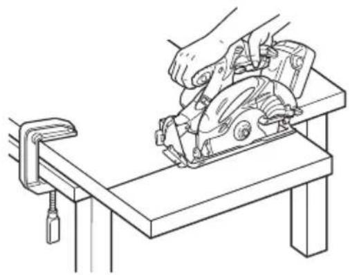
Since the saw blade will extend beyond the lower surface of the lumber, place the lumber on a workbench when cutting. If a square block is utilized as a workbench, select level ground to ensure it is properly stabilized. An unstable workbench will result in hazardous operation. (Fig.3)
To avoid possible accident, always ensure that the portion of lumber remaining after cutting is securely anchored or held in position.
- Be careful of brake kickback.
This circular saw features an electric brake that functions when the switch is released. As there is some kickback when the brake functions, be sure to hold the main body securely.
-
Do not fix and secure the switch lock. Besides, keep your finger off the switch trigger when the circular saw is being carried around. Otherwise, the main body switch can be inadvertently turned ON, resulting in unexpected accidents.
-
Prior to cutting operation, make sure the material you are going to cut. If the material to be cut is expected to generate harmful / toxic dusts, make sure the dust bag or appropriate dust extraction system is connected with dust outlet tightly.
Wear the dust mask additionally, if available.
-
Before starting to saw, ensure that the saw blade has reached full speed revolution.
-
Should the saw blade be stopped or made an abnormal noise during operation, turn off the switch immediately.
-
Twisting and forcibly pressing the saw during cutting can result in unreasonable pressure on the motor, so try to go straight quietly.
-
Avoid cutting operation in a state where the base bottom is all oat from the material being cut. Otherwise, the motor can get locked.
-
Preparing and checking the work environment. Make sure that the work site meets all the conditions laid forth in the precautions.
-
Make sure that the battery is installed firmly. If it is as all loose it could come off and cause an accident.
-
When finished with a job, pull out the battery from the main body.
-
After having attached the saw blade, reconfirm that the lock lever is firmly secured in the prescribed position.
-
If the left-hand bolt is worked using other tools than the provided box wrench, excessive tightening and insufficient tightening may take place resulting in injury.
-
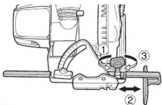
After adjusting cutting depth, make sure to securely tighten the butterfly nut. Failure to do so may result in injury. (Fig.4)
-
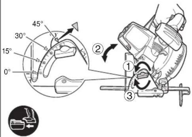
After adjusting the angle of inclination, make sure to securely tighten the butterfly nut. Failure to do so may result in injury. (Fig.5)
-
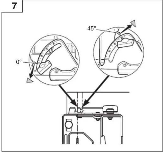
Values of the inclined gauge provided on the base merely serve as a rough guideline. For cutting operation at an inclined posture, use the circular saw after adjusting the angle between the base and the saw blade with a protractor, etc.
- Pull out battery before carrying out any adjustment, servicing or maintenance.
- Ensure that the switch is in the OFF position. If the battery installed to power tool while the switch is in the ON position, the power tool will start operating immediately, which could cause a serious accident.
- If the main body is left as it is with the battery inserted, there can be a case where the [switch lock] touches the floor and/or wall surface and lights up continuously, depending on the direction of the body. Be careful, since continuous lighting can easily make a full-charged battery go dead.
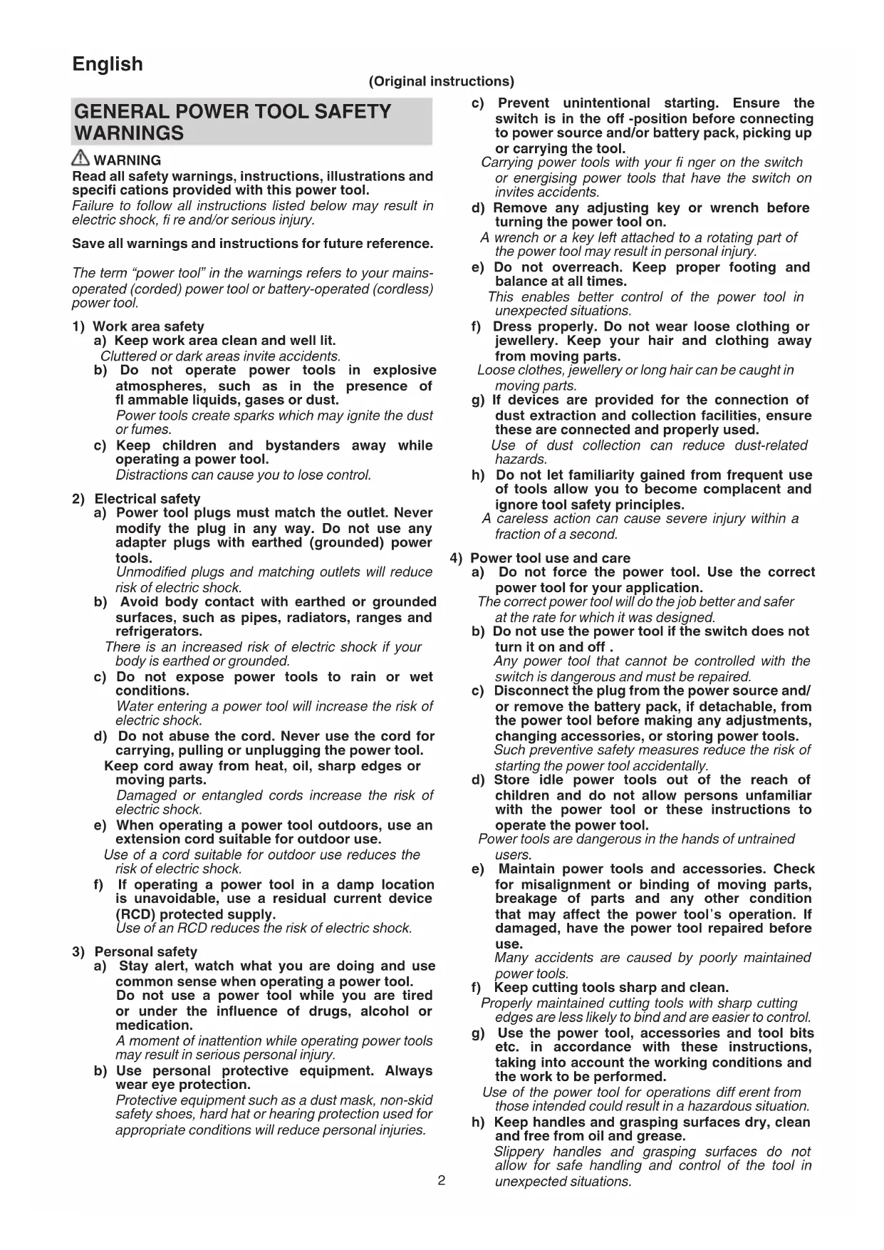
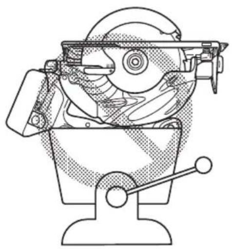
- Never attempt to saw with the circular saw held upside down in a vise. This is extremely dangerous and can lead to serious accidents (Fig. 11).
- Keep the light ON during cutting operation only. If it is lit ON in other cases, the main body switch can be inadvertently turned ON, resulting in unexpected accidents.
- Immediately after the light is turned OFF, the bulb retains high temperature. Make sure to cool down the light bulb thoroughly before replacing it so as to prevent burns.
- When replacing the light bulb, check the shape of base as well as the rating (12 V, 5 W), and then carry out perfect mounting. Otherwise, the light bulb can come off and/or cause overheat.
- Check the exterior and ensure that there is no damage.
- Use a saw blade with a displayed rotational speed equal to or higher than the rotational speed of the tool.
- Use a saw blade that suits each different cutting material.
- Always use the tool and battery at temperatures between -5^ and 40^ .
CAUTION ON LITHIUM-ION BATTERY
To extend the lifetime, the lithium-ion battery equips with the protection function to stop the output.
In the cases of 1 to 3 described below, when using this product, even if you are pulling the switch, the motor may stop. This is not the trouble but the result of protection function.
- When the battery power remaining runs out, the motor stops.
In such a case, charge it up immediately. - If the tool is overloaded, the motor may stop. In this case, release the switch of tool and eliminate causes of overloading. After that, you can use it again.
- If the battery is overheated under overload work, the battery power may stop.
In this case, stop using the battery and let the battery cool. After that, you can use it again.
Furthermore, please heed the following warning and caution.
WARNING
In order to prevent any battery leakage, heat generation, smoke emission, explosion and ignition beforehand, please be sure to heed the following precautions.
-
Make sure that swarf and dust do not collect on the battery.
During work make sure that swarf and dust do not fall on the battery.
○ Make sure that any swarf and dust falling on the power tool during work do not collect on the battery.
○ Do not store an unused battery in a location exposed to swarf and dust.
Before storing a battery, remove any swarf and dust that may adhere to it and do not store it together with metal parts (screws, nails, etc.). -
Do not pierce battery with a sharp object such as a nail, strike with a hammer, step on, throw or subject the battery to severe physical shock.
- Do not use an apparently damaged or deformed battery.
- Do not use the battery in reverse polarity.
- Do not connect directly to an electrical outlets or car cigarette lighter sockets.
- Do not use the battery for a purpose other than those specified.
- If the battery charging fails to complete even when a specified recharging time has elapsed, immediately stop further recharging.
- Do not put or subject the battery to high temperatures or high pressure such as into a microwave oven, dryer, or high pressure container.
- Keep away from fi re immediately when leakage or foul odor are detected.
- Do not use in a location where strong static electricity generates.
- If there is battery leakage, foul odor, heat generated, discolored or deformed, or in any way appears abnormal during use, recharging or storage, immediately remove it from the equipment or battery charger, and stop use.
- Do not immerse the battery or allow any fluids to flow inside. Conductive liquid ingress, such as water, can cause damage resulting in fire or explosion. Store your battery in a cool, dry place, away from combustible and fl ammable items. Corrosive gas atmospheres must be avoided.
CAUTION
- If liquid leaking from the battery gets into your eyes, do not rub your eyes and wash them well with fresh clean water such as tap water and contact a doctor immediately.
If left untreated, the liquid may cause eye-problems.
- If liquid leaks onto your skin or clothes, wash well with clean water such as tap water immediately.
There is a possibility that this can cause skin irritation.
- If you find rust, foul odor, overheating, discolor, deformation, and/or other irregularities when using the battery for the first time, do not use and return it to your supplier or vendor.
WARNING
If a conductive foreign matter enters in the terminal of lithium ion battery, the battery may be shorted, causing fire. When storing the lithium ion battery, obey surely the rules of following contents.
- Do not place conductive debris, nail and wires such as iron wire and copper wire in the storage case.
To prevent shorting from occurring, load the battery in the tool or insert securely the battery cover for storing until the ventilator is not seen.
SYMBOLS
WARNING
The following show symbols used for the machine. Be sure that you understand their meaning before use.
 | C18DSL: Cordless Circular Saw |
 | To reduce the risk of injury, user must read instruction manual. |
 | Always wear eye protection. |
 | Always wear hearing protection. |
 | Only for EU countriesDo not dispose of electric tools together with household waste material!In observance of European Directive 2012/19/EU on waste electrical and electronic equipment and its implementation in accordance with national law, electric tools that have reached the end of their life must be collected separately and returned to an environmentally compatible recycling facility. |
| V Rated voltage | |
| n_0 | No-load speed |
 | Switching ON |
 | Switching OFF |
 | Disconnect the battery |
 | Battery capacity |
 | The battery remaining power is nearly empty.Recharge the battery soonest possible |
 | The battery remaining power is a half. |
 | The battery remaining power is enough. |
 | Prohibited action |
STANDARD ACCESSORIES
In addition to the main unit (1 unit), the package contains the accessories listed on page 191.
Standard accessories are subject to change without notice.
APPLICATIONS
Cutting various types of wood.
SPECIFICATIONS
| Model C18DSL | |||
| Voltage 18 V | |||
| No-Load Speed 3400 min | -1 | ||
| Capacity Cutting depth | 90° 57 mm | ||
| 45° 40 mm | |||
| Light bulb 12 V, 5 W | |||
| Weight* 3.1 – 3.7 kg | |||
* According to EPTA-Procedure 01/2014
Depending on attached battery.
The heaviest weight is measured with BSL1860.
NOTE
Due to HiKOKI's continuing program of research and development, the specifications herein are subject to change without prior notice.
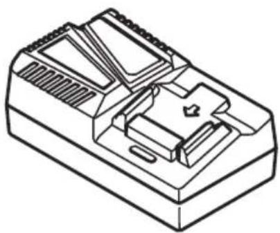
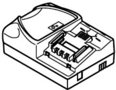
CHARGING
Before using the power tool, charge the battery as follows.
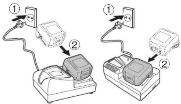
1. Connect to the power source. (Fig. 2)
When charging the battery from an AC power source
○ Connect the charger's power cord to the receptacle.
When connecting the plug of the charger to a receptacle, the pilot lamp will blink in red (At 1-second intervals).
CAUTION
Do not use the electrical cord if damaged. Have it repaired immediately.
When charging the battery from a DC 12V in-car power source (UC18YML2)
- Secure the battery charger in place in the car.
Use the strap supplied with the battery charger to fasten the battery charger in place and prevent it from moving inadvertently. (See Fig. 16)
CAUTION
Do not place the battery charger or battery under the driver's seat. Secure the battery charger in place to prevent it from moving inadvertently as this may lead to an accident.
natural_image
Diagram of a vehicle's cross symbol (no text or labels present)
natural_image
Line drawing of a mechanical assembly with no visible text or symbolsFig. 16
○ Insert the cigarette lighter connecting plug into the cigarette lighter socket.
If the plug is loose and falls out of the cigarette lighter socket, repair the socket. As the socket may be faulty, you are recommended to contact your local car dealer. Continued use of the socket may result in an accident due to overheating.
- Insert the battery into the charger. (Fig. 2)
Firmly insert the battery into the charger.
3. Charging
When inserting a battery in the charger, charging will commence and the pilot lamp will light continuously in red.
When the battery becomes fully recharged, the pilot lamp will blink in red. (At 1-second intervals) (See Table 1)
● Pilot lamp indication
The indications of the pilot lamp will be as shown in Table 1, according to the condition of the charger or the rechargeable battery.
Table 1
| Indications of the pilot lamp | |||
| The pilot lamp lights or blinks. | Before charging | Blinks (red) | Lights for 0.5 seconds. Does not light for 0.5 seconds. (off for 0.5 seconds) |
| While charging | Lights (red) | Lights continuously | |
| Charging complete | Blinks (red) | Lights for 0.5 seconds. Does not light for 0.5 seconds. (off for 0.5 seconds) | |
| Charging impossible | Flickers (red) | Lights for 0.1 seconds. Does not light for 0.1 seconds. (off for 0.1 seconds) | |
| Overheat standby | Lights (green) (UC18YML2) | Lights continuously | |
| Blinks (red) (UC18YFSL) | Lights for 1 second. Does not light for 0.5 seconds. (off for 0.5 seconds) | ||
| Charging with in-car power source impossible (UC18YML2) | Blinks (green) | Lights for 0.5 seconds. Does not light for 0.5 seconds. (off for 0.5 seconds) | |
NOTE: When standby for cooling battery, UC18YML2 / UC18YFSL cools the overheated battery by cooling fan. (However, the cooling fan does not function when charging the battery with a DC 12V in-car power source.)
● Regarding the temperatures and charging time of the battery.
The temperatures and charging time will become as shown in Table 2
Table 2
| Battery\Charger | UC18YFSL | UC18YML2(AC/DC)*1 | |
| Charging voltage V 14.4 V – 18 V | |||
| Weight kg 0.5 0.7 | |||
| Temperatures at which the battery can be recharged | 0°C – 50°C | ||
| Charging time for battery capacity, approx.(At 20°C) | |||
| 1.3 Ah | min. | 20 | 20 / 50 |
| 1.5 Ah | min. | 22 | 22 / 60 |
| 2.0 Ah | min. | 30 | 30 / 80 |
| 2.5 Ah | min. | 35 | 35 / 100 |
| 3.0 Ah | min. | 45 | 45 / 120 |
| 4.0 Ah | min. | 60 | 60 / 160 |
| 5.0 Ah | min. | 75 | 75 / 200 |
| Number of battery cells 4 – 10 | |||
*1 AC power supply / DC 12V (in-car) power supply
NOTE
The recharging time may vary according to the ambient temperature and power source voltage.
Especially, using a DC 12V in-car power source may require longer recharging time at high temperatures.
-
Disconnect the charger's power cord from the receptacle or cigarette lighter socket.
-
Hold the charger firmly and pull out the battery. NOTE
Be sure to pull out the battery from the charger after use, and then keep it.
CAUTION
If the battery is charged while it is heated because it has been left for a long time in a location subject to direct sunlight or because the battery has just been used, the pilot lamp of the charger lights up green or lights for 1 second, does not light for 0.5 seconds (off for 0.5 seconds). In such a case, first let the battery cool, then start charging.
When the pilot lamp flickers in red (at 0.2-seconds intervals), check for and take out any foreign objects in the charger's battery connector. If there are no foreign objects, it is probable that the battery or charger is malfunctioning. Take it to your authorized Service Center.
English
○ Since the built-in micro computer takes about 3 seconds to confirm that the battery being charged with charger is taken out, wait for a minimum of 3 seconds before reinserting it to continue charging. If the battery is reinserted within 3 seconds, the battery may not be properly charged.
○ Check the voltage of the in-car power source when the pilot lamp fl ickers in green (every 0.2 seconds) continuously. (UC18YML2)
If the voltage is 12V or lower, it indicates that the car battery has weakened and cannot be charged.
☐ If the pilot lamp does not blink in red (every second) even though the charger cord or cigarette lighter connecting plug is connected to the power, it indicates that the protection circuit of the charger may be activated.
Remove the cord or plug from the power and then connect it again after 30 seconds or so. If this does not cause the pilot lamp to blink in red (every second), please take the charger to the HiKOKI Authorized Service Center.
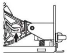
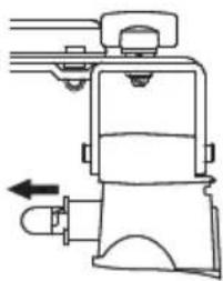
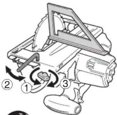
MOUNTING AND OPERATION
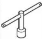
| Action Figure Page | ||
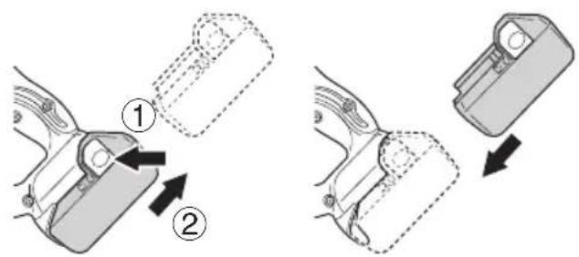
| Removing and inserting the battery | 1 192 | |
| Charging 2 192 | ||
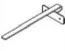
| How to secure material for cutting 3 | 192 | |
| Adjusting the cutting depth 4 192 | ||
| Adjusting the angle of inclination 5 | 192 | |
| Regulating the guide 6 192 | ||
| Cutting line 7 193 | ||
| Switch operation 8 193 | ||
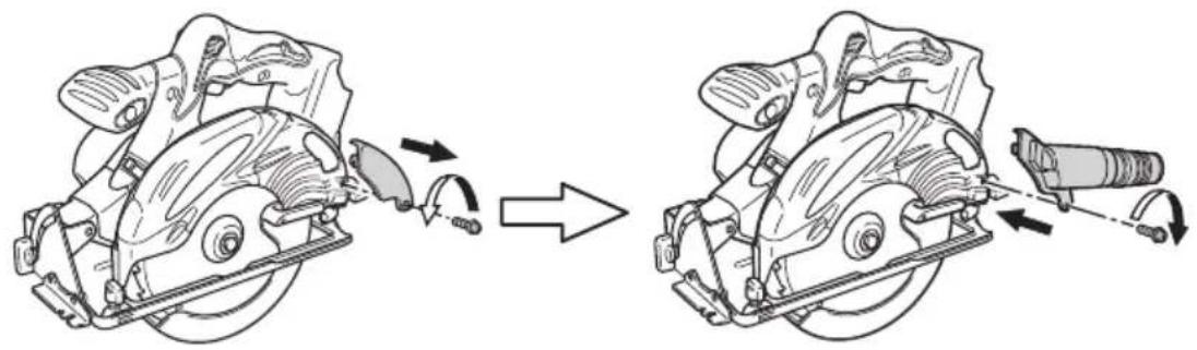
| Dismounting the saw blade | 9 193 | |
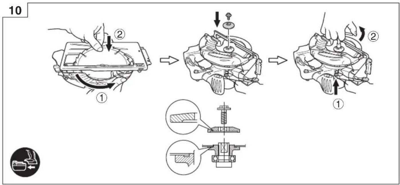
| Mounting the saw blade | 10 | 193 |
| Prohibited methods of use (Fixed upside down with vise) | 11 | 194 |
| Remaining battery indicator | 12 | 194 |
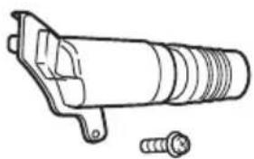
| Mounting the dust collector set | 13 | 194 |
| Replacing light bulb | 14 | 194 |
| Adjusting the base and saw blade to maintain perpendicularity | 15 | 194 |
| Selecting accessories | — | 195 |
MAINTENANCE AND INSPECTION
1. Inspecting the saw blade
Since use of as dull saw blade will degrade efficiency and cause possible motor malfunction, sharpen or replace the saw blade as soon as abrasion is noted.
CAUTION
If a dull saw blade is used, reactive force is increased during cutting operation. Avoid the use of the dull saw blade without repair.
2. Inspecting the mounting screws
Regularly inspect all mounting screws and ensure that they are properly tightened. Should any of the screws be loose, retighten them immediately. Failure to do so could result in serious hazard.
3. Motor unit maintenance
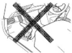
The motor winding is an important part of this tool. Avoid damaging and be careful to avoid contact with cleaning oil or water.
After 50 hours of use, clean the motor by blowing into the ventilation holes of the motor housing with dry air from an air gun or other tool (Fig. 17).
Dust or particle accumulation in the motor can result in damage.
4. Inspecting and maintaining the lower guard
Always make sure that the lower guard moves smoothly. In the event of any malfunction, immediately repair the lower guard.
For cleaning and maintenance, use an air gun or other tool to blow clean the space between the lower guard and gear cover as well as the rotation part of the lower guard with dry air (Fig. 17).
Doing so is effective for the emission of chips or other particles.
Accumulation of chips or other particles around the lower guard may result in malfunction or damage.
WARNING
To prevent dust inhalation or eye irritation, wear protective safety goggles and a dust mask when using an air gun or other tool to clean the lower guard, ventilation holes or other parts of the product.
text_image
Ensure smooth movement of lower guard Rotation part of the lower guard Space between lower guard and gear cover Housing vent Air gunFig. 17
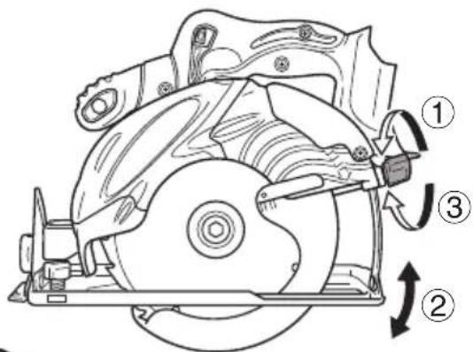
5. Adjusting the base and saw blade to maintain perpendicularity
The angle between the base and the saw blade has been adjusted to 90^ , however should this perpendicularity be lost for some reason, adjust in the following manner:
(1) Turn the base face up (Fig. 15) and loosen the wing-bolt.
(2) Apply a square to the base and the saw blade and turning the slotted set screw with a slotted-head screwdriver, shift the position of the base to produce the desired right angle.
6. Check for dust
Dust may be removed with a clean rag or a cloth dampened with soapy water.
Do not use bleach, chlorine, gasoline or thinner, for they may damage the plastics.
7. Storage
Storing in a place below 40^ C and out of the reach of children.
NOTE
Storing lithium-ion batteries.
Make sure the lithium-ion batteries have been fully charged before storing them.
Prolonged storage (3 months or more) of batteries with a low charge may result in performance deterioration, significantly reducing battery usage time or rendering the batteries incapable of holding a charge.
However, significantly reduced battery usage time may be recovered by repeatedly charging and using the batteries two to five times.
If the battery usage time is extremely short despite repeated charging and use, consider the batteries dead and purchase new batteries.
8. Service and repairs
All quality power tools will eventually require servicing or replacement of parts because of wear from normal use. To assure that only genuine replacement parts must be used, all service and repairs must be performed by a HiKOKI AUTHORIZED SERVICE CENTER, ONLY.
CAUTION
In the operation and maintenance of power tools, the safety regulations and standards prescribed in each country must be observed.
Important notice on the batteries for the HiKOKI cordless power tools
Please always use one of our designated genuine batteries. We cannot guarantee the safety and performance of our cordless power tool when used with batteries other than these designated by us, or when the battery is disassembled and modified (such as disassembly and replacement of cells or other internal parts).
GUARANTEE
We guarantee HiKOKI Power Tools in accordance with statutory/country specific regulation. This guarantee does not cover defects or damage due to misuse, abuse, or normal wear and tear. In case of complaint, please send the Power Tool, undismantled, with the GUARANTEE CERTIFICATE found at the end of this Handling instruction, to a HiKOKI Authorized Service Center.
Information concerning airborne noise and vibration
The measured values were determined according to EN62841 and declared in accordance with ISO 4871.
Measured A-weighted sound power level: 103 dB (A) Measured A-weighted sound pressure level: 92 dB (A) Uncertainty K: 3 dB (A).
Wear hearing protection.
Vibration total values (triax vector sum) determined according to EN62841.
Cutting chipboard:
Vibration emission value a_h=2.0 m/s^2
Uncertainty K = 1.5 m/s ^4
The declared vibration total value has been measured in accordance with a standard test method and may be used for comparing one tool with another. It may also be used in a preliminary assessment of exposure.
WARNING
☐ The vibration emission during actual use of the power tool can differ from the declared total value depending in the ways in which the tool is used.
○ Identify safety measures to protect the operator that are based on an estimation of exposure in the actual conditions of use (taking account of all parts of the operating cycle such as the times when the tool is switched off and when it is running idle in addition to the trigger time).
NOTE
Due to HiKOKI's continuing program of research and development, the specifications herein are subject to change without prior notice.
ALLGEMEINE
natural_image
Pure mechanical cross-section diagram without any text, numbers, or symbols
natural_image
Line drawing of a mechanical assembly with a clamped component (no text or symbols)Abb. 16
Vibrationsemissionswert a_h = 2,0 m/s^2
natural_image
Technical line drawing showing a mechanical assembly with a cross symbol (no text or labels)Fig. 16
natural_image
Technical line drawing showing a cross-shaped object and a mechanical component (no text or symbols)Fig. 16
VEILIGHEIDSWAARSCHUWINGEN
natural_image
Pure mechanical cross-section diagram without any text, numbers, or symbols
natural_image
Line drawing of a mechanical component with no visible text or symbolsAfb. 16
natural_image
Technical line drawing showing a car wheel and its seatbelt mechanism (no text or symbols)Fig. 16
natural_image
Pure mechanical cross-section diagram without any text, numbers, or symbols
natural_image
Pure mechanical diagram showing a linkage or fastener mechanism without any text, numbers, or symbolsFig. 16
natural_image
Diagram of a vehicle with a cross symbol crossed out, no text or labels present
natural_image
Line drawing of a mechanical assembly with no visible text or symbolsBild 16
natural_image
Technical line drawing of a mechanical component with a diagonal cross mark (no text or symbols)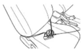
natural_image
Pure mechanical diagram showing a lever and pivot mechanism without any text or symbolsFig. 16
natural_image
Technical line drawing showing mechanical assembly with a cross symbol (no text or labels)Fig. 16
○ Sett tilkoplingsledningen i bilens sigarettenner.
VEDLIKEHOLD OG INSPEKSJON
1. Inspisere sagbladet
natural_image
Technical line drawing showing mechanical assembly with crosshair overlay (no text or symbols)Kuva 16
natural_image
Technical line drawing showing mechanical assembly with a cross symbol (no text or labels)Eik. 16
natural_image
Diagram of a vehicle's cross symbol crossed out, no text or labels present
natural_image
Line drawing of a mechanical assembly with no visible text or symbolsRys. 16
natural_image
Technical line drawing showing two mechanical components with a cross symbol (no text or labels)- ábra
natural_image
Technical line drawing showing mechanical assembly with a cross symbol (no text or labels)obr. 16
natural_image
Diagram of a vehicle's cross symbol crossed out, no text or labels present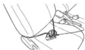
natural_image
Pure mechanical diagram showing a lever and pivot point without any text, numbers, or symbolsŞekil 16
natural_image
Technical line drawing showing mechanical assembly with a cross symbol (no text or labels)Fig. 16
natural_image
Diagram of a car interior with a diagonal line crossing through the window (no text or symbols)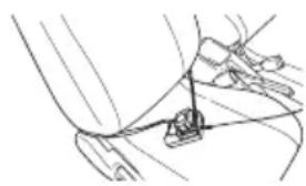
natural_image
Line drawing of a mechanical assembly with a tool inserted into a component (no text or symbols)Sl. 16
STANDARDNA OPREMA
natural_image
Technical line drawing showing mechanical assembly with a cross symbol (no text or labels)Obr. 16
○ Vložte zástrčku do cigaretového zapal'ovača do zásuvky zapal'ovača vo vozidle.
natural_image
Technical line drawing showing a hand holding a car with a cross symbol, and a close-up of the seat assembly (no text or labels)Фиг. 16
natural_image
Diagram of a car interior with a diagonal cross mark (no text or symbols)
natural_image
Line drawing of a mechanical assembly with a clamping tool inserted into a component (no text or symbols)Sl. 16
○ Stavite priključak upaljača za cigarette u utičnicu upaljača za cigarette.
natural_image
Technical line drawing showing mechanical assembly with cross symbol (no text or labels)Slika 16
O Utaknite utikač u utičnicu upaljača.
 |  |  |  |  |  |  |  | |
| C18DSL 1 | 1 2 1 1 1 1 | |||||||
| C18DSL (NN) | 1 | 1 | 1 | - | - | - |
1
text_image
Diagram showing two steps of a mechanical locking or disassembly process, labeled with numbered instructions.2
text_image
Diagram showing two connected devices with labeled components, likely illustrating a device setup or connection.UC18YML2 UC18YFSL
3
natural_image
Line drawing of a hand operating a manual cutting machine on a workbench (no text or symbols)4
text_image
Technical diagram of a mechanical device with numbered parts and directional arrows indicating motion or assembly.
5
text_image
45° 30° 15° 0° ② ① ③6
text_image
Technical diagram of a mechanical assembly with numbered parts and directional arrows indicating motion or assembly.
text_image
7 0° 45° 0° 45°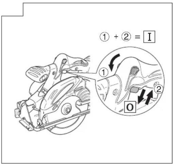
text_image
① + ② = I ① ② O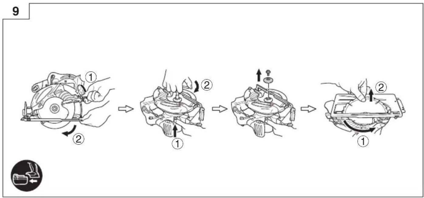
flowchart
graph TD
    A["Step 1: Hand brake"] --> B["Step 2: Rotation of brake"]
    B --> C["Step 3: Rotation of brake"]
    C --> D["Step 4: Rotation of brake"]
    D --> E["Step 5: Rotation of brake"]
text_image
10 ① ② ① ②11 12
natural_image
Technical line drawing of a mechanical device with gears and a lever (no text or symbols)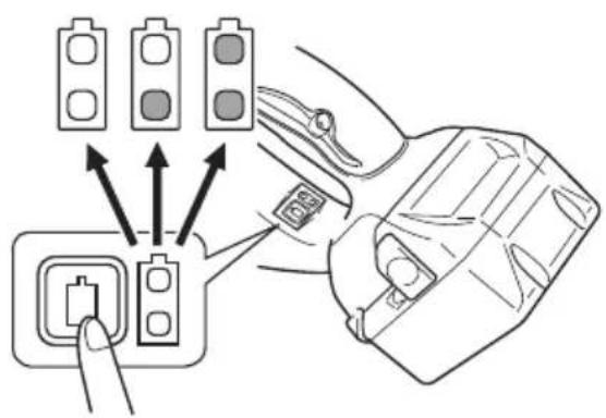
text_image
Diagram showing car seatbelt switch connections with three traffic lights and a connector pin, illustrating vehicle safety instructions.13
natural_image
Diagram showing mechanical assembly before and after disassembly, with no visible text or symbols
14 15
natural_image
Mechanical assembly diagram showing a clamping mechanism with no visible text or symbols→
natural_image
Pure mechanical diagram of a lever mechanism without any text, numbers, or symbols→
natural_image
Pure mechanical diagram of a device without any text, numbers, or symbols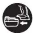
text_image
Diagram of a car interior showing three labeled parts: wheel, handle, and foot with directional arrows indicating rotation or movement.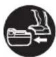
natural_image
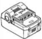
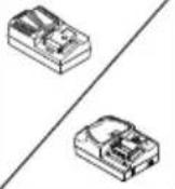
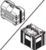
Isometric line drawing of a mechanical component or housing with internal compartments and mounting features (no text or symbols)UC18YFSL (14,4 V - 18 V)
natural_image
Line drawing of a device casing with internal components (no text or symbols)UC18YML2 (14,4 V - 18 V)
natural_image
Circular mechanical component with jagged edge and central hole (no text or symbols)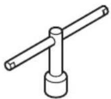
natural_image
Simple line drawing of a mechanical lever or support structure (no text or symbols)940543
natural_image
Simple line drawing of a metal rod with two flanged ends (no text or symbols)302756D30: 324295
natural_image
Technical line drawing of a mechanical component with threaded body and mounting bracket (no text or symbols)
329897324580
natural_image
Isometric line drawing of a mechanical component with layered structure (no text or symbols)
natural_image
Technical line drawing of a mechanical housing or enclosure with internal components (no text or symbols)
natural_image
Isometric line drawing of a 3D electronic component or housing (no text or symbols)330274 337529337528

natural_image
Line drawing of a quill pen in an inkwell (no text or symbols)| English Dansk Română | ||||
| GUARANTEE CERTIFICATE1 Model No.2 Serial No.3 Date of Purchase4 Customer Name and Address5 Dealer Name and Address(Please stamp dealer name and address) | GARANTIBEVIS1 Modelnummer2 Serienummer3 Købsdato4 Kundes navn og adresse5 Forhandlers navn og adresse(Indsæt stempel med forhandlers navn og adresse) | CERTIFICAT DE GARANTIE1 Model nr.2 Nr. de serie3 Data cumpărării4 Numele și adresa clientului5 Numele și adresa distribuitorului(Vă rugăm aplicați ștampila cu numele și adresa distribuitorului) | ||
| Deutsch Norsk Slovenščina | ||||
| GARANTIESCHEIN1 Modell-Nr.2 Serien-Nr.3 Kaufdatum4 Name und Anschrift des Kunden5 Name und Anschrift des Händlers(Bitte mit Namen und Anschrift des Handlers abstempeln) | GARANTISERTIFIKAT1 Modellnr.2 Serienr.3 Kjøpsdato4 Kundens navn og adresse5 Forhandlerens navn og adresse(Vennligst stemple forhandlerens navn og adresse) | GARANCIJSKO POTRDILO1 Št. modela2 Serijska št.3 Datum nakupa4 Ime in naslov kupca5 Ime in naslov prodajalca(Prosimo vtsnite žig z imenom in naslovom prodajalca) | ||
| Français Suomi Slovenčina | ||||
| CERTIFICAT DE GARANTIE1 No. de modèle2 No de série3 Date d'achat4 Nom et adresse du client5 Nom et adresse du revendeur(Cachet portant le nom et l'adresse du revendeur) | TAKUUTODISTUS1 Malli nro2 Sarja nro3 Ostopäivämäärä4 Asiakkaan nimi ja osoite5 Myyjän nimi ja osoite(Leimaa myyjän nimi ja osoite) | ZÁRUČNÝ LISTA1 Č. modelu2 Sériové č.3 Dátum zakúpenia4 Meno a adresa zákaznika5 Názov a adresa predajcu(Pečiatka s názvom a adresou predajcu) | ||
| Italiano Ελληνικά Βългарски | ||||
| CERTIFICATO DI GARANZIA1 Modello2 N° di serie3 Data di acquisto4 Nome e indirizzo dell'acquirente5 Nome e indirizzo del rivenditore(Si prega di apporre il timbro con questi dati) | ПІЗТОПОІНТІКО ЕГГУНЄНЕ1 Ap. Movtėlou2 Aŭξων Ap.3 Нμερομηνία αγοράς4 ́Оvoμα και διεύθυνση πελάτη5 ́Оvoμα και διεύθυνση μεταπωλητή(Παρακαλούμε να χρησιμοποιηθεί σφραγίδα) | ГАРАНЦИОНЕН СЕРТИФИКАТ1 Модел No2 Сериен No3 Дата за закупуване4 Име и адрес на клиента5 Име и адрес на търговеца(Моля, отпечатайте името и адрес на дильра) | ||
| Nederlands Polski Srpski | ||||
| GARANTIEBEWIJS1 Modelnummer2 Serienummer3 Datum van aankoop4 Naam en adres van de gebruiker5 Naam en adres van de handelaar(Stempel a.u.b. naam en adres vande de handelaar) | GWARANCJA1 Model2 Numer seryjny3 Data zakupu4 Nazwa klienta i adres5 Nazwa dealera i adres(Pieczęć punktu sprzedaży) | GARANTNI SERTIFIKAT1 Br. modela.2 Serijski br.3 Datum kupovine4 Ime i adresa kupca5 Ime i adresa prodavca(Molimo da stavite pečat na ime i adresu trgovca) | ||
| Español Magyar Hrvatski | ||||
| CERTIFICADO DE GARANTÍA1 Número de modelo2 Número de serie3 Fecha de adquisición4 Nombre y dirección del cliente5 Nombre y dirección del distribuidor(Se ruega poner el sello del distribuidor con su nombre y dirección) | GARANCIA BIZONYLAT1 Tipusszám2 Sorozatszám3 A vásárlás dátuma4 A Vásárló neve és címe5 A Kereskedő neve és címe(Kárjük ide olhelyezni a Kereskedő nevének és címének pecsétjét) | JAMSTVENI CERTIFIKAT1 Br modela.2 Serijski br.3 Datum kupnje4 Ime i adresa kupca5 Ime i adresa trgovca(Molimo stavite pečat na ime i adresu trgovca) | ||
| Português Čeština | ||||
| CERTIFICADO DE GARANTIA1 Número do modelo2 Número do série3 Data de compra4 Nome e morada do cliente5 Nome e morada do distribuidor(Por favor, carimbe o nome e morada do distribuidor) | ZÁRUČNÍ LIST1 Model č.2 Série č.3 Datum nákupu4 Jméno a adresa zákazníka5 Jméno a adresa prodejce(Prosíme o razitko se jménem a adresou prodejce) | |||
| Svenska Türkçe | ||||
| GARANTICERTIFIKAT1 Modellnr2 Serienr3 Inköpsdatum4 Kundens namn och adress5 Försäljarens namn och adress(Stámpla försäljarens namn och adress) | GARANTI SERTÍFÍKASI1 Model No.2 Seri No.3 Satin Alma Tarihi4 Müşteri Adı ve Adresi5 Bayi Adı ve Adresi(Lütfen bayi adini ve adresini kaşe olarak basin) | |||
HiKOKI
| 1 | |
| 2 | |
| 3 | |
| 4 | |
| 5 |
Siemensring 34, 47877 willich, Germany
Tel: +49 2154 49930
Fax: +49 2154 499350
URL: http://www.hikoki-powertools.de
Hikoki Power Tools Netherlands B.V.
Brabanthaven 11, 3433 PJ Nieuwegein, The Netherlands
Tel: +31 30 6084040
Fax: +31 30 6067266
URL: http://www.hikoki-powertools.nl
Hikoki Power Tools (U.K.) Ltd.
Precedent Drive, Rooksley, Milton Keynes, MK 13, 8PJ,
United Kingdom
Tel: +44 1908 660663
Fax: +44 1908 606642
URL: http://www.hikoki-powertools.uk
Hikoki Power Tools France S.A.S.
Hikoki Power Tools Belgium N.V./S.A.
Koningin Astridlaan 51, B-1780 Wemmel, Belgium
Tel: +32 2 460 1720
Fax: +32 2 460 2542
URL http://www.hikoki-powertools.be
Hikoki Power Tools Italia S.p.A
Via Piave 35, 36077, Altavilla Vicentina (VI), Italy
Tel: +39 0444 548111
Fax: +39 0444 548110
URL: http://www.hikoki-powertools.it
Hikoki Power Tools Ibérica, S.A.
C/ Puigbarral, 26-28, Pol. Ind. Can Petit, 08227 Terrassa
(Barcelona), Spain
Tel: +34 93 735 6722
Fax: +34 93 735 7442
URL: http://www.hikoki-powertools.es
Kjeller Vest 7, N-2007 Kjeller, Norway
Tel: (+47) 6692 6600
Fax: (+47) 6692 6650
URL: http://www.hikoki-powertools.no
Hikoki Power Tools Sweden AB
Rotebergsvagen 2B SE-192 78 Sollentuna, Sweden
Tel: (+46) 8 598 999 00
Fax: (+46) 8 598 999 40
URL: http://www.hikoki-powertools.se
Hikoki Power Tools Denmark A/S
Lillebaeltsvej 90, 6715 Esbjerg N, Denmark
Tel: (+45) 75 14 32 00
Fax: (+45) 75 14 36 66
URL: http://www.hikoki-powertools.dk
Hikoki Power Tools Finland Oy
Tupalankatu 9, 15680 Lahti, Finland
Tel: (+358) 20 7431 530
Fax: (+358) 20 7431 531
URL: http://www.hikoki-powertools.fi
Hikoki Power Tools Hungary Kft.
Hikoki Power Tools Romania S.R.L.
Ring Road, No. 66, Mustang Traco Warehouses, Warehouse
No.1, Pantelimon City, 077145, Ilfov County, Romania
natural_image
Line drawing of a quill pen in an inkwell (no text or symbols)
natural_image
Line drawing of a quill pen in an inkwell (no text or symbols)| English Nederlands | ||
| EC DECLARATION OF CONFORMITYWe declare under our sole responsibility that Cordless Circular Saw, identified by type and specific identification code *1), is in conformity with all relevant requirements of the directives *2) and standards *3). Technical fi le at *4) – See below.The European Standard Manager at the representative office in Europe is authorized to compile the technical fi le.The declaration is applicable to the product affi xed CE marking. | EC VERKLARING VAN CONFORMITEITWij verklaren onder onze eigen verantwoordelijkheid dat Snoerloze cirkelzaagmachine, geïdentificeerd door het type en de specifieke identificatiecode*1), voldoet aan alle relevante bepalingen van de richtlijnen*2) en normen*3). Technische documentatie bij*4) – zie onder.De Europese Normen Manager bij de vertegenwoordiging in Europa is gemachtigd om het technisch dossier samen te stellen.Deze verklaring is van toepassing op producten voorzien van de CE-markeringen. | |
| Deutsch Español | ||
| EG-KONFORMITÄTSERKLÄRUNGWir erklären in alleiniger Verantwortung, dass die durch den Typ und den spezifischen Identifizierungscode *1) identifizierte Akku-Kreissäge allen einschlägigen Bestimmungen der Richtlinien *2) und Normen *3) entspricht. Technische Unterlagen unter *4) – Siehe unten.Die Leitung der repräsentativen Behörde für europäische Normen und Richtlinien ist berechtigt, die technischen Unterlagen zusammenzustellen.Die Erklärung gilt für die an dem Produkt angebrachte CE-Kennzeichnung. | DECLARACIÓN DE CONFORMIDAD DE LA CDEclaramos bajo nuestra única responsabilidad que la Sierra circular a batería, identificada por tipo y por código de identificación específico *1), está en conformidad con todas las disposiciones correspondientes de las directivas *2) y de las normas *3). Documentación técnica en *4) – Ver a continuación.El Director de Normas Europeas en la oficina de representación en Europa está autorizado para elaborar el expediente técnico.La declaración se aplica al producto con marcas de la CE. | |
| Français Português | ||
| DECLARATION DE CONFORMITE CENous déclarons sous notre entière responsabilité que la scie circulaire sans fil, identifiée par le type et le code d'identification spécifique *1) est en conformité avec toutes les exigences applicables des directives *2) et des normes *3). Dossier technique en *4) - Voir ci-dessous.Le Gestionnaire des normes européennes du bureau de représentation en Europe est autorisé à constituer le dossier technique.Cette déclaration s'applique aux produits désignés CE. | DECLARAÇÃO DE CONFORMIDADE CEDeclaramos, sob nossa única e inteira responsabilidade, que Serra Circular a Bateria, identificada por tipo e código de identificação específico *1), está em conformidade com todos os requerimentos relevantes das diretivas *2) e normas *3). Ficheiro técnico em *4)-Consulte abaixo.O Gestor de Normas Europeas no escritório de representação na Europa está autorizado a compilar o fi cheiro técnico.A declaração aplica-se aos produtos com marca CE. | |
| Italiano Svenska | ||
| DICHIARAZIONE DI CONFORMITÀ CEDichiariamo sotto la nostra esclusiva responsabilità che la sega circolare a batteria, identificata dal tipo e dal codice identificativo specifico *1), è conforme a tutti i requisiti delle direttive *2) e degli standard *3). Documentazione tecnica presso *4) – Vedere sotto.Il gestore delle norme europee presso l'ufficio di rappresentanza in Europa è autorizzato a compilare il fascicolo tecnico.La dichiarazione è applicabile ai prodotti cui sono applicati i marchi CE. | EG-DEKLARATION BETRÄFFANDE LIKFORMIGHETViförklarar på eget ansvar att denna batteridrivna cirkelsåg, identifierad enligt typ och särskild identifikationskod *1), överensstämmer med alla relevanta krav i direktiven *2) och standarderna *3). Teknisk fil enligt *4) – Se nedan.Den europeiska standardansvariga på representationskontoret i Europa är auktoriserad att sammenställa den tekniska fi len.Denna försäkran gäller för produkten med tillhörande CE-märkning. | |
| *1) C18DSL C337493T C337493R*2) 2006/42/EC, 2014/30/EU, 2014/35/EU, 2011/65/EU*3) EN62841-1:2015EN62841-2-5:2014EN60335-1:2012+A11:2014EN60335-2-29:2004+A2:2010EN55014-1:2006+A1:2009+A2:2011EN55014-2:1997+A1:2001+A2:2008 | ||
| *4) Representative offi ce in EuropeHikoki Power Tools Deutschland GmbHSiemensring 34, 47877 Willich, GermanyHead offi ce in JapanKoki Holdings Co., Ltd.Shinagawa Intercity Tower A, 15-1, Konan 2-chome,Minato-ku, Tokyo, Japan | 31. 5. 2019Naoto YamashiroEuropean Standard Manager  A. NakagawaCorporate Offi cer A. NakagawaCorporate Offi cer | |
| Dansk Polsk | ||
| EF-OVERENSSTEMMELSESERKLÆRINGVi erklærer os fuldstændige ansvarlige for, at den batteridrevne rundsav, identificeret ved type og specifik identifikationskode *1), er i overensstemmelse med alle relevante krav i direktiverne *2) og standarderne *3). Teknisk fi i *4) – Se nedenfor.Lederen af europæiske standarder på repræsentationskontoret i Europa er bemyndiget til at kompilere den tekniske fi l.Erklæringen gælder produktet, der er mærket med CE. | DEKLARACJA ZGODNOŚCI Z WEOświadczamy na własną wyłączną odpowiedzialność, że Akumulatorowa piła tarczowa podanego typu i oznaczona unikalnym kodem identyfikacyjnym *1) jest zgodna z wszystkimi właściwymi wymogami dyrektyw *2) i norm *3). Dokumentacja techniczna w *4) – Patrz poniżej.Menedżer Norm Europejskich przedstawicielstwa firmy w Europie jest upoważniony do sporządzania dokumentacji technicznej.Niniejsza deklaracja ma zastosowanie do produktu opatzonego znakiem CE. | |
| Norsk Magyar | ||
| EF'S ERKLÆRING OM OVERENSSTEMMELSEVi erklærer på eget ansvar at batteridrevet sirkelsag, identifisert etter type og spesifikk identifikasjonskode *1), er i samsvar med alle relevante krav i direktiver *2) og standarder *3). Teknisk fil under *4)- Se nedenfor.Styreren for europeiske standarder ved representantkontoret i Europa er autorisiert til å kompilere den tekniske fi len.Erklæringen gjelder for CE-merket på produktet. | EK MEGFELELŐSÉGI NYILATKOZATA kizárólagos felelősségünkre kijelentjük, hogy az Akkus körfürész, amely típus és egyedi azonosító kód *1) alapján azonosított, megfelel az irányelvek vonatkozó követelményeinek *2) és szabványainak *3). Műszaki fájl a *4) - Lásd alább.Az EU képviseleti iroda európai szabványügyi menedzsere jogosult a műszaki dokumentáció összeállítására.Jelen nyilatkozat a terméken feltüntetett CE jelzésre vonatkozik. | |
| Suomi Češtiņa | ||
| EY-ILMOITUS YHDENMUKAISUUDESTAVakuutamme yksinomaisella vastuullamme, että akkutoiminen pyőrösaha, joka identifioidaan tyypin ja erityisen tunnistuskoodin *1) perusteella, on kaikkien direktlivien *2) ja standardien *3) asiaankuuluvien vaatimusten mukainen. Tekninen tiedosto kohdassa *4) – katso alta.Eurooppalaisten standardien hallintaelin Euroopan edustustossa on valtuutettu kokoamaan teknisen tiedoston.Ilmoitus on sovellettavissa tuotteeseen kiinnitettyyn CE-merkintään. | PROHLÁŠENÍ O SHODĚ S ESProhlašujeme na svou výhradní zodpovědnost, že akku kotoučová pila, identifikovaná podle typu a specifického identifikačního kódu *1), je v souladu se všemi příslušnými požadavky směrníc *2) a norem *3). Technický soubor *4) - viz niže.K sestavení technické dokumentace je oprávněn manažer pro evropské standardy v evropském obchodním zastoupení.Toto prohlášení plati pro výrobek označený značkou CE. | |
| Ελληνικά Türkçe | ||
| EK ΔΗΛΩΣΗ ΕΝΑΡΜΟΝΙΣΜΟΥΔηλώνουμε με αποκλειστική μας ευθύνη ότι το Δισκοπρίονο μπαταρίας, το οποίο προσδιορίζεται από τον τύπο και ειδικό αναγνωριστικό κωδικό *1), είναι σύμφωνο με όλες τις σχετικές απαιτήσεις των Οδηγιών *2) και με τα σχετικά πρότυπα *3). Τεχνικό Αρχείο στο *4) – Δείτε παρακάτω.O Διαχειριστής Ευρωπαϊκών Προτύπων στο γραφείο εκπροσώπησης στην Ευρώπη είναι εξουσιοδοτημένος για τη σύνταξη του τεχνικού φακέλου.H δήλωση ισχύει μόνο για το προϊόν που είναι τοποθετημένη σήμανση CE. | AT UYGUNLUK BEYANITip ve özel tanım koduyla *1) tanımlı Akülü Daire Testerenin direktiflerinin *2) ve standartların *3) tüm ilgili gereksinimlerine uygun olduğunu tamamen kendi sorumluluğumuz altında beyan ederiz. Teknik dosya *4)'dedir – Aşagiya bakın.Avrupa'daki temsilcilik ofisindeki Avrupa Standartları Yöneticisi, teknik dosyayi derlemek için yetkilendirilmiştir.Beyan, üzerinde CE işareti bulunan ürünler için geçerlidir. | |
| *1) C18DSL C337493T C337493R*2) 2006/42/EC, 2014/30/EU, 2014/35/EU, 2011/65/EU*3) EN62841-1:2015EN62841-2-5:2014EN60335-1:2012+A11:2014EN60335-2-29:2004+A2:2010EN55014-1:2006+A1:2009+A2:2011EN55014-2:1997+A1:2001+A2:2008 | ||
*4) Representative office in EuropeHikoki Power Tools Deutschland GmbHSiemensring 34, 47877 Willich, GermanyHead office in JapanKoki Holdings Co., Ltd.Shinagawa Intercity Tower A, 15-1, Konan 2-chome,Minato-ku, Tokyo, Japan   A. NakagawaCorporate Officer A. NakagawaCorporate Officer | ||
| Română Български | ||
| DECLARATIE DE CONFORMITATE CEDeclarăm pe propria răspundere că Ferăstrăul circular cu accumulator, identificat după tipul și codul de identificare specific *1), este în conformitate cu toate cerințele relevante ale directivelor *2) și ale standardelor *3). Fișier tehnic la *4) – Vezi mai jos.Managerul standardelor europene de la biroul reprezentanței din Europa este autorizat să întocmească dosarul tehnic.Declarația se referă la produsul pe care este aplicat semnul CE. | EO ДЕНЛАРАЦИЯ ЗА СЪОТВЕТСТВИЕДекларираме на своя собствена отговорност, че Безжичният циркулярен трион, идентифициран по тип и специален идентификационен код *1), е в съответствие с всички съответни изисквания на директивите *2) и стандартите *3). Техническо досие в *4) - Вижте по-долу.Мениджърът по европейските стандарти в представителния офис в Европа е упълномощен да съставя техническото досие.Декларацията е приложима за продукта, който има поставена CE маркировка. | |
| Slovenščina Srpski | ||
| ES IZJAVA O SKLADNOSTINa lastno odgovornost izjavljamo, da je Akumulatorska krožna žaga, označena z vrsto in posebno identifikacijsko kodo *1), v skladu z vsemi ustreznimi zahtevami direktiv *2) in standardov *3). Tehnična dokumentacija pod *4) – glejte spodaj.Upravitelj evropskih standardov na predstavništvu v Evropi je pooblašćen za pripravo tehnične dokumentacije.Deklaracija je označena na izdelku s pritrjeno oznako CE. | EZ DEKLARACIJA O USAGLAŠENOSTIPod punom odgovornošću izjavljujemo da je Bežična cirkularna testera, identifikovana prema tipu i specifičnom identifikacionom kodu *1), u skladu sa svim relevantnim zahtevima direktiva *2) i standardima *3). Tehnička datoteka pod *4) - Pogledajte dole.Direktor za evropske standarde u kancelariji predstavništva u Evropi je odgovoran za sastavljanje tehničke dokumentacije.Deklaracija je primenjiva na proizvod na koji je stavljena CE oznaka. | |
| Slovenčina Hrvatski | ||
| ES VYHLÁSENIE O ZHODETýmto vyhlasujeme na vlastnú zodpovednosť, že výrobok Aku kotůčová píla identifikovaný podľa typu a špecifického identifikačného kódu *1) je v zhode so všetkými prislušnými požiadavkami smerníc *2) a noriem *3). Technický súbor v *4) – Pozrite nižšie.Manažér európsych noriem na zastupujúcom úrade v Európe má oprávnenie na zostavovanie technickej dokumentácie.Toto vyhlásenie sa vzťahuje na výrobok označený značkou CE. | EZ IZJAVA O SUKLADNOSTIİzjavljujemo pod vlastitom odgovornošću da je Bežična cirkularna píla, identificirana prema vrsti i posebnom identifikacijskom kodu *1), u skladu sa svim relevantnim zahtjevima direktiva *2) i standarda *3). Tehnička dokumentacija na *4) - Vidi dolje.Menadžer za europske standarde u europskom predstavništvu tvrtke ovlašten je za sastavljanje tehničke dokumentacije.Izjava se primjenjuje na proizvod na kojem je stavljena CE oznaka. | |
| *1) C18DSL C337493T C337493R*2) 2006/42/EC, 2014/30/EU, 2014/35/EU, 2011/65/EU*3) EN62841-1:2015EN62841-2-5:2014EN60335-1:2012+A11:2014EN60335-2-29:2004+A2:2010EN55014-1:2006+A1:2009+A2:2011EN55014-2:1997+A1:2001+A2:2008 | ||
| *4) Representative offi ce in EuropeHikoki Power Tools Deutschland GmbHSiemensring 34, 47877 Willich, GermanyHead offi ce in JapanKoki Holdings Co., Ltd.Shinagawa Intercity Tower A, 15-1, Konan 2-chome,Minato-ku, Tokyo, Japan | 31. 5. 2019Naoto YamashiroEuropean Standard Manager31. 5. 2019A. NakagawaCorporate Offi cer | |