
CR13VBY - Saw HITACHI - Free user manual and instructions
Find the device manual for free CR13VBY HITACHI in PDF.


| Product type | Reciprocating saw |
| Brand | Hitachi |
| Model | CR13VBY |
| Rated power | 1200 W |
| No-load speed | 0 - 2800 strokes/min (variable) |
| Blade stroke | 32 mm |
| Cutting capacity (wood) | Up to 300 mm |
| Cutting capacity (steel) | Up to 20 mm |
| Power supply | Mains 230 V / 50 Hz |
| Weight | 4.2 kg |
| Dimensions (L x W x H) | 450 x 100 x 180 mm |
| Blade change system | Tool-less (quick clamp) |
| Electronic speed control | Yes, adjustment wheel |
| Safety switch | Trigger switch with lock |
| Anti-slip guide | Integrated, metal |
| LED work light | Yes |
| Maintenance | Regular cleaning, lubrication of guides |
| Spare parts available | Brushes, blades, shoes |
| Repairability index | 7.8 / 10 |
| Warranty | 2 years (parts and labor) |
| Included accessories | Wood blade, metal blade, hex key, carrying case |
Frequently Asked Questions - CR13VBY HITACHI
User questions about CR13VBY HITACHI
0 question about this device. Answer the ones you know or ask your own.
Ask a new question about this device
Download the instructions for your Saw in PDF format for free! Find your manual CR13VBY - HITACHI and take your electronic device back in hand. On this page are published all the documents necessary for the use of your device. CR13VBY by HITACHI.
USER MANUAL CR13VBY HITACHI
Model Reciprocating Saw Modèle Scie alternative Modelo Sierra reciprocante OR 13VBY
natural_image
Line drawing of a mechanical tool with saw and handle components (no text or symbols)INSTRUCTION MANUAL AND SAFETY INSTRUCTIONS

WARNING
Improper and unsafe use of this power tool can result in death or serious bodily injury! This manual contains important information about product safety. Please read and understand this manual before operating the power tool. Please keep this manual available for others before they use the power tool.
MODE D'EMPLOI ET INSTRUCTIONS DE SECURITE

AVERTISSEMENT
HOW TO USE THE RECIPROCATING SAW ..... 13
MAINTENANCE AND INSPECTION .... 17
ACCESSORIES 18
STANDARD ACCESSORIES 18
OPTIONAL ACCESSORIES 19
PARTS LIST 56
TABLE DES MATIERES
Français
Page Page
INFORMATIONS IMPORTANTES ...... 20
SIGNIFICATION DES MOTS
D'AVERTISSEMENT ...... 20
SECURITE 21
REGLES GENERALE DE SECURITE .... 21
REGLES DE SECURITE SPECIFIQUES ET SYMBOLES 23
DOUBLE ISOLATION POUR UN FONCTIONNEMENT PLUS SUR .... 24
DESCRIPTION FONCTIONNELLE 26
NOM DES PARTIES 26
SPECIFICATIONS 26
ASSEMBLAGE ET FONCTIONNEMENT ...... 27
APPLICATIONS 27
AVANT L'UTILISATION 27
COMMENT UTILISER LA SCIE
ALTERNATIVE 32
ENTRETIEN ET INSPECTION 35
ACCESSOIRES 36
ACCESSOIRES STANDARD 36
ACCESSOIRES SUR OPTION 37
LISTA DES PIÈCES 56
ÍNDICE
Español
Página Página
IMPORTANT SAFETY INFORMATION
Read and understand all of the safety precautions, warnings and operating instructions in the Instruction Manual before operating or maintaining this power tool.
Most accidents that result from power tool operation and maintenance are caused by the failure to observe basic safety rules or precautions. An accident can often be avoided by recognizing a potentially hazardous situation before it occurs, and by observing appropriate safety procedures.
Basic safety precautions are outlined in the "SAFETY" section of this Instruction Manual and in the sections which contain the operation and maintenance instructions.
Hazards that must be avoided to prevent bodily injury or machine damage are identified by WARNINGS on the power tool and in this Instruction Manual.
NEVER use this power tool in a manner that has not been specifically recommended by HITACHI.
MEANINGS OF SIGNAL WORDS
WARNING indicates a potentially hazardous situations which, if ignored, could result in death or serious injury.
CAUTION indicates a potentially hazardous situations which, if not avoided, may result in minor or moderate injury, or may cause machine damage.
NOTE emphasizes essential information.
SAFETY
GENERAL SAFETY RULES
⚠ WARNING: Read all instructions
Failure to follow all instructions listed below may result in electric shock, fire and/or serious injury.
The term "power tool" in all of the warnings listed below refers to your mains-operated (corded) power tool or battery-operated (cordless) power tool.
SAVE THESE INSTRUCTIONS
1) Work area safety
a) Keep work area clean and well lit.
Cluttered or dark areas invite accidents.
b) Do not operate power tools in explosive atmospheres, such as in the presence of flammable liquids, gases or dust.
Power tools create sparks which may ignite the dust of fumes.
c) Keep children and bystanders away while operating a power tool.
Distractions can cause you to lose control.
2) Electrical Safety
a) Power tool plugs must match the outlet.
Never modify the plug in any way. Do not use any adapter plugs with earthed (grounded) power tools.
Unmodified plugs and matching outlets will reduce risk of electric shock.
b) Avoid body contact with earthed or grounded surfaces such as pipes, radiators, ranges and refrigerators.
There is an increased risk of electric shock if your body is earthed or grounded.
c) Do not expose power tools to rain or wet conditions.
Water entering a power tool will increase the risk of electric shock.
d) Do not abuse the cord. Never use the cord for carrying, pulling or unplugging the power tool.
Keep cord away from heat, oil, sharp edges or moving parts.
Damaged or entangled cords increase the risk of electric shock.
e) When operating a power tool outdoors, use an extension cord suitable for outdoor use.
Use of a cord suitable for outdoor use reduces the risk of electric shock.
3) Personal safety
a) Stay alert, watch what you are doing and use common sense when operating a power tool.
Do not use a power tool while you are tired or under the influence of drugs, alcohol or medication.
A moment of inattention while operating power tools may result in serious personal injury.
b) Use safety equipment. Always wear eye protection.
Safety equipment such as dust mask, non-skid safety shoes, hard hat, or hearing protection used for appropriate conditions will reduce personal injuries.
c) Avoid accidental starting. Ensure the switch is in the off position before plugging in.
Carrying power tools with your finger on the switch or plugging in power tools that have the switch on invites accidents.
d) Remove any adjusting key or wrench before turning the power tool on.
A wrench or a key left attached to a rotating part of the power tool may result in personal injury.
e) Do not overreach. Keep proper footing and balance at all times.
This enables better control of the power tool in unexpected situations.
f) Dress properly. Do not wear loose clothing or jewellery. Keep your hair, clothing and gloves away from moving parts.
Loose clothes, jewellery or long hair can be caught in moving parts.
g) If devices are provided for the connection of dust extraction and collection facilities, ensure these are connected and properly used.
Use of these devices can reduce dust-related hazards.
4) Power tool use and care
a) Do not force the power tool. Use the correct power tool for your application.
The correct power tool will do the job better and safer at the rate for which it was designed.
b) Do not use the power tool if the switch does not turn it on and off.
Any power tool that cannot be controlled with the switch is dangerous and must be repaired.
c) Disconnect the plug from the power source and/or the battery pack from the power toll before making any adjustments, changing accessories, or storing power tools.
Such preventive safety measures reduce the risk of starting the power tool accidentally.
d) Store idle power tools out of the reach of children and do not allow persons unfamiliar with the power tool or these instructions to operate the power tool.
Power tools are dangerous in the hands of untrained users.
e) Maintain power tools. Check for misalignment or binding of moving parts, breakage of parts and any other condition that may affect the power tools operation.
If damaged, have the power tool repaired before use.
Many accidents are caused by poorly maintained power tools.
f) Keep cutting tools sharp and clean.
Properly maintained cutting tools with sharp cutting edges are less likely to bind and are easier to control.
g) Use the power tool, accessories and tool bits etc., in accordance with these instructions and in the manner intended for the particular type of power tool, taking into account the working conditions and the work to be performed.
Use of the power tool for operations different from intended could result in a hazardous situation.
5) Service
a) Have your power tool serviced by a qualified repair person using only identical replacement parts.
This will ensure that the safety of the power tool is maintained.
-WARNING-
To reduce the risk of injury, user must read instruction manual.
SPECIFIC SAFETY RULES AND SYMBOLS
- Hold power tool by insulated gripping surfaces when performing an operation where the cutting tool may contact hidden wiring or its own cord. Contact with a "live" wire will make exposed metal parts of the tool "live" and shock the operator.
- Use clamps or another practical way to secure and support the workpiece to a stable platform. Holding the work by hand or against your body leaves it unstable and may lead to loss of control.
- ALWAYS wear ear protectors when using the tool for extended periods.

Prolonged exposure to high intensity noise can cause hearing loss.
- NEVER touch moving parts.
NEVER place your hands, fingers or other body parts near the tool's moving parts.
- NEVER operate without all guards in place.
NEVER operate this tool without all guards or safety features in place and in proper working order. If maintenance or servicing requires the removal of a guard or safety feature, be sure to replace the guard or safety feature before resuming operation of the tool.
- Use right tool.
Don't force small tool or attachment to do the job of a heavy-duty tool.
Don't use tool for purpose not intended—for example— don't use circular saw for cutting tree limbs or logs.
- NEVER use a power tool for applications other than those specified.
NEVER use a power tool for applications other than those specified in the Instruction Manual.
- Handle tool correctly.
Operate the tool according to the instructions provided herein. Do not drop or throw the tool. NEVER allow the tool to be operated by children, individuals unfamiliar with its operation or unauthorized personnel.
- Keep all screws, bolts and covers tightly in place.
Keep all screws, bolts, and plates tightly mounted. Check their condition periodically.
- Do not use power tools if the plastic housing or handle is cracked.
Cracks in the tool's housing or handle can lead to electric shock. Such tools should not be used until repaired.
- Blades and accessories must be securely mounted to the tool.
Prevent potential injuries to yourself or others. Blades, cutting implements and accessories which have been mounted to the tool should be secure and tight.
- Keep motor air vent clean.
The tool's motor air vent must be kept clean so that air can freely flow at all times. Check for dust build-up frequently.
- Operate power tools at the rated voltage.
Operate the power tool at voltages specified on its nameplate.
If using the power tool at a higher voltage than the rated voltage, it will result in abnormally fast motor revolution and may damage the unit and the motor may burn out.
- NEVER use a tool which is defective or operating abnormally.
If the tool appears to be operating unusually, making strange noises, or otherwise appears defective, stop using it immediately and arrange for repairs by a Hitachi authorized service center.
- NEVER leave tool running unattended. Turn power off.
Don't leave tool until it comes to a complete stop.
- Carefully handle power tools.
Should a power tool be dropped or struck against hard materials inadvertently, it may be deformed, cracked, or damaged.
- Do not wipe plastic parts with solvent.
Solvents such as gasoline, thinner benzine, carbon tetrachloride, and alcohol may damage and crack plastic parts. Do not wipe them with such solvents.
Wipe plastic parts with a soft cloth lightly dampened with soapy water and dry thoroughly.
-
ALWAYS wear eye protection that meets the requirement of the latest revision of ANSI Standard Z87.1.
-
ALWAYS be careful with buried object such as an underground wiring. Touching live wiring or electric cable with this tool may result in electric shock. Confirm before use whether hidden objects are present, such as electric cables within the wall, floor or ceiling.
-
Definitions for symbols used on this tool
V ...... volts
Hz ...... hertz
A ...... amperes
no ...... no load speed
W ...... watt
☐ ...... Class II Construction
---/min .... revolutions or recipocation per minute
To ensure safer operation of this power tool, HITACHI has adopted a double insulation design. "Double insulation" means that two physically separated insulation systems have been used to insulate the electrically conductive materials connected to the power supply from the outer frame handled by the operator. Therefore, either the symbol "☐" or the words "Double insulation" appear on the power tool or on the nameplate.
Although this system has no external grounding, you must still follow the normal electrical safety precautions given in this Instruction Manual, including not using the power tool in wet environments.
To keep the double insulation system effective, follow these precautions:
○ Only Hitachi Authorized Service Center should disassemble or assemble this power tool, and only genuine HITACHI replacement parts should be installed.
○ Clean the exterior of the power tool only with a soft cloth moistened with soapy water, and dry thoroughly.
Never use solvents, gasoline or thinners on plastic components; otherwise the plastic may dissolve.
SAVE THESE INSTRUCTIONS AND
MAKE THEM AVAILABLE TO
OTHER USERS
AND
OWNERS OF THIS TOOL!
FUNCTIONAL DESCRIPTION
NOTE: The information contained in this Instruction Manual is designed to assist you in the safe operation and maintenance of the power tool.
NEVER operate, or attempt any maintenance on the tool unless you have first read and understood all safety instructions contained in this manual.
Some illustrations in this Instruction Manual may show details or attachments that differ from those on your own power tool
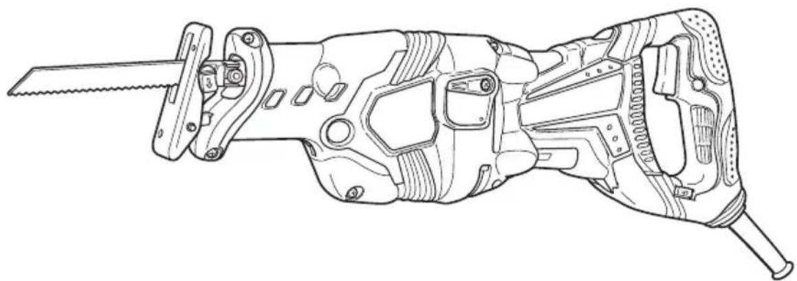
NAME OF PARTS

Fig. 1
SPECIFICATIONS
| Motor Single-Phase, Series Commutator Motor | |
| Power Source Single-Phase, 120 V AC 60 Hz | |
| Current 13 A | |
| Capacity Mild Steel Pipe: O.D. 5" (130 mm)Vinyl Chloride Pipe: O.D. 5" (130 mm)Wood: Depth 5" (130 mm) | |
| No-Load Speed 0 – 3000/min. | |
| Stroke 1-1/4" (32 mm) | |
| Weight (without cord) 9.7 lbs (4.4 kg) | |
ASSEMBLY AND OPERATION
APPLICATIONS
○ Cutting metal and stainless steel pipe.
○ Cutting various lumber.
○ Cutting mild steel, aluminum and copper plate.
○ Cutting synthetic resins, such as phenol resin and vinyl chloride.
PRIOR TO OPERATION
- Power source
Ensure that the power source to be utilized conforms to the power source requirements specified on the product nameplate.
- Power switch
Ensure that the switch is in the OFF position. If the plug is connected to a receptacle while the switch is in the ON position, the power tool will start operating immediately and can cause serious injury.
- Extension cord
When the work area is far away from the power source, use an extension cord of sufficient thickness and rated capacity. The extension cord should be kept as short as practicable.


WARNING:
Damaged cord must be replaced or repaired.
- Check the receptacle
If the receptacle only loosely accepts the plug, the receptacle must be repaired. Contact a licensed electrician to make appropriate repairs.
If such a fautly receptacle is used, it may cause overheating, resulting in a serious hazard.
- Confirming condition of the environment:
Confirm that the work site is placed under appropriate conditions conforming to prescribed precautions.
- Mounting the blade
This unit employs a detachable mechanism that enables mounting and removal of saw blades without the use of a wrench or other tools.
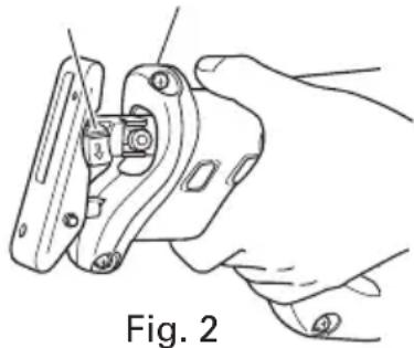
(1) Turn on and off the switching trigger several times so that the lever can jump out of the front cover completely. Thereafter, turn off the switch and unplug the power cord.
(Fig. 2)
Lever
Front cover
natural_image
Line drawing of a hand holding a mechanical clamp or bracket, labeled Fig. 2 (no text or symbols on the diagram itself)CAUTION:
Be absolutely sure to keep the switch turned off and the power cord unplugged to prevent any accident.
(2) Push the lever in the direction of the arrow mark shown in Fig. 3 marked on the lever.

Fig. 3
(3) Insert the saw blade all the way into the small slit of the plunger tip with the lever pushing. You can mount this blade either in the upward or downward direction. (Fig. 4, Fig. 5)


(4) When you release the lever, the spring force will return the lever to the correct position automatically. (Fig. 6)
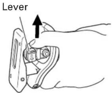
Fig. 6
(5) Pull the back of the saw blade two or three times by hand and check that the blade is securely mounted. When pulling the blade, you will
know it is properly mounted if it clicks and the lever moves slightly. (Fig. 7)
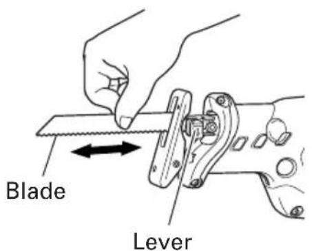
Fig. 7
CAUTION:
When pulling the saw blade, be absolutely sure to pull it from the back. Pulling other parts of the blade will result in an injury.
7. Dismounting the blade
(1) Turn on and off the switching trigger several times so that the lever can jump out of the front cover completely. Thereafter, turn off the switch and unplug the power cord. (Fig. 2)
CAUTION:
Be absolutely sure to keep the switch turned off and the power cord unplugged to prevent any accident.
(2) After you have pushed the lever in the direction of the arrow mark shown in Fig. 3, turn the blade so it faces downward. The blade should fall out by itself. If the blade doesn't fall out, pull it out by hand.
CAUTION:
Never touch the saw blade immediately after use. The metal is hot and can easily burn your skin.
WHEN THE BLADE IS BROKEN
Even when the saw blade is broken and remains inside the small slit of the plunger, it should fall out if you push the lever in the direction of the arrow mark, and face the blade downward. If it doesn't fall out itself, take it out using the procedures explained below.
(1) If a part of the broken saw blade is sticking out of the small slit of the plunger, pull out the protruding part and take the blade out.
(2) If the broken saw blade is hidden inside the small slit, hook the broken blade using a tip of another saw blade and take it out. (Fig. 8)

Slit of plunger
Fig. 8
MAINTENANCE AND INSPECTION OF SAW BLADE MOUNT
(1) After use, blow away sawdust, earth, sand, moisture, etc., with air or brush them away with a brush, etc., to ensure that the blade mount can function smoothly.
(2) As shown in Fig. 9, carry out lubrication around the blade holder on a periodic basis by use of cutting fluid, etc.

Fig. 9
NOTE:
Continued use of the tool without cleaning and lubricating the area where the saw blade is installed can result in some slack movement of the lever due to accumulated sawdust and chips. Under the circumstances, pull a rubber cap provided on the lever in the direction of an arrow mark as shown in Fig. 10 and remove the rubber cap from the lever. Then, clean up the inside of the blade holder with air and the like and carry out sufficient lubrication.
The rubber cap can be fitted on if it is pressed firmly onto the lever. At this time, make certain that there exists no clearance between the blade holder and the rubber cap, and furthermore ensure that the saw-blade-installed area can function smoothly.

Rubber cap
Fig. 10

CAUTION:
Do not use any saw blade with a worn-out blade hole. Otherwise, the saw blade can come off, resulting in personal injury. (Fig. 11)
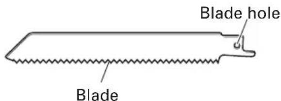
Fig. 11
8. Adjusting the base
This unit employs a mechanism that can adjust the base mounting position in three
stages without the use of a wrench or other tools.
(1) Press a pushbutton. When you do this, a base lever will jump out to prepare the base for adjustment (Fig. 12)

Fig. 12
(2) Push up the base tip and jog the base back and forth. (Fig. 13)
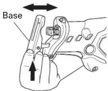
Fig. 13
(3) You can adjust the base position in three stages. Move the base at an interval of about 15 mm, find the position where the base hooks, and press in the base lever with your fingers. The base is secured when you hear the clicking sound. (Fig. 14)

Fig. 14
- Adjusting the blade reciprocating speed
This unit has a built-in electronic control circuit that makes it possible to adjust the variable speed of the saw blade either both by pulling a switching trigger or turning a dial. (Fig. 15)

Fig. 15
(1) If you pull the trigger further in, the speed of the blade accelerates. Begin cutting at a low speed to ensure the accuracy of your target cut position. Once you've obtained a sufficient cutting depth, increase the cutting speed.
(2) On the dial scale, "5" is the maximum speed and "1" the minimum. The high speed is generally suitable for soft materials such as wood, and the low speed is suitable for hard materials such as metal. We recommend that you use the following as a rough guide in selecting the suitable speed for the materials you are cutting.
| Example of materials Recommended to be cut dial scale | |
| Mild steel pipes / cast-iron tubes / 2 – 4 L-shaped angle steel | |
| Wood / wood with nails driven in | 5 |
| Stainless steel 1 – 3 | |
| Aluminum / brass / copper 2 – 4 | |
| Plaster board 4 – 5 | |
| Plastic / fiber board 1 – 3 |
CAUTION:
When cutting at low speed (scale of 1 – 2), never cut a wooden board more than 25/64" (10 mm) thick or a mild steel plate more than 5/64" (2 mm) thick. The load
on the motor can result in overheating and damage.
Although this unit employs a powerful motor, prolonged use at a low speed will increase the load unduly and may lead to overheating. Properly adjust the saw blade to allow steady, smooth cutting operation, avoiding any unreasonable use such as sudden stops during cutting operation.
- Adjusting the swing cutting operation Two cutting systems can be selected with this unit. The first is straight cutting, in which the saw blade is moved linearly, and the second is the swing cutting, in which the saw blade is swung like a pendulum. (Fig. 16, Fig. 17)
(1) Straight cutting
You can perform straight cutting by setting the change lever widthwise. Straight cutting should normally be performed when cutting hard materials such as metal, etc. (Fig. 16)
Straight cutting

Fig. 16
(2) Swing cutting
You can perform swing cutting by setting the change lever lengthways.
Swing cutting should normally be performed when cutting soft materials such as wood, etc.
Swing cutting is efficient since the saw blade forcibly bites into the material. (Fig. 17)
Change lever
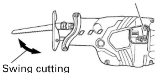
Fig. 17
CAUTION:
○ Even for soft materials, you should perform straight cutting if you wish to make curved or clean cuts.
○ Dust and dirt accumulated on the change lever section can degrade the function of the change lever. Periodically clean the change lever section.
When performing swing cutting, use a saw with straight blade. If a saw with curved blade is used, the saw blade may be broken or the unit may be damaged.
HOW TO USE THE RECIPROCATING SAW
CAUTION:
○ Avoid carrying it plugged to the outlet with your finger on the switch. A sudden startup can result in an unexpected injury.
○ Be careful not to let sawdust, earth, moisture, etc., enter the inside of the machine through the plunger section during operation. If sawdust and the like accumulate in the plunger section, always clean it before use.
○ Do not remove the front cover (refer to Fig. 2).
Hold firmly the front cover by hand to operate.
But, do not extend your hand or finger beyond the flange (see Fig.18) of front cover to avoid an injury.
○ During use, press the base against the material while cutting.
Vibration can damage the saw blade if the base is not pressed firmly against the workpiece.
Furthermore, a tip of the saw blade can sometimes contact the inner wall of the pipe, damaging the saw blade.
○ Select a saw blade of the most appropriate length. Ideally, the length protruding from the base of the saw blade after subtracting the stroke should be larger than the material (see Fig. 18 and Fig. 19).

Fig. 18

Fig. 19
If you cut a large pipe, large block of wood, etc., that exceeds the cutting capacity of a blade; there is a risk that the blade may contact with the inner wall of the pipe, wood, etc., resulting in damage. (Fig. 20, Fig. 21)

natural_image
Illustration of a hand using a tool to cut a circular object, with no visible text or symbolsFig. 20

natural_image
Illustration of a hand using a tool to cut wood grain with a cutting board (no text or symbols)Fig. 21
To maximize cutting efficiency for the materials you are using and working conditions, adjust the speed of the saw blade and the switching to swing cutting.
- Cutting metallic materials
CAUTION:
○ Press the base firmly against the workpiece.
Never apply any unreasonable force to the saw blade when cutting. Doing so can easily break the blade.
(1) Fasten a workpiece firmly before operation. (Fig.22)

natural_image
Technical line drawing of a hand using a tool to adjust or install a mechanical component (no text or symbols present)Fig. 22
(2) When cutting metallic materials, use proper machine oil (turbine oil, etc.). When not using liquid machine oil, apply grease over the workpiece.
CAUTION:
The service life of the saw blade will be drastically shortened if you don't use machine oil.
(3) Use the dial to adjust the speed of the saw blade to suit your working conditions and materials.
(4) You can cut smoothly if you set the change lever position to straight cutting (Fig. 16).
2. Cutting lumber
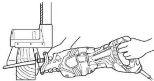
(1) When cutting lumber, make sure that the workpiece is fastened firmly before beginning. (Fig. 23)
natural_image
Technical line drawing of a hand using a tool to adjust or install a mechanical component (no text or symbols present)Fig. 23
(2) You can cut efficiently if the speed of the saw blade is set to dial scale "5".
(3) You can cut efficiently if the change lever position is set to swing cutting (Fig. 17). Alternatively, you can cut cleanly if the change lever position is set to straight cutting (Fig. 16).
CAUTION:
Never apply any unreasonable force to the saw blade when cutting. Also remember to press the base against the lumber firmly.
3. Sawing curved lines
We recommend that you use the BIMETAL blade mentioned in Page 18 for the saw blade since it is tough and hardly breaks.
CAUTION:
Delay the feed speed when cutting the material into small circular arcs. An unreasonably fast feed may break the blade.
4. Plunge cutting
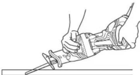
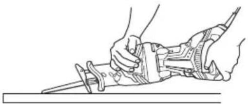
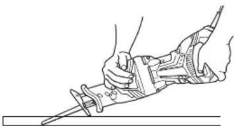
With this tool, you can perform pocket cutting on plywood panels and thin board materials. You can carry out pocket cutting quite easily with the saw blade installed in reverse as illustrated in Fig. 25, Fig. 27, and Fig. 29. Use the saw blade that is as short and thick as possible. We recommend for this purpose that you use BI-METAL Blade No. 132 mentioned in Page 18. Be sure to use caution during the cutting operation and observe the following procedures.
(1) Press the lower part (or the upper part) of the base against the material. Pull the switch trigger while keeping the tip of the saw blade apart from the material. (Fig. 24, Fig. 25)

natural_image
Line drawing of hands using a tool to cut a surface (no text or symbols present)Fig. 24

natural_image
Line drawing of hands using a sawdriver to cut a tool (no text or symbols present)Fig. 25
(2) Raise the handle slowly and cut in with the saw blade little by little. (Fig. 26, Fig. 27)

natural_image
Line drawing of a hand using a tool to cut or install a mechanical component (no text or symbols present)Fig. 26
natural_image
Line drawing of hands using a tool to cut or install a component (no text or symbols present)Fig. 27
(3) Hold the body firmly until the saw blade completely cuts into the material. (Fig. 28, Fig. 29)

natural_image
Illustration of a hand using a tool to lift a screwdriver (no text or symbols present)Fig. 28

natural_image
Line drawing of a hand using a tool to lift a cylindrical object, no text or symbols presentFig. 29
CAUTION:
○ Avoid plunge cutting for metallic materials. This can easily damage the blade.
Never pull the switch trigger while the tip of the saw blade tip is pressed against the material. If you do so, the blade can easily be damaged when it collides with the material.
○ Make absolutely sure that you cut slowly while holding the body firmly. If you apply any unreasonable force to the saw blade during the cutting operation, the blade can easily be damaged.
MAINTENANCE AND INSPECTION
⚠ WARNING: Be sure to switch power OFF and disconnect the plug from the receptacle during maintenance and inspection.
- Inspecting the blade
Continued use of a dull or damaged blade will result in reduced cutting efficiency and may cause overloading of the motor. Replace the blade with a new one as soon as excessive abrasion is noted. - Inspecting the mounting screws
Regularly inspect all mounting screws and ensure that they are properly tightened. Should any of the screws be loosened, retighten them immediately.
WARNING: Using this reciprocating saw with loosen screws is extremely dangerous.
-
Maintenance of the motor The motor unit winding is the very "heart" of the power tool. Exercise due care to ensure the winding does not become damaged and/or wet with oil or water.
-
Inspecting the carbon brushes (Fig. 30) The Motor employs carbon brushes which are consumable parts. When they become worn to or near the "wear limit", it could result in motor trouble. When an auto-stop carbon brush is equipped, the motor will stop automatically. At that time, replace both carbon brushes with new ones which have the same carbon brush Numbers shown in the figure. In addition, always keep carbon brushes clean and ensure that they slide freely within the brush holders.

Fig. 30
NOTE: Use HITACHI carbon brush No. 43 indicated in Fig. 30.
-
Replacing carbon brushes Disassemble the brush caps with a slotted-head screwdriver. The carbon brushes can then be easily removed.
-
Service and repairs All quality power tools will eventually require servicing or replacement of parts because of wear from normal use. To assure that only authorized replacement parts will be used, all service and repairs must be performed by a HITACHI AUTHORIZED SERVICE CENTER, ONLY.
-
Service parts list
CAUTION:
Repair, modification and inspection of Hitachi Power Tools must be carried out by an Hitachi Authorized Service Center. This Parts List will be helpful if presented with the tool to the Hitachi Authorized Service Center when requesting repair or other maintenance. In the operation and maintenance of power tools, the safety regulations and standards prescribed in each country must be observed.
MODIFICATIONS:
Hitachi Power Tools are constantly being improved and modified to incorporate the latest technological advancements. Accordingly, some parts may be changed without prior notice.
ACCESSORIES

WARNING:
ALWAYS use Only authorized HITACHI replacement parts and accessories. NEVER use replacement parts or accessories which are not intended for use with this tool. Contact HITACHI if you are not sure whether it is safe to use a particular replacement part or accessory with your tool.
The use of any other attachment or accessory can be dangerous and could cause injury or mechanical damage.
NOTE: Accessories are subject to change without any obligation on the part of the HITACHI.
STANDARD ACCESSORIES
(1) Blade (Code No. 725362)....1
(2) Case (Code No. 321142) .... 1
OPTIONAL ACCESSORIES......sold separately
| TYPE LENGTH | WIDTH TPI | MATERIAL | CODE NO. | BLADES /POUCH | ||
| WOOD CUTTING 9" (228 mm) | 6" (152 mm) 3/4" (18 mm) 6 HCS 725300 5 | |||||
| 8 mm) 3/4" (18 mm) 5 HCS 725301 5 | ||||||
| 12" (305 mm) 3/4" (18 mm) 6 HCS 725302 5 | ||||||
| WOOD CUTTINGNAIL-EMBEDED | 6" (152 mm) 3/4" (18 mm) 6 BI-METAL 725 310 5 | |||||
| 6" (152 mm) 3/4" (18 mm) 6 BI-METAL 725 311 5 | ||||||
| 6" (152 mm) 5/8" (16 mm) 6 BI-METAL 725 312 5 | ||||||
| 9" (228 mm) 3/4" (18 mm) 6 BI-METAL 725 313 5 | ||||||
| 12" (305 mm) 3/4" (18 mm) 6 BI-METAL 725 314 5 | ||||||
| METAL CUTTING | 6" (152 mm) 3/4" (18 mm) 10 BI-METAL 725 320 5 | |||||
| 9" (228 mm) 3/4" (18 mm) 10 BI-METAL 725 321 5 | ||||||
| 6" (152 mm) 3/4" (18 mm) 14 BI-METAL 725 322 5 | ||||||
| 9" (228 mm) 3/4" (18 mm) 14 BI-METAL 725 323 5 | ||||||
| 6" (152 mm) 3/4" (18 mm) 18 BI-METAL 725 324 5 | ||||||
| 9" (228 mm) 3/4" (18 mm) 18 BI-METAL 725 326 5 | ||||||
| 6" (152 mm) 3/4" (18 mm) 24 BI-METAL 725 325 5 | ||||||
| 9" (228 mm) 3/4" (18 mm) 24 BI-METAL 725 327 5 | ||||||
| ALL PURPOSE | 6" (152 mm) 3/4" (18 mm) 10//14 BI-METAL 725330 5 | |||||
| 9" (228 mm) | 3/4" (18 mm) | 10//14 | BI-METAL | 725331 | 5 | |
| 12" (305 mm) 3/4" (18 mm) 10//14 BI-METAL 725332 5 | ||||||
| CARBIDE GRIT | 9" (228 mm) | 3/4" (18 mm) | GRIT | — | 725340 | 3 |
| DEMOLITION | 9" (228 mm) 7/8" (22 mm) 6 BI-METAL 725 350 3 | |||||
| 9" (228 mm) 7/8" (22 mm) 9 BI-METAL 725 351 3 | ||||||
| NEW WOOD | 6" (152 mm) | 3/4" (18 mm) | PROG. | BI-METAL | 725360 | 5 |
| NEW METAL | 6" (152 mm) | 3/4" (18 mm) | PROG. | BI-METAL | 725361 | 5 |
| NEW ALL PURPOSE | 8" (203 mm) | 3/4" (18 mm) | PROG. | BI-METAL | 725362 | 5 |
PROG.: NEW PROGRESSIVE TOOTH HCS: HIGHSPEED CARBON STEEL
NOTE: Specifications are subject to change without any obligation on the part of the HITACHI.
INFORMATIONS IMPORTANTES DE SÉCURITÉ
natural_image
Hand holding a mechanical clamp or bracket with a black arrow pointing to the handle (no text or symbols present)Fig. 3
natural_image
Line drawing of a hand holding a tool with a black arrow indicating direction (no text or symbols)natural_image
Illustration of hands using a tool to cut a circular object with a diagonal band (no text or symbols)Fig. 20

natural_image
Illustration of hands using a tool to cut wood or wood fragments, no text or symbols presentFig. 21
natural_image
Line drawing of hands using a tool to adjust or install a mechanical component (no text or symbols present)Fig. 22
natural_image
Technical line drawing of a hand using a tool to cut or adjust a mechanical component (no text or symbols present)Fig. 23
natural_image
Line drawing of hands using a sawtooth tool to cut a wooden plank (no text or symbols present)Fig. 24
natural_image
Line drawing of hands using a power tool to cut a saw (no text or symbols present)Fig. 25
natural_image
Line drawing of a hand using a tool to lift a mechanical component (no text or symbols)Fig. 26

natural_image
Line drawing of hands using a tool to cut or install a component (no text or symbols present)Fig. 27
natural_image
Line drawing of a hand holding a tool over a flat surface, no text or symbols presentFig. 28

natural_image
Line drawing of a hand holding a tool with a screwdriver inserted (no text or symbols)Fig. 29
ATTENTION:
natural_image
Illustration of a hand using a tool to cut a saw (no text or symbols present)Ranura del émbolo
Fig. 5
natural_image
Technical illustration of a mechanical tool interacting with a circular component (no text or symbols visible)Fig. 20

natural_image
Illustration of a hand using scissors to cut wood grain, no text or symbols presentFig. 21
natural_image
Technical line drawing of hands operating a mechanical tool or clamp (no text or symbols present)Fig. 22
natural_image
Illustration of hands using a tool to cut wood or wood clamps, no text or symbols presentFig. 23
natural_image
Line drawing of hands using a tool to cut a saw (no text or symbols present)Fig. 24

natural_image
Line drawing of hands using a power tool to cut a component (no text or symbols present)Fig. 25
natural_image
Line drawing of a hand using a tool to cut a mechanical component (no text or symbols present)Fig. 26
natural_image
Line drawing of hands using a tool to cut or install a mechanical component (no text or symbols present)Fig. 27
natural_image
Line drawing of a hand using a tool to tighten or adjust a mechanical component (no text or symbols present)Fig. 28

natural_image
Line drawing of a hand holding a tool with a pen, no text or symbols presentFig. 29
PRECAUCION
natural_image
Line drawing of a quill pen in an inkwell (no text or symbols)
natural_image
Line drawing of a quill pen with inkwell (no text or symbols)
natural_image
Line drawing of a quill pen in an inkwell (no text or symbols)WARNING:
Some dust created by power sanding, sawing, grinding, drilling, and other construction activities contains chemicals known to the State of California to cause cancer, birth defects or other reproductive harm. Some examples of these chemicals are:
- Lead from lead-based paints,
- Crystalline silica from bricks and cement and other masonry products, and
- Arsenic and chromium from chemically-treated lumber.
Your risk from these exposures varies, depending on how often you do this type of work. To reduce your exposure to these chemicals: work in a well ventilated area, and work with approved safety equipment, such as those dust masks that are specially designed to filter out microscopic particles.
AVERTISSEMENT:
Minato-ku, Tokyo 108-6020, Japan
Distributed by

Hitachi Koki U.S.A., Ltd.
3950 Steve Reynolds Blvd.
Norcross, GA 30093

Hitachi Koki Canada Co.
6395 Kestrel Road
Mississauga ON L5T 1Z5
609
Code No. C99157161
Printed in China

- INSTRUCTION MANUAL AND SAFETY INSTRUCTIONS
- WARNING
- MODE D'EMPLOI ET INSTRUCTIONS DE SECURITE
- AVERTISSEMENT
- TABLE DES MATIERES
- Français
- ÍNDICE
- Español
- IMPORTANT SAFETY INFORMATION
- MEANINGS OF SIGNAL WORDS
- SAFETY
- GENERAL SAFETY RULES
- ⚠ WARNING: Read all instructions
- SAVE THESE INSTRUCTIONS
- 1) Work area safety
- 2) Electrical Safety
- 3) Personal safety
- -WARNING-
- SPECIFIC SAFETY RULES AND SYMBOLS
- SAVE THESE INSTRUCTIONS AND
- MAKE THEM AVAILABLE TO
- OTHER USERS
- AND
- OWNERS OF THIS TOOL!
- FUNCTIONAL DESCRIPTION
- NAME OF PARTS
- ASSEMBLY AND OPERATION
- APPLICATIONS
- PRIOR TO OPERATION
- WARNING:
- CAUTION:
- Dismounting the blade
- WHEN THE BLADE IS BROKEN
- MAINTENANCE AND INSPECTION OF SAW BLADE MOUNT
- NOTE:
- Adjusting the base
- HOW TO USE THE RECIPROCATING SAW
- Cutting lumber
- Sawing curved lines
- Plunge cutting
- MAINTENANCE AND INSPECTION
- ⚠ WARNING: Be sure to switch power OFF and disconnect the plug from the receptacle during maintenance and inspection.
- WARNING: Using this reciprocating saw with loosen screws is extremely dangerous.
- MODIFICATIONS:
- ACCESSORIES
- STANDARD ACCESSORIES
- INFORMATIONS IMPORTANTES DE SÉCURITÉ
- ATTENTION:
- PRECAUCION
- AVERTISSEMENT:
- Hitachi Koki U.S.A., Ltd.
- Hitachi Koki Canada Co.
Brand : HITACHI
Model : CR13VBY
Category : Saw