GHE 450 - Plane STIHL - Free user manual and instructions
Find the device manual for free GHE 450 STIHL in PDF.
| Product type | Planer (shredder) |
| Brand | STIHL |
| Model | GHE 450 |
| Dimensions (L x W x H) | 108 cm x 51 cm x 137 cm |
| Weight | 52 kg |
| Electrical supply | 400 V / 3~ / 50 Hz |
| Power consumption | 3800 W |
| Fuse protection | 10 A |
| Maximum branch diameter | 55 mm |
| Cutting system | Multi-Cut 450 |
| Rated engine speed | 2800 rpm |
| Wheel diameter | 250 mm |
| Guaranteed sound power level | 108 dB(A) |
| Sound pressure level | 95 dB(A) |
| Protection class | I |
| Protection type | IPX4 (splash-proof) |
| Safety devices | Restart lock, funnel lock, deceleration brake |
| Maintenance | Cleaning after each use, sharpening/rotating blades, checking wear limits |
| Common spare parts | Blade discs, blades, counter-blade (references in manual) |
| Warranty | See manufacturer's terms |
Frequently Asked Questions - GHE 450 STIHL
User questions about GHE 450 STIHL
0 question about this device. Answer the ones you know or ask your own.
Ask a new question about this device
Download the instructions for your Plane in PDF format for free! Find your manual GHE 450 - STIHL and take your electronic device back in hand. On this page are published all the documents necessary for the use of your device. GHE 450 by STIHL.
USER MANUAL GHE 450 STIHL
natural_image
Exterior view of a STIHL industrial cleaning brush unit (no text or symbols visible on body)GHE 420.0 GHE 450.0
text_image
Technical diagram of a mechanical device with numbered parts labeled 1 through 8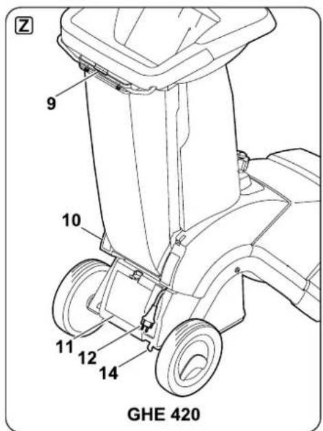
text_image
Z 9 10 11 12 14 GHE 420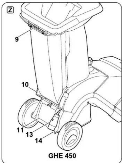
text_image
Z 9 10 11 13 14 GHE 450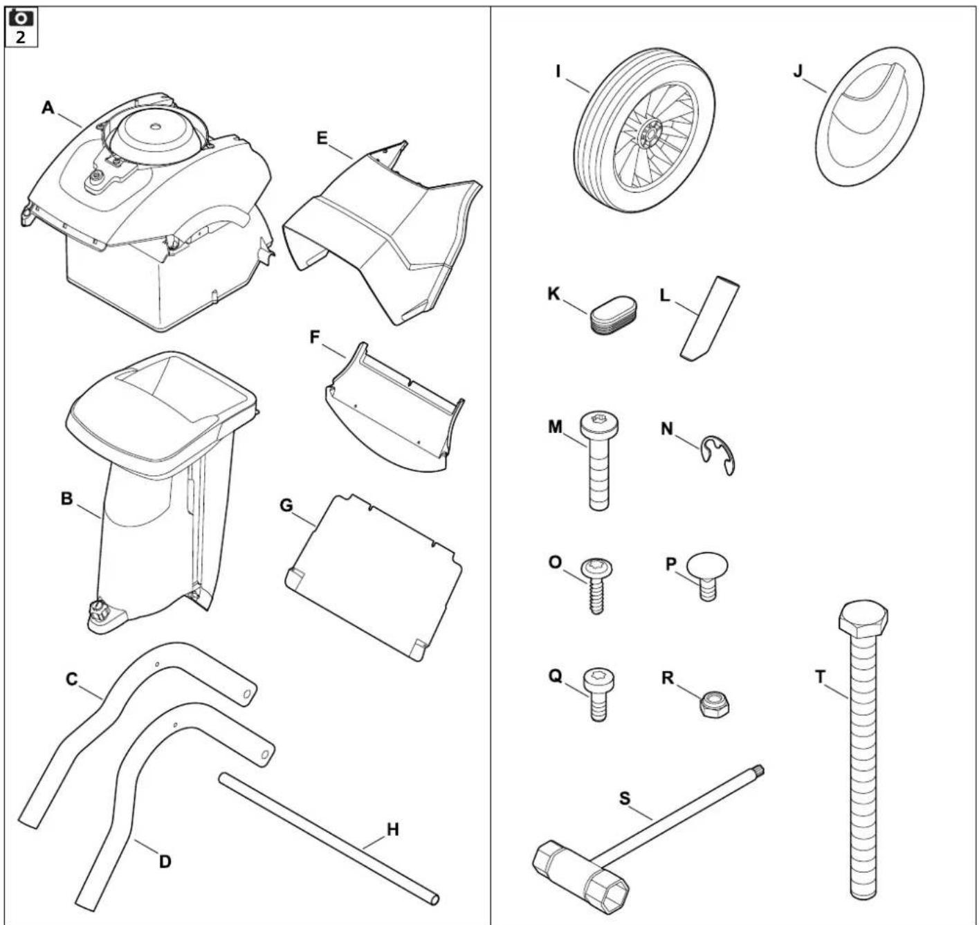
text_image
5 M 10 - 12 Nm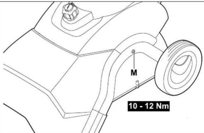
text_image
M 10 - 12 Nm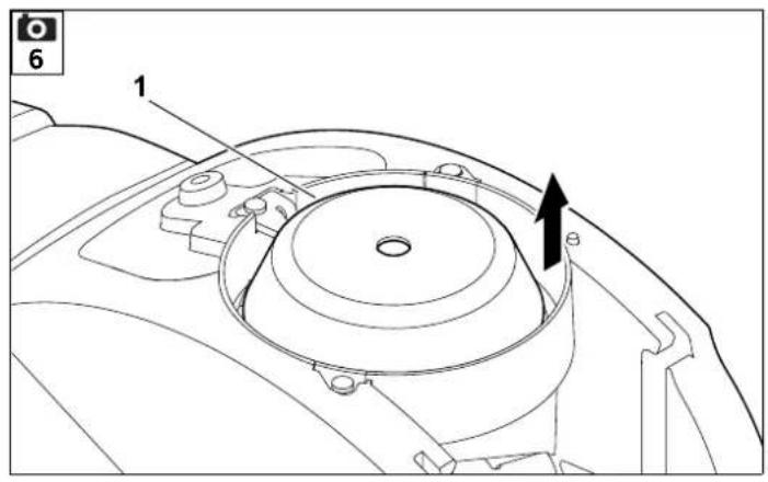
text_image
6 1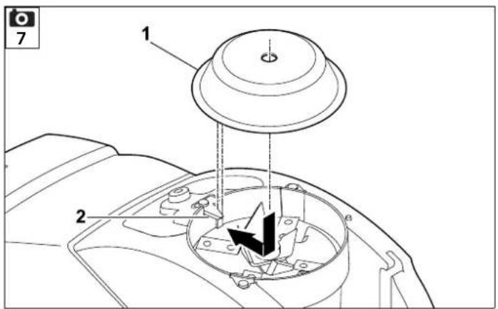
text_image
1 2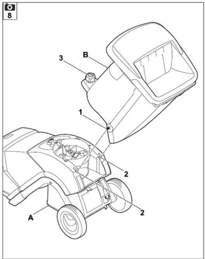
text_image
8 3 B 1 2 A 2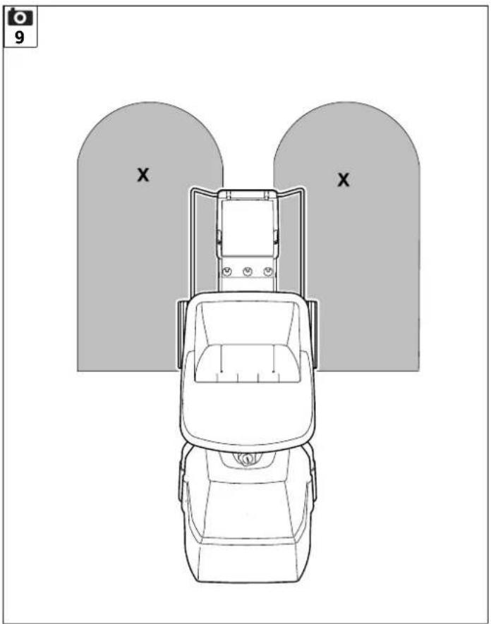
natural_image
Top-down line drawing of a car with two large arches labeled 'X' (no text or symbols on the car itself)0478 201 9916 A
text_image
10 ✓ O.K. ×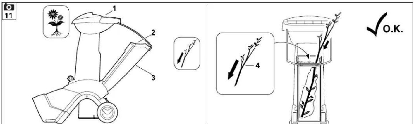
text_image
11 1 2 3 4 O.K.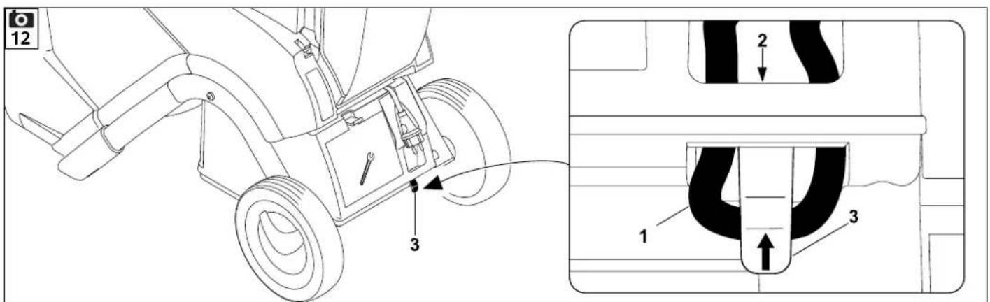
text_image
12 3 1 2 3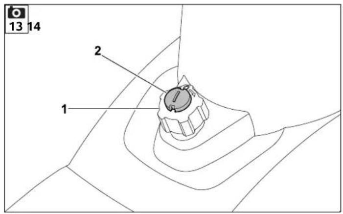
text_image
13 14 2 1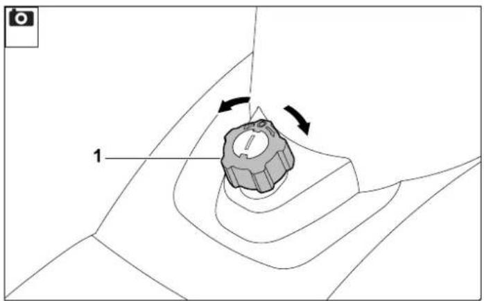
natural_image
Technical diagram of a mechanical component with curved surfaces and directional arrows, no readable text or symbols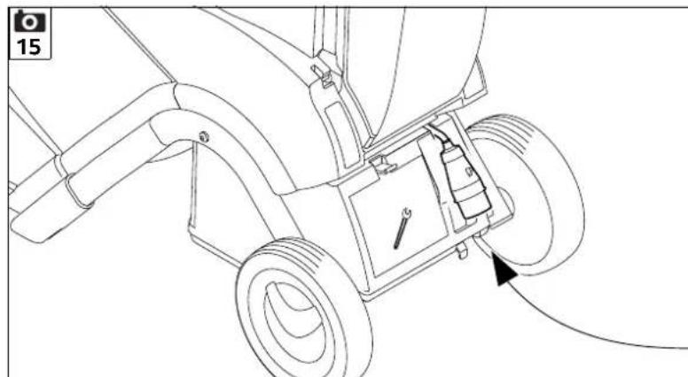
natural_image
Technical line drawing of a mechanical assembly with gears and a wrench, no text or symbols present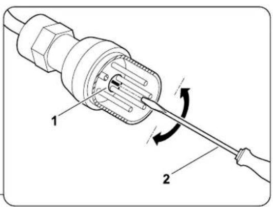
text_image
Technical diagram of a plug with labeled parts and directional arrows indicating tool movement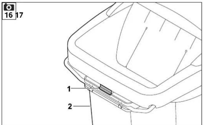
text_image
16 17 1 2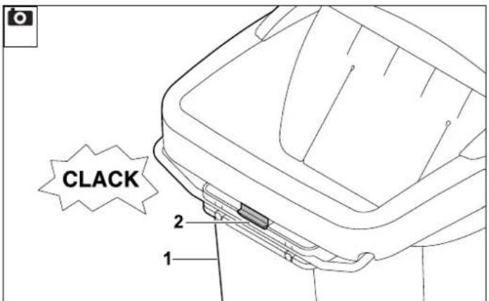
text_image
CLACK 2 1
text_image
18 1 2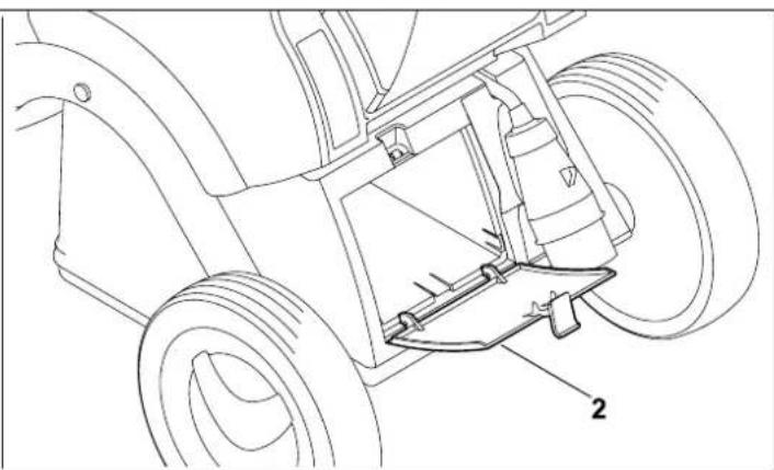
natural_image
Technical line drawing of a mechanical assembly with two wheels and a central mounting bracket (no text or symbols)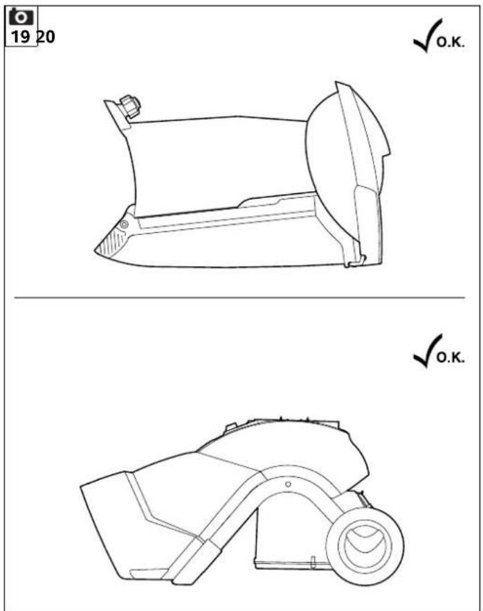
text_image
19 20 ✓ O.K. ✓ O.K.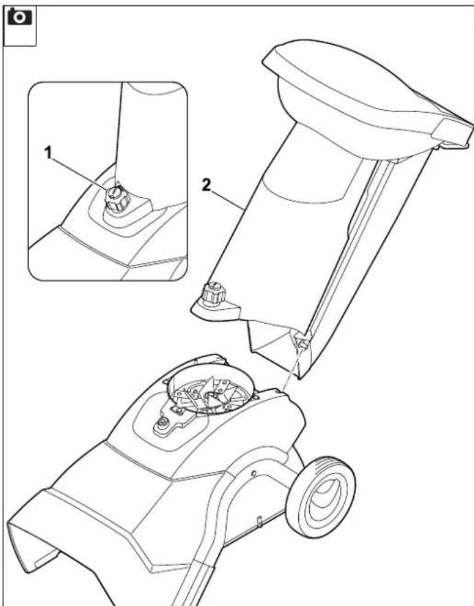
text_image
Technical diagram of a mechanical device with labeled parts and an inset view showing a close-up detail.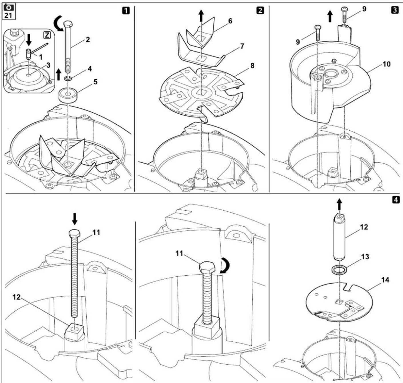
text_image
22 8 33 - 37 Nm A Z 15 16 14 13 12 11 10 36 - 44 Nm 9 6 1 2 1 3 4 5 7 8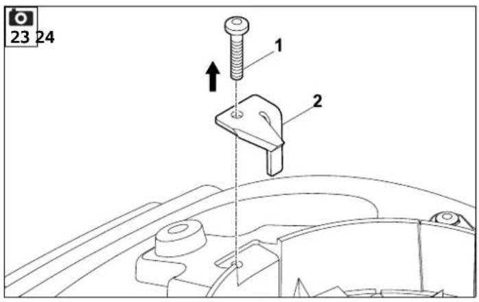
text_image
23 24 1 2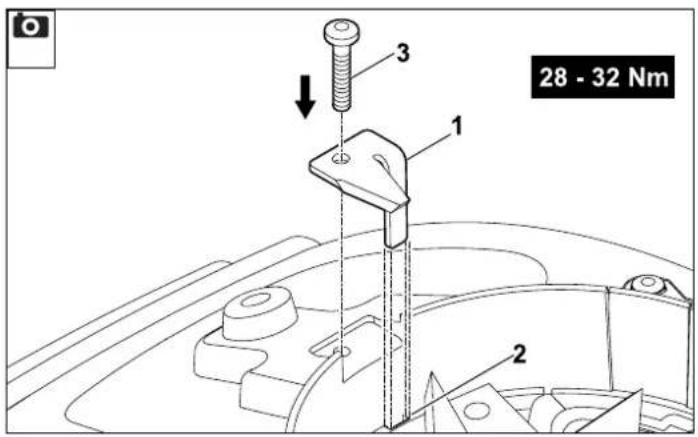
text_image
28 - 32 Nm 1 2 3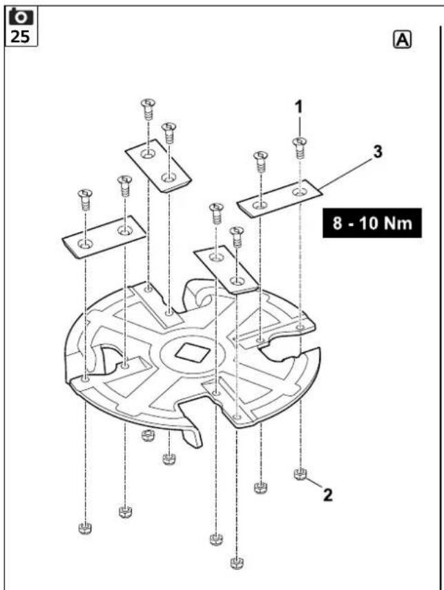
text_image
25 A 1 3 8 - 10 Nm 2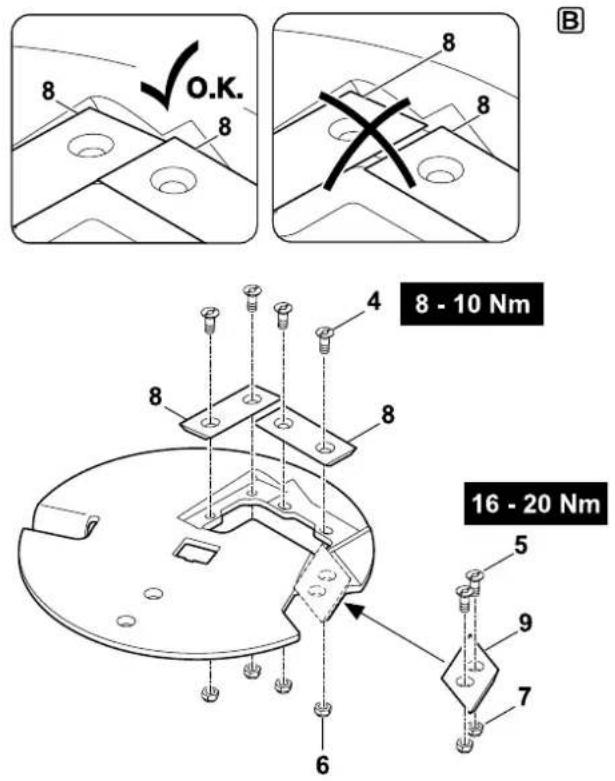
text_image
8 O.K. 8 8 8 8 - 10 Nm 4 8 8 8 5 9 7 6 16 - 20 Nm26
natural_image
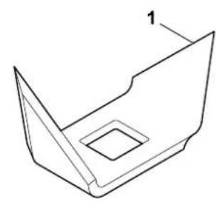
Technical line drawing of a 3D mechanical part with a square hole and angular cutout (no text or symbols)2x
natural_image
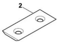
Simple line drawing of a rectangular plate with two circular holes, labeled with number 2 (no text or symbols on the plate itself)6x
natural_image
Simple line drawing of a flat plate with two circular holes, labeled with number 3 (no text or symbols on the plate itself)1x
1x
text_image
A = 39 mm 1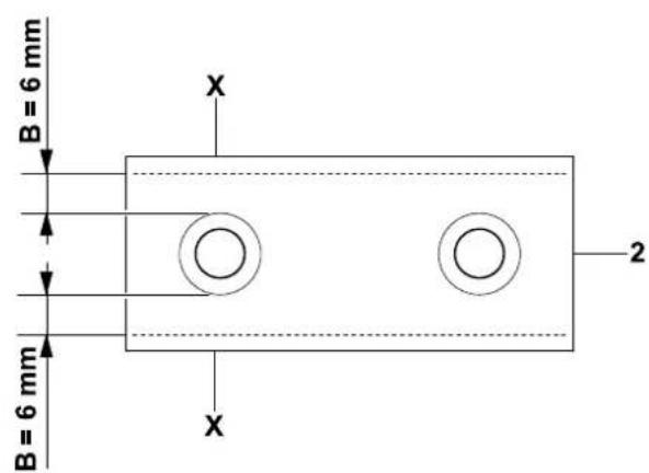
text_image
B = 6 mm B = 6 mm X 2 X3
text_image
C = 7 mm 3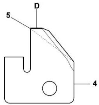
text_image
5 D 45


text_image
2.0 2.0
text_image
U U 2,0 U U 2,0
text_image
2.0 2.0
text_image
2.0 2.0
text_image
2,0 2,0
text_image
2.0 2.0
text_image
2.0 2.0
text_image
2.0 2.0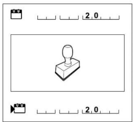
text_image
2.0 2.0Thank you for choosing STIHL. We develop and manufacture our quality products to meet our customers' requirements. The products are designed for reliability even under extreme conditions.
STIHL also stands for premium service quality. Our specialist dealers guarantee competent advice and instruction as well as comprehensive service support.
We thank you for your confidence in us and hope you will enjoy working with your STIHL product.

Dr. Nikolas Stihl
IMPORTANT: READ BEFORE USE AND KEEP IN A SAFE PLACE.
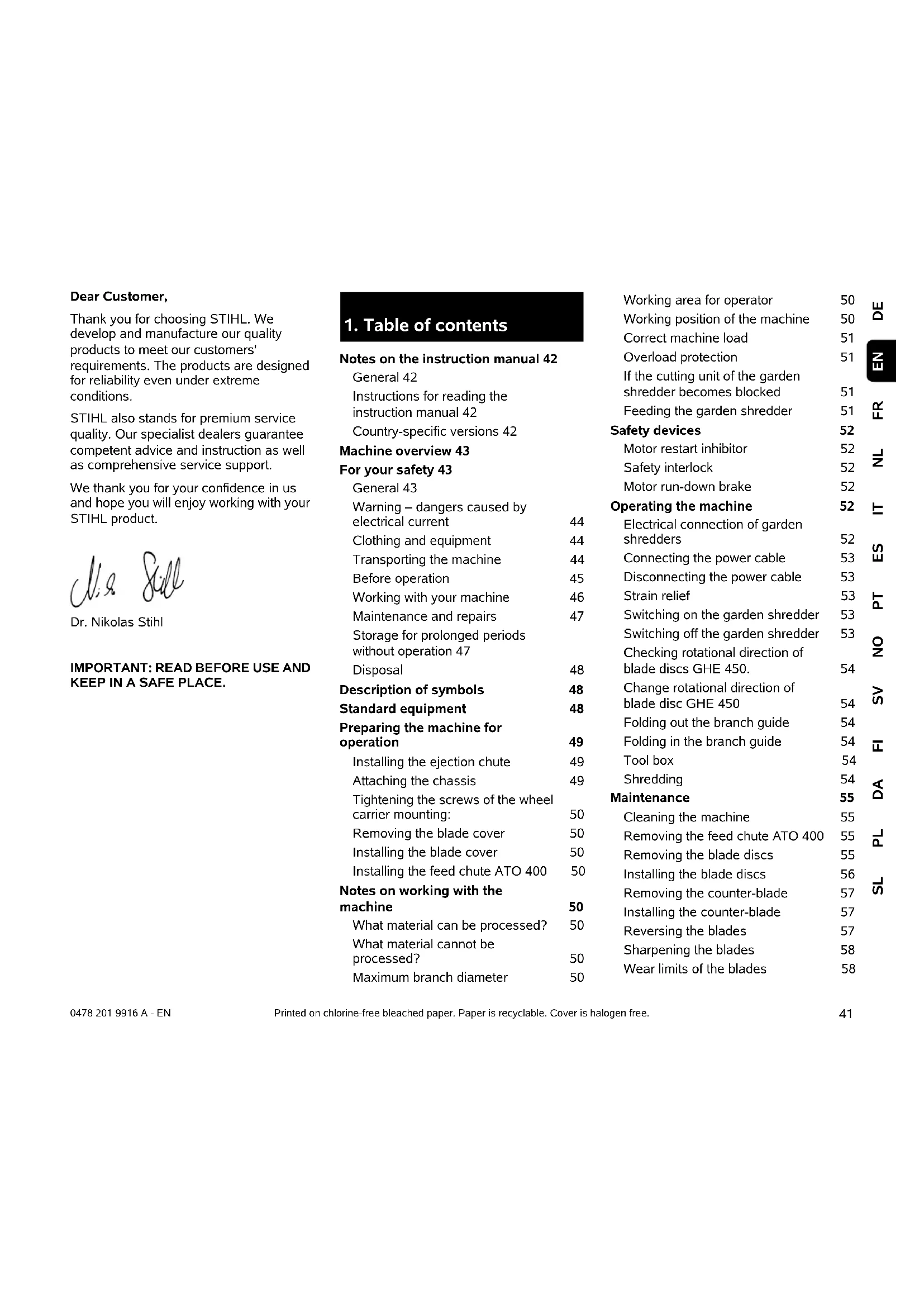
1. Table of contents
Notes on the instruction manual 42
General 42
Instructions for reading the instruction manual 42
Country-specific versions 42
Machine overview 43
For your safety 43
General 43
Warning – dangers caused by electrical current 44
Clothing and equipment 44
Transporting the machine 44
Before operation 45
Working with your machine 46
Maintenance and repairs 47
Storage for prolonged periods without operation 47
Disposal 48
Description of symbols 48
Standard equipment 48
Preparing the machine for operation 49
Installing the ejection chute 49
Attaching the chassis 49
Tightening the screws of the wheel carrier mounting: 50
Removing the blade cover 50
Installing the blade cover 50
Installing the feed chute ATO 400 50
Notes on working with the machine 50
What material can be processed? 50
What material cannot be processed? 50
Maximum branch diameter 50
Working area for operator 50
Working position of the machine 50
Correct machine load 51
Overload protection 51
If the cutting unit of the garden shredder becomes blocked 51
Feeding the garden shredder 51
Safety devices 52
Motor restart inhibitor 52
Safety interlock 52
Motor run-down brake 52
Operating the machine 52
Electrical connection of garden shredders 52
Connecting the power cable 53
Disconnecting the power cable 53
Strain relief 53
Switching on the garden shredder 53
Switching off the garden shredder 53
Checking rotational direction of blade discs GHE 450. 54
Change rotational direction of blade disc GHE 450 54
Folding out the branch guide 54
Folding in the branch guide 54
Tool box 54
Shredding 54
Maintenance 55
Cleaning the machine 55
Removing the feed chute ATO 400 55
Removing the blade discs 55
Installing the blade discs 56
Removing the counter-blade 57
Installing the counter-blade 57
Reversing the blades 57
Sharpening the blades 58
Wear limits of the blades 58
Electric motor and wheels 59
Service intervals 59
Storage and winter break 59
Transport 59
Minimising wear and preventing damage 60
Standard spare parts 61
Environmental protection 61
Disposal 61
EU - Declaration of conformity 61
STIHL GHE 420.0, GHE 450.0
Garden Shredder 61
Technical specifications 62
REACH 62
Troubleshooting 63
Service schedule 63
Handover confirmation 63
Service confirmation 63
2. Notes on the instruction manual
2.1 General
This instruction manual constitutes original manufacturer's instructions in the sense of EC Directive 2006/42/EC.
STIHL is continually striving to further develop its range of products; we therefore reserve the right to make alterations to the form, technical specifications and equipment level of our standard equipment.
For this reason, the information and illustrations in this manual are subject to alterations.
This instruction manual may describe models that are not available in all countries.
This instruction manual is protected by copyright. All rights reserved, especially the right of reproduction, translation and processing using electronic systems.
2.2 Instructions for reading the instruction manual
Illustrations and texts describe specific operating steps.
All symbols which are affixed to the machine are explained in this instruction manual.
Viewing direction:
Viewing direction when left and right are used in the instruction manual: the user is standing behind the machine (working position).
Section reference:
References to relevant sections and subsections for further descriptions are made using arrows. The following example shows a reference to a section: (⇔ 3.)
Designation of text passages:
The instructions described can be identified as in the following examples.
Operating steps which require intervention on the part of the user:
- Release screw (1) using a screwdriver, operate lever (2)...
General lists:
– Use of the product for sporting or competitive events
Texts with added significance:
Text passages with added significance are identified using the symbols described below in order to especially emphasise them in the instruction manual:

Danger
Risk of accident and severe injury to persons. A certain type of behaviour is necessary or must be avoided.

Warning
Risk of injury to persons. A certain type of behaviour prevents possible or probable injuries.

Caution
Minor injuries or material damage can be prevented by a certain type of behaviour.

Note
Information for better use of the machine and in order to avoid possible operating errors.
Texts relating to illustrations:
Illustrations relating to use of the machine can be found in the front of this instruction manual.
The camera symbol serves to link the figures on the illustration pages with the corresponding text passages in the instruction manual.

2.3 Country-specific versions
STIHL supplies machines with different plugs and switches, depending on the country of sale.
Machines with European plugs are shown in the illustrations. Machines with other types of plug are connected to the mains in a similar way.
3. Machine overview

1 Feed chute ATO 400
2 On / Off switch
3 Basic unit
4 Ejection chute
5 Wheel carrier
6 Wheel
7 Branch guide
8 Transport handle
9 Branch guide lock
10 Rating plate with machine number
11 Tool box
12 Mains plug GHE 420
13 Mains plug GHE 450
14 Strain relief
4. For your safety
4.1 General

These safety regulations must be observed when working with the machine.

Read the entire instruction manual before using the machine for the first time. Keep the instruction manual in a safe
place for future reference.
These safety precautions are essential for your safety, however the list is not exhaustive. Always use the machine in a reasonable and responsible manner and
be aware that the user is responsible for accidents involving third parties or their property.
Make sure that you are familiar with the controls and use of the machine.
The machine must only be used by persons who have read the instruction manual and are familiar with operation of the machine. The user should seek expert and practical instruction prior to initial operation. The user must receive instruction on safe use of the machine from the vendor or another expert.
During this instruction, the user should be made aware that the utmost care and concentration are required for working with the machine.
Residual risks persist even if you operate this machine according to the instructions.

Risk of death from suffocation! Packaging material is not a toy - danger of suffocation! Keep packaging material away from children.
Only give or lend the machine, including any accessories, to persons who are familiar with this model and how to operate it. The instruction manual forms part of the machine and must always be provided to persons borrowing it.
Make sure that the user is physically, sensorily and mentally capable of operating the machine and working with it. If the user is physically, sensorily or mentally impaired, the machine must only be used under supervision or following instruction by a responsible person.
Make sure that the user is of legal age or being trained under supervision in a profession in accordance with national regulations.
The machine must only be operated by persons who are well rested and in good physical and mental condition. If your health is impaired, you should consult your doctor to determine whether working with the machine is possible. The machine should not be operated after the consumption of alcohol, drugs or medications which impair reactions.
The machine is intended for private use.
Caution – risk of accident!
STIHL garden shredders are suitable for shredding branch material and plant trimmings. Their use for other purposes is not permitted and may be dangerous or result in damage to the machine.
The garden shredder must not be used (incomplete list):
– for any other materials (e.g. glass, metal).
– for tasks other than those described in this instruction manual.
– for the preparation of foodstuffs (e.g. crushing ice, mashing pulp).
For safety reasons, any modification to the machine, except the proper installation of accessories approved by STIHL, is forbidden and results in voiding of the warranty cover. Information regarding approved accessories can be obtained from your STIHL specialist dealer.
In particular, any tampering with the machine which increases the power output or speed of the engine or motor is forbidden.
It is not permitted to transport objects, animals or persons, particularly children, on the machine.
Particular care is required during use in public green spaces, parks, sports fields, along roads and in agricultural and forestry businesses.
Only release the machine if it is on a level surface and cannot roll away by itself.
4.2 Warning – dangers caused by electrical current

Warning: Risk of electric shock!
Particularly important for electrical safety are the power cable, mains plug, On / Off switch and

electric cable. Damaged cables, connectors and plugs, or electric cables that do not conform to regulations must not be used, to prevent any risk of electric shocks.
Therefore, check the electric cable regularly for signs of damage or ageing (brittleness).
Only operate machine with fully uncoiled power cable.
Extension reels must always be fully unwound before use.
Never use a damaged extension cable. Replace defective cables with new ones and never repair extension cables.
If the power cable or extension cable is damaged during operation, immediately disconnect the power cable or extension cable from the power supply. Never touch the damaged power cable or extension cable.
Never use the machine if the cables are damaged or worn. Check the power cable in particular for damage and ageing.
Maintenance and repair work on power cables must only be performed by specially qualified technicians.
Danger of electric shock!
Do not connect a damaged cable to the mains and only touch a damaged cable once it has been disconnected from the mains.
Only touch the cutting units (blades) when the machine is disconnected from the mains.
Always ensure that the power cables used are adequately protected by a fuse.

Do not work in the rain or in a wet environment.
Do not leave the machine unprotected in the rain.
Only use extension cables that are insulated against moisture for outdoor use which are suitable for use with the machine ( 10.1).
Detach electric cables at the plug and socket and not by pulling on the electric cable.
It must be noted that current fluctuations can damage the machine when it is connected to a power generator.
Only connect the machine to a power supply that is protected by means of a residual current-operated protective device with a release current of a maximum of 30 mA. Your electrician can provide further information.
4.3 Clothing and equipment

Always wear sturdy footwear with high-grip soles when working. Never work barefoot
or, for example, in sandals.

Also always wear sturdy gloves when working and in particular also when performing maintenance operations or
transporting the machine.

Always wear safety glasses and hearing protection when working. Wear them at all times.

Wear suitable, close-fitting clothing when working with the machine, e.g. overalls, but not work coats. Do not wear
scarves, ties, jewellery, clothing with dangling straps or cords or other protruding articles of clothing when working with the machine.
Long hair must be tied up and secured (headscarf, cap, etc.) at all times when operating or performing work on the machine.
4.4 Transporting the machine
Always wear gloves in order to prevent injuries due to sharp-edged and hot components.
Do not transport the machine with the motor running. Switch off the motor, allow the blades to come to a standstill and disconnect the mains plug prior to transport.
Only transport the machine once the motor has cooled down.
Only transport the machine with the feed chute properly fitted and the branch guide folded in.
If it is not possible to transport the machine with the chute fitted, the blade cover must be fitted.
Risk of injury from exposed blades. (⇒ 7.5)
Pay particular attention to the weight of the machine, especially when tilting.
Use suitable loading aids (loading ramps, lifters).
For safety reasons, do not exceed the following angles of inclination when transporting and loading the machine:-
- 10^ (17.6%) angle of lateral inclination,
- 10^ (17.6%) angle of longitudinal inclination,
Secure the machine and other machine parts being transported (e.g. on the load floor using fastening materials (straps, ropes etc.) of an adequate size at the fastening points described in this instruction manual. ( 12.)
Push or pull the machine at walking pace only. Do not tow!
When transporting the machine, always observe regional legislation, especially regarding load security and the transport of objects on load floors.
4.5 Before operation
Make sure that only persons who are familiar with the instruction manual are permitted to use the machine.
Observe the local regulations regarding permitted operating times for gardening power tools with combustion engines or electric motors.
All faulty, worn or damaged parts must be replaced before using the machine. Replace any illegible or damaged danger signs and warnings on the machine. Your STIHL specialist has a supply of replacement stickers and all the other spare parts.
Before initial operation, it must be ensured
– that the machine is in good operational condition. This means that the covers and guards must be in place and in good condition.
– that it is connected electrically to a properly installed socket.
- that the insulation of the electric cable, extension cable, plug and connector is in good condition.
– that the complete machine (motor housing, guards, fastening elements, blades, blade shaft, blade discs etc.) is neither worn nor damaged.
- that there is no shredding material in the machine and that the feed chute is empty.
– that all screws, bolts, nuts and other fastening elements are in place and properly tightened. Tighten any loose screws, bolts and nuts prior to initial operation (observe tightening torques).
Only use the machine out-of-doors and not close to walls or any other solid objects in order to prevent the risk of injuries and property damage (no escape for the user, broken windows, scratched cars etc.).
The machine must placed in a stable position on firm and level ground.
Do not use the machine on a paved or gravel-covered surfaces, as ejected or thrown-up material could cause injuries.
Before using the machine, always check that it is properly closed. ( 7.6)
Make sure that you are familiar with the On / Off switch so that you can react quickly and correctly in any emergency situation.
When the garden shredder is in the working position, the feed opening must always be completely covered by the splash guard. If this is not the case, the splash guard must be replaced.
Risk of injury:
Only operate the machine when properly assembled. If parts of the machine (e.g. wheels, feet etc.), are missing, the specified safety distances are no longer maintained and the stability of the machine may also be reduced.
Before using the machine, always carry out a visual check to ensure that it is in good operating condition.
"Good operating condition" means that the machine is fully assembled, in particular:
– Upper chute is installed on lower chute
- Branch guide is installed
- Feed chute is installed on the basic unit
– Wheel carrier is fully installed
- Both wheels are mounted
- All safety devices (ejection chute, splash guard etc.) must be present and functional
- Both cutting units (blade discs) are installed
– All blades are properly installed
The switch and safety devices installed in the machine must not be removed or bypassed.
Visually inspect both blade discs for damage and deformation; replace if necessary.
4.6 Working with your machine
Never work when animals or persons, particularly children, are in the danger area.
Do not operate the machine in the rain or during thunder storms, particularly when there is a risk of lightning strike.
The risk of accidents is higher if the ground is damp due to increased danger of slipping.
Particular caution should be exercised during working in order to prevent slipping. If possible, avoid using the machine when the ground is damp.
Only work during the day or with good artificial light.
Keep the working area neat and tidy at all times. Remove tripping hazards such as stones, branches, cables etc.
The operator should not stand any higher than the level of the base of the machine.
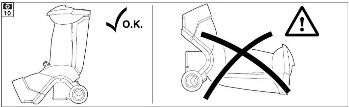
Starting:
Place the machine in a stable and upright position prior to starting. The machine must never be operated in a horizontal position.
Exercise care when switching on the machine and observe the instructions in the section "Operating the machine". ( 10.5)
Do not stand in front of the discharge opening when starting the engine or switching on the motor. There must be no shredding material in the garden shredder when it is started or switched on.
Shredding material may be ejected and lead to injuries.
The machine must not be tilted during start-up.
Avoid switching the machine on repeatedly within a short period of time; particularly avoid "playing" with the On / Off switch. Risk of motor overheating.
Owing to the voltage fluctuations caused by this machine during the start-up, other devices connected to the same circuit may be subject to interference in the case of unfavourable power supply conditions. In this case, appropriate steps should be taken (e.g. connection to a different circuit than the one used by the affected device, or operation of the machine using a circuit with a lower impedance).
Working:

Risk of injury!
Never place your hands or feet above, underneath or on rotating parts.
When the machine is running, never put your face or any other part of your body above the feed chute or in front of the ejection opening. Always keep your head and body away from the feed openings.

Never put your hands or any other part of your body or clothing into the feed chute or ejection chute. There is a
considerable risk of injury to eyes, face, fingers, hands etc.
Always maintain your balance and firm footing. Do not stretch forward.
The splash guard must not be tampered with (removed, folded up, jammed into position, damaged etc.) during operation.
The operator must stand in the working area described when feeding the shredder. Stay inside the working area and outside of the ejection zone at all times during operation of the machine. ( 8.4)
Risk of injury:
Shredding material may be ejected back up during operation. Always wear safety glasses and keep your face away from the feed openings.
Never tilt the machine when the engine or motor is running.
If the machine falls over during operation, immediately switch off the motor and disconnect the mains plug.
Make sure that there is no shredding material blocking the ejection chute, as this could result in a poor shredding performance or kickbacks.
When feeding the garden shredder, pay particular attention to ensuring that no foreign objects such as bits of metal, stones, plastic, glass, etc. get into the shredding chamber as this could result in damage or kickbacks from the feed chute. Remove blockages for the same reason.
Kickbacks can occur when feeding the garden shredder with branch material. Wear gloves.

Beware of the cutting tool running on for several seconds before coming to a standstill.
STOP
Switch off the motor, disconnect the mains plug and allow all
rotating tools to reach a complete standstill
– before leaving the machine unattended
– before repositioning, lifting, carrying, tilting, pushing or pulling the machine
– before unscrewing the closure screw and opening the machine
– before transporting the machine
– before removing blockages at the cutting unit, in the feed chute, in the branch guide or in the discharge chute
– before carrying out any work on the blade discs
– before checking or cleaning the machine or before carrying out any other work on it.
If foreign objects get into the cutting tool or if the machine makes unusual noises or vibrates in an unusual way, switch off the motor immediately and allow the machine to come to rest. Detach the mains plug, remove the feed chute and perform the following steps:
- Check the machine, in particular the cutting unit (blade, blade discs, blade shaft, blade fastening screw, clamping ring) for damage and have any necessary repairs carried out by a technician before starting again and working with the machine.
- Check that all parts of the cutting unit are seated securely, retighten the screws if necessary (observe tightening torques).
- Have damaged parts replaced or repaired by a technician; the parts must be of similar quality.
4.7 Maintenance and repairs

Before carrying out any maintenance operations (cleaning, repair etc.) and before checking whether the
electric cable is entwined or damaged, park the machine on firm, level ground, switch off the motor and disconnect the mains plug.
Allow the machine to cool down for approx. 5 minutes before performing any maintenance operations.
Before performing maintenance of the cutting tool, ensure that the cutting tool can still be turned despite the locking device, even when the power supply is switched off.
The power cable must only be repaired or replaced by authorised electricians.
Cleaning:
The complete machine must be cleaned thoroughly following use. (Ö 11.1)
Never use high-pressure cleaners and do not clean the machine under running water (e.g. using a garden hose). Do not use aggressive cleaning agents. These can damage plastics and metals, impairing the safe operation of your STIHL machine.
Maintenance operations:
Only maintenance operations described in this instruction manual may be carried out. Have all other work performed by a specialist dealer.
If you do not have the necessary expertise or auxiliary equipment, please always contact a specialist dealer.
STIHL recommends that you have maintenance operations and repairs performed exclusively by a STIHL specialist dealer.
STIHL specialist dealers regularly attend training courses and are provided with technical information.
Only use tools, accessories or attachments approved for this machine by STIHL or technically identical parts. Otherwise, there may be a risk of accidents resulting in personal injury or damage to the machine. If you have any questions, please consult a specialist dealer.
The characteristics of original STIHL tools, accessories and spare parts are optimally adapted to the machine and the user's requirements. Genuine STIHL spare parts can be recognised by the STIHL spare parts number, by the STIHL lettering and, if present, by the STIHL spare parts symbol. On smaller parts, only the symbol may be present.
Always keep warning and information stickers clean and readable. Damaged or missing stickers must be replaced by new, original plates from your STIHL specialist dealer. If a component is replaced with a new component, ensure that the new component is provided with the same stickers.
Only perform work on the cutting unit when wearing thick work gloves and exercising extreme care.
Ensure that all nuts, pins and screws, especially all the cutting unit screws, are securely tightened, so that the machine is in a safe operating condition.
Check the entire machine for wear or damage on a regular basis, particularly before extended periods when the machine is not in use (e.g. over winter). For safety reasons, worn or damaged parts must be replaced immediately to ensure that the machine is always in a safe operating condition.
Components or guards that are removed for maintenance operations must be properly reinstalled immediately.
4.8 Storage for prolonged periods without operation
Allow the machine to cool for approx. 5 minutes before storing it in an enclosed space.
Ensure that the machine is protected from unauthorised use (e.g. by children).
Thoroughly clean the machine before storage (e.g. winter break).
Store the machine in good operational condition.
Store the machine on a level surface so that it cannot unintentionally roll away.
Only store the garden shredder with either the feed chute or the blade cover fitted. Risk of injury due to exposed blades.
4.9 Disposal
Waste products can be harmful to people, animals and the environment. They must consequently be disposed of properly.
Consult your recycling centre or your specialist dealer for information on the proper disposal of waste products. STIHL recommends STIHL specialist dealers.
Ensure that old machines are properly disposed of. Render the machine unusable prior to disposal. In order to prevent accidents, always remove the power cable and electric cable to the motor.
5. Description of symbols
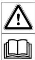
Caution!
Read the instruction manual before initial use.
Risk of injury!
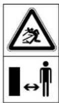
Keep other persons out of the danger area.
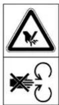
Risk of injury:
Risk of injury caused by rotating tools.
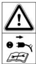
Risk of injury!
Switch off the motor and disconnect the power cable from the machine before working on the cutting tool, before performing maintenance and cleaning work, before checking whether the electric cable is entwined or damaged and before leaving the machine unattended.
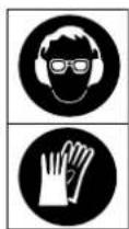
Wear hearing protection.
Wear safety glasses.
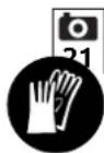
Wear work gloves.

Risk of injury:
Do not climb onto the machine.

Risk of injury:
Never put your hands or any other part of your body or clothing into the feed chute or ejection chute.
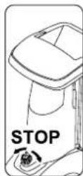
The On / Off switch is located on the front of the machine. Turn the black rotary knob of the On / Off switch to switch off the machine.
6. Standard equipment

Item Designation Qty.
A Basic unit 1
B Feed chute ATO 400 1
C Right wheel carrier 1
D Left wheel carrier 1
E Ejection chute extension 1
F Guiding plate 1
G Ejection chute plate 1
H Axle 1
I Wheel 2
J Wheel cap 2
K Plug 2
L Foot 2
M Torx screw 2 M8x40
N Retaining ring 2
- Torx screw 6 P5x20
Item Designation Qty.
| P Flat head bolt | 1 |
| M6x16 |
| Q Torx screwM6x16 | 2 |
R M6 nut 3
S Installation tool 1
T Hexagon bolt 1 M14x130
• Instruction manual 1
7. Preparing the machine for operation

Risk of injury:
Carefully read the section entitled "For your safety" ( 4.) and follow all the safety instructions before assembling the garden shredder.
Strictly observe all tightening torques in the section "Preparing the machine for operation" ( 7.) to avoid damaging the machine.

Be sure to always wear gloves. The blade cover must be installed. ( 7.5)

Avoid damage to the machine.
When moving the basic unit into the installation position shown, ensure that the electric cable is not damaged (pinched).
Place cardboard underneath the machine to protect it from being scratched.
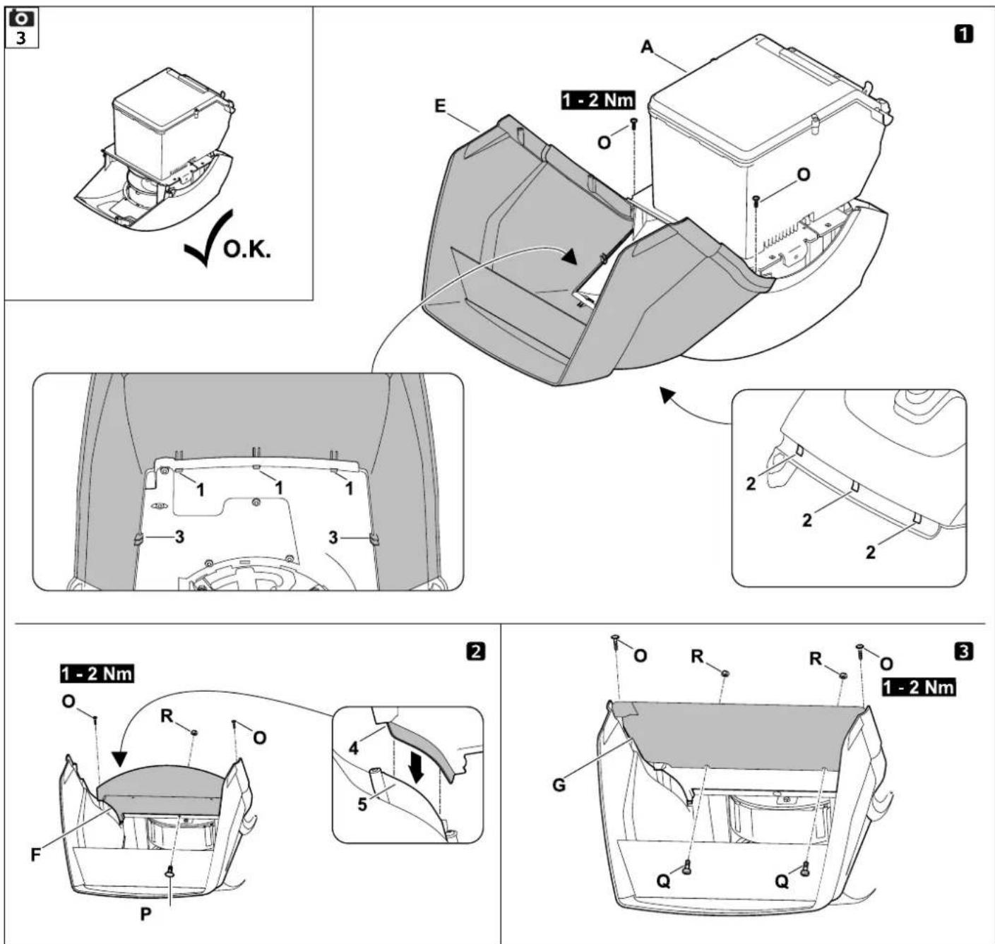
7.1 Installing the ejection chute
- Move the basic unit (A) into the installation position shown.

1 Install the ejection chute extension
- Attach the ejection chute extension (E), engage the hooks (1) in the apertures on the housing (2), turn downwards and push on the retainers (3) at the side.
- Screw in the screws (O) and tighten to 1 - 2 N m.
2 Install the guiding plate
- Insert the guiding plate (F). Ensure that the guides on the guiding plate (4) are correctly located in the guides of the ejection chute extension (5).
• Fit screw (P) and tighten with nut (R). - Screw in the screws (O) and tighten to 1 - 2 N m.
3 Install the ejection chute plate
- Insert the ejection chute plate (G).
- Screw in the screws (O) and tighten to 1 -2 N m.
- Fit screws (Q) and tighten with nuts (R). Any slight tensions occurring in the ejection chute can be compensated by readjusting the screws.
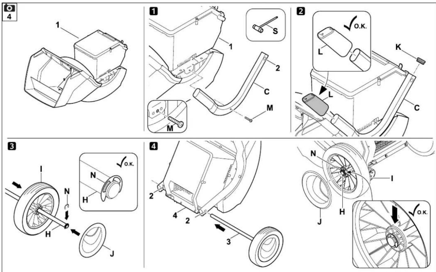
7.2 Attaching the chassis
- Move the basic unit (1) into the installation position shown.

Only install the wheel carriers as described, with the bent section facing outwards. The axle bore (2) must point to the rear.
1 Install right and left wheel carrier:
- Position the right wheel carrier (C) on the basic unit (1) as shown.
- Insert the screw (M) through the bore in the wheel carrier and screw into the centre bore using installation tool (S), but do not tighten.
- Repeat this procedure on the left side.
2 Install the foot and plug:
- Push the foot (L) as far as possible onto the wheel carrier (C) as shown. The foot (L) engages in the wheel carrier (C).
- Carefully drive the plug (K) as far as possible into the wheel carrier (C).
- Repeat this procedure on the left side.
3Mount the wheel on the axle:
- Push the retaining ring (N) as far as possible into the groove in the axle (H).
- Push the wheel (I) onto the axle (H).
• Fit the wheel cap (J).

When installing, ensure that the retaining ring (N) engages in the groove in the axle (H) in order to prevent the wheel from becoming loose.
4 Installing the axle and wheel:
- Push the axle with pre-installed wheel (3) through the bore (2) in the wheel carrier, through the motor cover (4) and through the bore (2) in the second wheel carrier.
- Push the wheel (I) onto the axle (H).
- Push the retaining ring (N) as far as possible into the groove in the axle (H).
• Fit the wheel cap (J).
- Raise the basic unit into the working position.
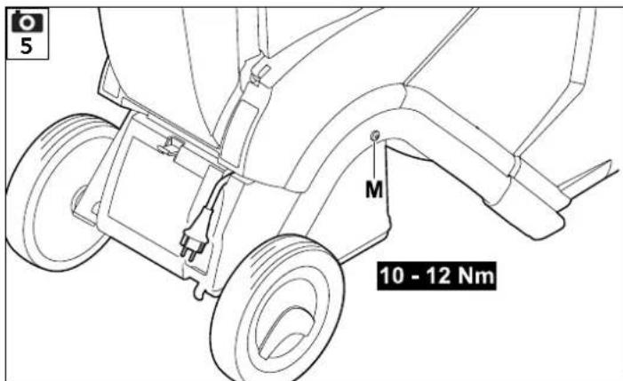
7.3 Tightening the screws of the wheel carrier mounting:

- Place the machine on firm and level ground.
- Tighten the screws (M) of the wheel carrier mounting to 10 - 12 Nm.
After tightening the screws (M), check that both wheel carriers are securely seated.
7.4 Removing the blade cover

- Hold the blade cover (1) at the bore and lift off the cover.
7.5 Installing the blade cover

- Insert the blade cover (1) under the counter-blade (2). Then press down the blade cover (1). When properly installed, the blade cover (1) must lie against the blade disc correctly.
7.6 Installing the feed chute ATO 400

- Remove the blade cover. (⇒ 7.4)
- Insert the two fastening hooks (1) on the feed chute ATO 400 (B) into the two openings (2) in the basic unit (A).
- Tilt the feed chute ATO 400 (B) forwards to the stop.
- Screw in the On / Off switch (3) and tighten.
Following assembly, check that the feed chute ATO 400 is correctly engaged in both openings in the basic unit.
8. Notes on working with the machine
8.1 What material can be processed?
Both soft and hard material can be processed with the garden shredder.
Soft material:
Organic plant trimmings such as fruit and vegetable waste, flower cuttings, leaves etc.
- Shredding soft material. ( 8.9)
Hard material:
Tree and hedge cuttings and thick branch material with side shoots.
- Shredding hard material. ( 8.9)
Tree and hedge cuttings should be processed when fresh, as the shredding performance is better with fresh than with dried-out or wet material.
8.2 What material cannot be processed?
Stones, glass, bits of metal (wire, nails, etc.) or plastic must not be fed into the garden shredder.
As a general rule:
Any materials that do not belong on the compost heap should not be processed using the garden shredder.
8.3 Maximum branch diameter
The data relates to freshly cut branch material:
Maximum branch diameter
GHE 420: 50 mm GHE 450: 55 mm

The size of the feed opening of the branch guide serves only to better accommodate branch material with side shoots and does not indicate the maximum permitted diameter of the shredding material.
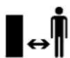
8.4 Working area for operator

- For safety reasons, the operator must stay within the working area (grey area X) for the entire operating period.

Risk of injury:
To ensure you are not hit by shredding material that is ejected backwards when processing hard material (branch guide (1) folded out), you should stand slightly to one side of the garden shredder (see grey area X) and not directly behind it.
8.5 Working position of the machine

The garden shredder must only be operated in an upright position. The garden shredder must be stood on its two wheels and on the two wheel carriers as shown for the entire period of operation.
8.6 Correct machine load
The load on the motor or engine of the garden shredder must never cause the speed to drop significantly. Always feed the garden shredder continuously and steadily. If the speed drops when working with the garden shredder, stop feeding the machine in order to relieve the load on the motor or engine.
8.7 Overload protection
If an overload of the motor occurs during operation, the built-in overload protection device automatically switches off the motor.
The garden shredder can be started up again after a cooling period of approx. 10 minutes. Frequent triggering of the overload protection may be attributable to the following causes:
- Unsuitable electric cable (⇒ 10.1)
- Power overload
- Machine overloaded due to excessive quantities of shredding material or blunt blades
8.8 If the cutting unit of the garden shredder becomes blocked
If the cutting unit of the garden shredder becomes blocked during shredding, immediately switch off the motor and disconnect the power cable. Then remove the feed chute ATO 400 and eliminate the cause of the malfunction.
8.9 Feeding the garden shredder


Risk of injury!
Carefully read the section entitled "For your safety" (⇔ 4.), subsection "Working with your machine" (⇔ 4.6) in particular, and follow all the safety instructions before feeding the garden shredder. It is only permitted for one person to feed the garden shredder.

Risk of injury!
Never reach into the feed opening.

Observe the correct motor load. (⇒ 8.6)
Do not feed material into the two feed openings (1, 2) on the garden shredder at the same time. Danger of blocking.
Soft material:
- Before feeding the garden shredder, note the working area. ( 8.4)
- Start the garden shredder. (⇒ 10.5)
- Throw organic plant trimmings such as fruit and vegetable waste, flower cuttings, leaves, thin branches etc. into the feed opening (1) for soft material.


The feed opening (1) is only for feeding with soft material or with thin branches (up to approx. 10 mm in diameter) with numerous side shoots and twigs. The branch guide (3) should be folded in when feeding soft material into the shredder. ( 10.10)
Damp or wet soft material will cause blockages in the machine more quickly. For this reason, feed the garden shredder more slowly and pay particular attention to the motor speed. It should not drop during feeding.
Hard material:
- Before feeding the garden shredder, note the working area. (⇒ 8.4)
- Fold out the branch guide (3). (⇒ 10.9)
- Observe the maximum branch diameter. ( 8.3)
- Start the garden shredder. (⇒ 10.5)

Risk of injury:
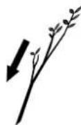
In order to prevent injuries caused by kickback, the garden shredder must be fed with hard material in the correct manner. If the garden shredder is fed from the rear (i.e. the operator is standing in the working area ( 8.4), the branch material should be inserted at a slight angle and guided along the left-hand chute wall to the blade unit in accordance with the symbol (4). When feeding, note the maximum branch diameter. ( 8.3) The large feed opening (2) is designed to better accommodate branches with numerous side shoots and twigs.

Cut up thick branches and branches with numerous side shoots (note the maximum branch thickness) beforehand using loppers. Throw thin pruning material (up to approx. 10 mm in diameter) into the feed opening (1) for soft material.
- Feed tree and hedge cuttings and branch material slowly into the feed opening (2) of the folded-out branch guide (3). The hard material is automatically drawn in by the machine. You should support and guide longer branches with your hand when shredding.
9. Safety devices
9.1 Motor restart inhibitor
The machine can only be started via the switch and not by plugging the electric cable into the mains socket.
9.2 Safety interlock
The garden shredder may only be operated when the feed chute ATO 400 is properly closed. If the On-/Off switch is released during operation, the motor or the engine is switched off automatically and the shredding tool comes to a standstill within a few seconds. In addition, the two blade discs are mechanically locked automatically if the feed chute ATO 400 is removed.
9.3 Motor run-down brake
The motor run-down brake shortens the run-down time from when the machine is switched off until the blades stop to a few seconds.
10. Operating the machine

Risk of injury:
Carefully read the section entitled "For your safety" ( 4.) and follow all the safety instructions before operating the garden shredder.
10.1 Electrical connection of garden shredders

Risk of injury!
Observe the instructions in section "Warning – dangers caused by electrical current" ( 4.2).

The UK version of the garden shredder has a 10 m electric cable with a special plug. A plug-in fuse is included in this UK plug.
Power supply and operating voltage must correspond (see rating plate).
The power cable must be adequately protected by fuse. ( )
Only electric cables which are no lighter than rubber sheathed cables
H07 RN-F DIN/VDE 0282 may be used.
The plug connections must be splash proof. Unsuitable extension cables lead to a loss of power and may result in damage to the motor.
GHE 420:
The minimum cross-section of the power cable must be 3 × 1.5 mm^2 for a length of up to 25 m or 3 × 2.5 mm^2 for a length of up to 50 m.
The connectors of the electric cable must be made of rubber or have a rubber coating and conform to the DIN/VDE 0620 standard.
This machine is intended for operation with a power supply having a system impedance of Z_max at the transfer point (house connection) of maximum 0.334 ohms (at 50Hz).
The user must ensure that the machine is only operated with a power supply which
meets this requirement. If necessary, this information can be obtained from the local electric power company.
GHE 450:
The minimum cross-section of the power cable must be 5 × 1.5 mm^2 for a length of up to 25 m or 5 × 2.5 mm^2 for a length of up to 50 m. The plug connections of the electric cables must be CEE-plug devices and conform to the DIN/VDE 0623 standard.

Your electrician can provide further information on mains connection.
10.2 Connecting the power cable

When choosing a power cable, take account of all the information in the "Electrical connection" section ( 10.1).
GHE 420:
- Connect the power cable connector to the 3-pin mains plug on the machine.
- Attach the cable to the strain relief. (⇔ 10.4)
GHE 450:
- Connect the power cable connector to the 5-pin mains plug on the machine.
- Attach the cable to the strain relief. (⇒ 10.4)
10.3 Disconnecting the power cable
- Detach the strain relief. (⇒ 10.4)
In order to prevent damage to the power cable, it must only be disconnected by pulling at the connector. Never pull at the cable.
10.4 Strain relief
During work, the strain relief prevents any unintentional disconnection of the electric cable and any resulting damage to the mains connection on the machine. For this reason, the electric cable must be fed through the strain relief.
Attaching the cable to the strain relief:
- Connect the power cable. (⇒ 10.2)
- Form a loop in the power cable (1) and guide it through the opening (2).
- Then push the loop over the hook (3) and pull it tight.
Detaching the cable from the strain relief:
- Remove the loop of the power cable from the hook (3).
- Pull the loop of the power cable (1) out of the opening (2).
- Disconnect the power cable if necessary. (⇒ 10.3)
10.5 Switching on the garden shredder


Risk of injury:
Carefully read the section entitled "For your safety" ( 4.) and follow all the safety instructions before operating the garden shredder.
Before use, check that the feed chute ATO 400 is properly closed and the On / Off switch (1) has been tightened hand-tight.
- Connect the power cable. (⇒ 10.2)
- Press in the green button (2) (symbol I) as far as it will go. The green button locks into place and remains pressed down. The garden shredder starts up.
10.6 Switching off the garden shredder


Risk of injury!
Do not step into the ejection area when switching off!
Stand to the side of the machine to do so.
Beware of the work tools running on for several seconds before coming to a standstill after switching off the motor.

Note the pictogram on the front of the upper chute.
Only switch off the motor when there is no further shredding material in the machine, otherwise this could cause a blockage at one of the two blade discs when t is used next.
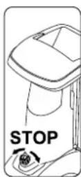
- The garden shredder is switched off by turning (in either direction) the black knob (1) (symbol 0) at the On-/Off switch. The garden shredder motor is switched off and braked automatically.
10.7 Checking rotational direction of blade discs GHE 450.

With the GHE 450 model, the rotational direction of the blades must be checked before commencing work (feeding).

Risk of injury! Always wear safety glasses when performing the check. Press the splash guard inwards until the blade disc becomes visible. Never place your hands near the blade disc.
- Connect the power cable. (⇒ 10.2)
- Fold out the branch guide. (⇒ 10.9)
- Switch on the garden shredder. (⇒ 10.5)
- Switch off the garden shredder. (⇒ 10.6)
- Press the branch guide splash guard inwards and look from above into the feed opening of the branch guide: The correct rotational direction of the blade disc is clockwise.
10.8 Change rotational direction of blade disc GHE 450


In the case of incorrect rotational direction (anti-clockwise) of the blade disc, the rotational direction must be changed on the GHE 450 model.
The rotational direction of the blade discs can be changed by reversing the polarity of the phase rotation device on the mains plug.
- Turn the phase rotation device (1) 180° clockwise or anti-clockwise until it engages using a screwdriver (2).
10.9 Folding out the branch guide


Risk of injury:
For safety reasons, only fold the branch guide (2) in and out when the machine is switched off.
- Press branch guide lock (1) upwards and hold.
- With your other hand, move the branch guide (2) slowly to the rear (away from the machine).
- Release the branch guide lock (1) again and fold out the branch guide (2) as far as possible.
10.10 Folding in the branch guide


Risk of injury:
For safety reasons, only fold the branch guide (1) in and out when the machine is switched off.
Danger of pinching:
When closing the branch guide, make sure that your fingers are not pinched between the branch guide and the feed chute.
- Slowly fold in the branch guide (1) as far as possible (press against the machine) until it latches into the branch guide lock (2).
10.11 Tool box

To open the tool box:
- Press the tab (1) downwards and hold.
- Fold down the tool box lid (2).
Closing the tool box:
- Push the tool box lid (2) until the tab latches into place.
10.12 Shredding
- Push the garden shredder onto firm and level ground and set down safely.
- Put on thick gloves, safety glasses and hearing protection.
- Connect the power cable to the garden shredder. (⇒ 10.2)
- GHE 450: Check the rotational direction of the blade disc and change if necessary. ( 10.7)
- For hard material (e.g. tree- and hedge cuttings) fold out the branch guide. (⇒ 10.9)
- Start the garden shredder. (⇒ 10.5)
- Wait until the garden shredder has reached its maximum speed (idling speed).
- Feed the garden shredder with shredding material in the correct way. ( 8.9)
- Switch off the garden shredder. (⇒ 10.6)
11. Maintenance

Risk of injury:
Carefully read the section "For your safety" ( 4.), particularly the subsection "Maintenance and repairs" ( 4.7), and follow all safety instructions exactly before performing any maintenance or cleaning operations on the machine.
Disconnect the mains plug before performing any maintenance operations.
11.1 Cleaning the machine


Risk of injury:
If the blade discs are covered with shredding material, use a brush or similar to remove this shredding material.
Do not wipe the housing with your hand. Risk of injury from the blades.
Maintenance interval:
After each use
Clean the machine thoroughly each time it has been used. Care of the machine will protect it against damage and extend its service life.
It is only permitted to clean the machine in the position shown.
- Remove the feed chute. (⇒ 11.2)
Remove dirt from the cooling air guide (inlet slots) on the motor housing to ensure that the motor is adequately cooled.

Never spray water onto motor or engine components, seals, bearing points or electrical parts such as switches. This would result in
expensive repairs.

If you are unable to remove the dirt and accumulated deposits with a brush, a damp cloth or a stick, STIHL recommends the use of a
special cleaner (e.g. STIHL special cleaner).
Do not use aggressive cleaning agents.
Clean the blade discs regularly.
11.2 Removing the feed chute ATO 400


Risk of injury:
Switch off the machine. Disconnect the mains plug before unscrewing the On / Off switch (1).
Always wear thick gloves.
If it is not possible to perform any work on the blade discs after removing the feed chute, always fit the blade cover for safety reasons. ( 7.5)
- Disconnect the power cable. (⇒ 10.3)
- Unscrew the On / Off switch (1) and remove.
- Fold the feed chute ATO 400 (2) backwards and remove.

The locking device for the blade discs is activated automatically after the chute has been removed.
When locked, the blade disc is still able to turn approx. 360^ as far as the stop.
11.3 Removing the blade discs

Risk of injury:
Always wear gloves.
Do not touch the blades until they have come to a standstill.
- Remove the feed chute ATO 400. (⇒ 11.2)
1 Unscrew the blade fastening screw:
- Position the assembly tool (1) on the blade fastening screw (2) and turn anticlockwise slowly and carefully until the blade discs are stopped by the stop. Detach the assembly tool (1).

In order to prevent injuries, the blade cover must always be attached when loosening the blade fastening screw (see view ☐).
• Install the blade cover. ( 7.5)
- Insert the assembly tool (1) into the bore of the blade cover (3) and position on the blade fastening screw (2).
- Loosen the blade fastening screw (2) using the assembly tool (1) and unscrew completely.
- Remove the blade cover. (⇔ 7.4)
- Remove the blade fastening screw (2), lock washer (4) and clamping ring (5).
2To remove the wing blade and blade disc for soft material:
- Remove the short wing blade (6) and long wing blade (7).
- Lift off the soft material blade disc (8).
3 Remove the insert: - Unscrew and remove the screws (9). Lift off the insert (10).
4 To remove the blade holder and blade disc for hard material: - Tighten the screw (11) using the assembly tool (1) and in doing so detach the blade holder (12).
• Unscrew and remove the screw (11). - Remove the blade holder (12) together with the clamping ring (13).
- Lift off the hard material blade disc (14).
11.4 Installing the blade discs

Risk of injury! Always wear gloves.
Observe the specified tightening torque of
36 - 44 Nm when tightening the blade fastening screw, as the secure attachment of the two blade discs depends on this. Before attaching the two blade discs, check to see that they are OK and not bent and the blades have no notches, cracks or pieces chipped out.
Observe the wear limits of the blades. ( 11.9)
Both blade discs must always be installed.
Carry out each assembly step from 1 to 5.

Clean the two blade discs and the blade disc mounting on the machine before installing. Furthermore, ensure that the feather key is inserted in the blade shaft.
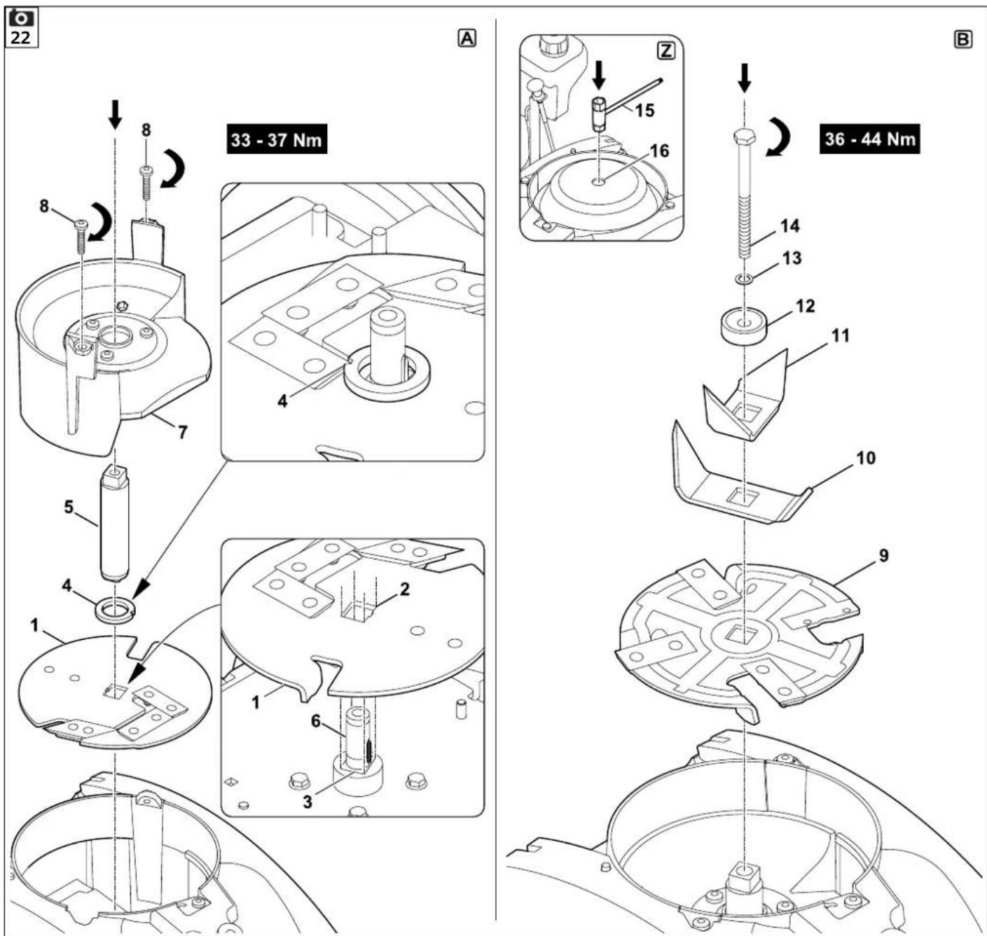
1. Insert the hard material blade disc (Figure A)
- Insert the hard material blade disc (1) with the three fitted blades facing upwards.
Allow the rectangular blade mounting (2) of the blade disc to engage in the rectangular mounting (3) in the bearing ring.


- Install the blade holder with the clamping ring (Figure A):

Position the notch in the clamping ring at the corner of the blade so that the clamping ring lies flat on the blade disc.
- Place the clamping ring (4) onto the blade disc (notch in the clamping ring must enclose the blade).
-
Push the blade holder (5) onto the drive shaft (6). Make sure that the blade holder engages in the blade disc (1) and drops down in the clamping ring (4) as far as possible.
-
Install the insert (Figure A):

The insert can only be installed as shown. It cannot be inserted in any other position.
• Install the insert (7) as shown.
- Screw in the screws (8) and tighten to 33 - 37 Nm.
- Insert the soft material blade disc and wing blade (Figure B):
- Insert the soft material blade disc (9) with the four fitted blades facing upwards.

Always insert the longer wing blade of the two first. Then insert the second wing blade at 90^ to the first wing blade.
- Insert the long wing blade (10). Insert the short wing blade (11) at 90° to the long wing blade.
- Fasten the blade discs (Figure B):
- Attach the clamping ring (12) and tighten together with the lock washer (13) and the blade fastening screw (14).
- Position the assembly tool (15) on the blade fastening screw (14) and turn clockwise slowly and carefully until the blade discs are stopped by the stop. Detach the assembly tool (15).

Risk of injury:
The blade cover must always be attached in order to tighten the blade fastening screw (see view Z).
• Install the blade cover. ( 7.5)
- Insert the assembly tool (15) into the bore of the blade cover (16) and position on the blade fastening screw (14).
- Tighten the blade fastening screw (14) to 36 - 44 Nm.
• Install the feed chute ATO 400. (⇒ 7.6)
11.5 Removing the counter-blade


Risk of injury:
Always wear thick gloves.

- Remove the feed chute ATO 400 and the blade cover. (⇒ 11.2), (⇒ 7.4)
• Unscrew and remove the screw (1). - Remove the counter-blade (2) from above.
11.6 Installing the counter-blade


Risk of injury:
Always wear thick gloves.

- Remove the feed chute ATO 400 and the blade cover. (⇒ 11.2), (⇒ 7.4)
- Insert the counter-blade (1) into the mounting (2) in the housing.
- Screw in the screw (3) and tighten to 28 - 32 Nm.
• Install the feed chute ATO 400. (⇒ 7.6)
11.7 Reversing the blades


Risk of injury:
Always wear thick gloves.


When the blades are blunt, we recommend that you reverse all the blades on the particular blade disc. All blades (regardless of the blade geometry) are reversed in the same way.
- Removing the blade discs. (⇒ 11.3)

Risk of injury:
To prevent injuries, always clamp down the blade discs before installing or removing the blades.
Reversing the four blades of the soft material blade disc (Figure A):
1. Removing:
- Unscrew screws (1) and remove together with nuts (2).
- Remove blade (3) upwards.
2. To install:
- Clean the blade disc.
- Reverse blade (3) and place onto the blade disc with the sharp edge exposed and align the bores.
- Insert screws (1) through the bores and screw on nuts (2). Tighten nuts (2) to 8 --10 Nm.
Reversing the three blades of the hard material blade disc (Figure B):
1. Removing:
- Unscrew the screws (4) and M8 screws (5) and remove them together with the nuts (6) and M8 nuts (7).
- Lift off the blades (8) and blade (9).
2. To install:

There must be no gap between the two blades (8) following installation. A gap between the two blades impairs the feeding function.
- Clean the blade disc.
- Reverse the blades (8) and place onto the blade disc with the sharp edge exposed and align the bores.
- Insert screws (4) through the bores and screw on nuts (6). Do not tighten.
- Press the two blades (8) together (see small illustration) and hold. There must be no gap between the two blades (8).
• Tighten nuts (6) to 8 - -10 Nm. - Reverse the blade (9) and place onto the blade disc with the sharp edge exposed.
- Insert the M8 screws (5) through the bores, screw on the M8 nuts (7) and tighten to 16 - 20 Nm.
11.8 Sharpening the blades

We recommend that all blades are sharpened only by a specialist dealer, as the function (drawing in of shredding material, durability of the cutting edges etc.) of the garden shredder may deteriorate if blades are ground incorrectly (wrong sharpening angle, imbalanced due to unevenly ground blades etc.).
Always wear safety glasses when sharpening. Make sure that others are kept out of the danger area.
- Removing the blade discs. (⇒ 11.3)
- Remove the blade. (⇒ 11.7)
Sharpening angle:
The sharpening angle for all the blades is 30^ .
Instructions for sharpening the blades:
The following points must be observed when re-sharpening the blades:
- Cool the blades when sharpening, e.g. with water. The blade must not be allowed to display blue colouring, as this would reduce its cutting quality.
- Sharpen the blade evenly to prevent vibrations due to imbalance.
- Check blades for damage before installing: The blades must be replaced if notches or cracks are visible or if the blades have reached the wear limits.
- Re-sharpen the cutting edges to the specified sharpening angle.
- Sharpen the blades against the cutting edge.
- After sharpening, remove any sharpening burr at the cutting edge using fine sandpaper.
11.9 Wear limits of the blades


The blades must be reversed or replaced before reaching the specified wear limits (A, B, C, D). STIHL recommends STIHL specialist dealers.

The specified values should be measured at several points (two or three recommended) along the cutting edge on all the blades.
Use the smallest value for a blade.
We recommend that you always reverse or replace all the blades at the same time.
1 Blade overview
2 wing blades (1)
6 blades (2)
1 blades (3)
1 counter-blade (4)
Soft material blade disc:
The soft material blade disc is fitted with four blades.
Hard material blade disc:
The hard material blade disc is fitted with two blades and one chipping blade.
- Removing the blade discs. (⇔ 11.3)
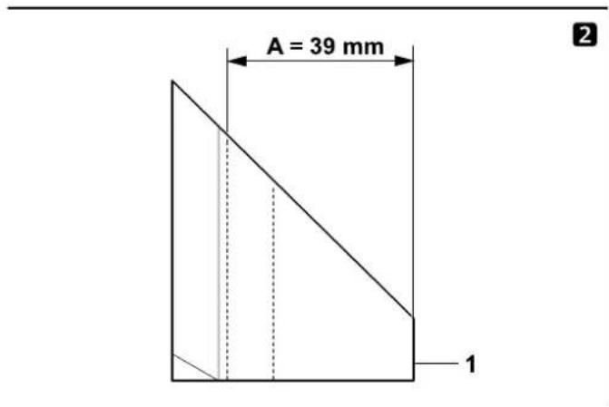
2 wear limit of wing blades (1):

The measurement procedure and the value specified are the same for both wing blades.

Asymmetrical wear may occur at the two wing blades due to uneven use of the cutting edges.
Minimum blade width (A) of the two wing blades (1):
A = 39 mm
3 Wear limit of blades (2):

The blades (2) are reversible blades. After reaching the specified wear limit (B), the blade can be re-sharpened and reversed until the wear limit is reached, before needing to be replaced.
- Measure the distance (B) shown in the illustration from the large diameter of the bore to the cutting edge (X).
- Repeat this procedure at the second bore on the blade.
Minimum distance (B) on the blades (2):
B = 6 mm

The particular blade (2) must be reversed or replaced if one of the two distances measured is less than the minimum distance (B).
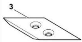
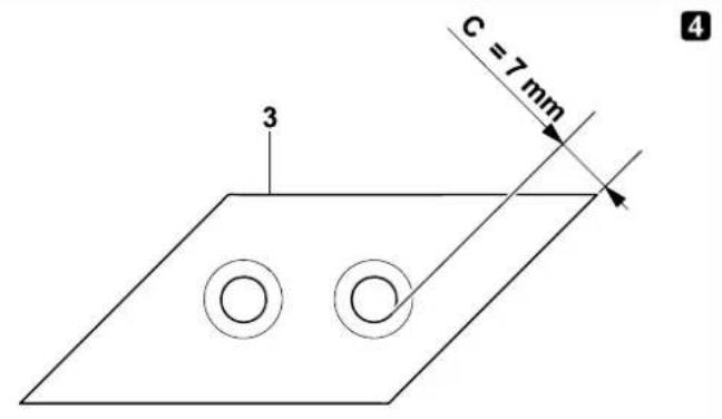
4 Wear limit of blade (3):

The blade (3) is a reversible blade. On reaching the specified wear limit (C), the blade (3) can be re-sharpened and reversed until the wear limit is reached, before needing to be replaced.
- Measure the distance (C) at a right angle to the cutting edge.
Minimum distance (C) on the blade (3):
C = 7 mm
The blade (3) must be reversed or replaced if the distance measured is less than the minimum distance (C).
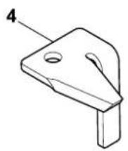
5Wear limit of counter-blade (4):
Asymmetrical wear may occur at the counter-blade (4) due to uneven use of the cutting edge.
- The counter-blade (4) must be replaced before the edge (D) at the tip (5) of the blade is ground down and no longer visible.
11.10 Electric motor and wheels
The electric motor is maintenance-free.
The wheel bearings are maintenance-free.
11.11 Service intervals
Service by the specialist dealer
We recommend that you have your garden shredder serviced once a year by a specialist dealer.
STIHL recommends STIHL specialist dealers.
Professional use (commercial use of the garden shredder):
every six months
Private use:
once a year
Service intervals for cutting unit:
Before each use:
Check that the cutting unit (consisting of blade disc, blades, retaining washer, clamping ring and screw) is seated securely and that there are no cracks or other damage.
Check the wear limits of the blades.
(⇒ 11.9)
11.12 Storage and winter break
Store the garden shredder in a dry and locked place that is generally free of dust. Make sure that the machine is kept out of the reach of children.
Only store the garden shredder in good operating condition and with the feed chute ATO 400 or blade cover fitted.
Keep all nuts, pins and bolts tightly fastened, replace danger signs and warnings on the appliance that have become illegible, check the entire machine for wear and damage. Replace all worn or damaged parts.
Any machine faults must be completely remedied prior to storage.
Note the following points when storing the garden shredder for extended periods (over winter):
- Thoroughly clean all external parts of the machine
- Thoroughly lubricate/grease all moving parts.
12. Transport


Risk of injury:
Carefully read and observe the section entitled "For your safety", in particular the "Transport" section. ( 4.4)
Only transport the garden shredder with the feed chute ATO 400 fitted and the branch guide folded in.
If the garden shredder is transported without the feed chute ATO 400, the blade cover must be fitted for safety reasons (exposed blades). ( 7.5)
The garden shredder must be carried by two persons wearing suitable safety clothing (safety shoes, gloves).
Before lifting or tilting the machine, note the weight indicated in the "Technical specifications" section. ( 17.)
Pulling or pushing the garden shredder (Figure A):
- Hold the garden shredder at the transport handle (1) and tilt to the rear until the machine is standing on its wheels.
- The garden shredder can be pulled or pushed slowly (walking pace).

Risk of injury at steps, stepped areas and sloping ramps.
Because of the weight, particular care is required at steps, kerbs, stepped areas, other raised areas and sloping ramps.
Push and do not pull the machine down steps, stepped areas and other raised areas and sloping ramps. The user must always stand higher than the machine, in order to avoid being run over by the machine in the case of loss of control.
Do not push the machine down more than two or three steps. Where there are more steps, carry the machine with the help of a second person.
Risk of injury due to the heavy weight of the machine.
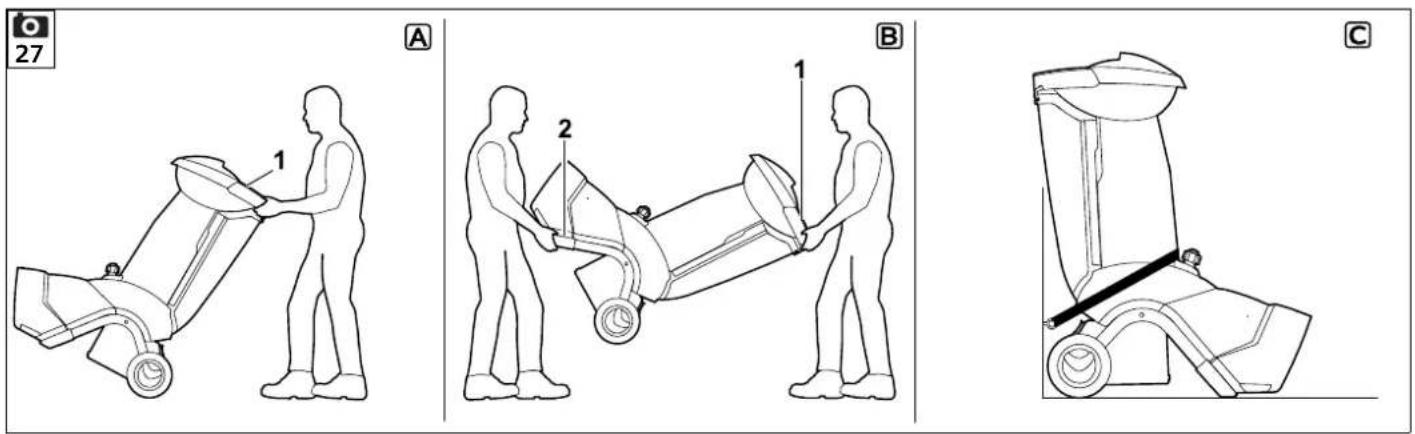
Lifting or carrying the garden shredder (Figure B):

Due to its heavy weight (> 50 kg), we strongly recommend that you do not carry the machine, but only move it on its wheels by pushing.
Suitable lifters must be used when lifting or carrying the machine for short distances.
Two persons are always required to manually lift the machine. Wear suitable protective

clothing; the lower arms and upper part of the body must be fully covered.
- Hold the garden shredder at the transport handle (1) and at the two black feet (2) and lift/carry.
Transporting the garden shredder on a load floor (Figure C):

Risk of injury:
Always secure the garden shredder before transporting. Never transport the machine unsecured.
When transporting the garden shredder, secure it on a load floor using suitable fastening material to prevent it from slipping. Attach ropes or straps at the following points on the machine:
- Axle (inside of the wheel carrier)
- Left wheel carrier
- Right wheel carrier
- Feed chute ATO 400
13. Minimising wear and preventing damage
Important information on maintenance and care of the product group
Electric garden shredder (STIHL GHE)
STIHL assumes no liability for material or personal damage caused by the non-observance of information contained in the operating instructions, in particular with regard to safety, operation and maintenance, or which arise through the use of unauthorised attachment or spare parts.
Please always observe the following important information for the prevention of damage or excessive wear to your STIHL machine:
1. Wearing parts
Some parts of the STIHL machine are subject to normal wear even when used properly and must be replaced in due time depending on type and duration of use.
These include:
- Blade
- Blade disc
2. Compliance with the information in this instruction manual
The STIHL machine must be used, maintained and stored with the care described in this instruction manual. Any damage caused by non-compliance with the safety, operating and maintenance instructions is the sole responsibility of the user.
This applies in particular to:
– Inadequately dimensioned power cables (cross section)
- Incorrect electrical connection (voltage)
– Product modifications not approved by STIHL
– Use of tools or accessories which are not approved or suitable for the machine, or are of inferior quality
- Improper use of the product
– Use of the product for sporting or competitive events
- Resultant damage due to continued use of the product with defective components.
3. Maintenance operations
All operations listed in the section "Maintenance" must be performed regularly.
If these maintenance operations cannot be carried out by the user, a specialist dealer must be commissioned to perform them.
STIHL recommends that you have maintenance operations and repairs performed exclusively by a STIHL specialist dealer.
STIHL specialist dealers regularly attend training courses and are provided with technical information.
If these operations are neglected, faults may arise which are the responsibility of the user.
These include:
- Damage to the motor as a result of inadequate cleaning of the cooling air guide (inlet slots, cooling ribs, fan wheel).
– Corrosive and other resultant damage caused by incorrect storage.
– Damage to the machine through the use of inferior-quality spare parts.
– Damage due to untimely or inadequate maintenance or damage due to maintenance or repair work not performed in the workshops of specialist dealers.
14. Standard spare parts
Soft material blade disc assembly: 6012 700 5110
Hard material blade disc assembly: 6012 700 5100
Long wing blade: 6012 702 0310
Short wing blade: 6012 702 0300
Blade (x6): 6008 702 0121
Blade (x1):
6012 702 0100
Counter-blade:
6012 702 0500
15. Environmental protection
Shredding material should be composted and not disposed of in household waste.
The machine, its packaging and accessories are all produced
from recyclable materials and must be disposed of accordingly.
By disposing of materials separately, and in an environmentally friendly manner, valuable resources can be re-used. For this reason, the machine should be disposed of for recycling at the end of its useful life.
15.1 Disposal
Render the machine unusable prior to disposal.
In particular, remove the power cable and electric cable to the motor for this purpose.
Risk of injury from the blades.
Always store an old garden shredder in a safe place prior to scrapping. Make sure that the machine and the blades are kept out of the reach of children.
16. EU - Declaration of conformity
16.1 STIHL GHE 420.0, GHE 450.0 Garden Shredder
declares under our sole responsibility that
– design: electric garden shredder
– manufacturer's brand: STIHL
-type: GHE 420.0, GHE 450.0
- serial number: 6012
complies with the relevant provisions of Directives 2000/14/EC, 2006/42/EC, 2014/30/EU and 2011/65/EU and has been developed and manufactured in accordance with the versions of the following standards valid on the date of manufacture: EN 50434, EN 60335-1, EN 55014-1, EN 55014-2, EN 61000-3-2 and EN 61000-3-3 (where applicable).
Name and address of relevant, named location:
TÜV Rheinland LGA Products GmbH Tillystrasse 2
D-90431 Nuremberg
The measured and guaranteed sound power levels were determined in accordance with Directive 2000/14/EC, Appendix V.
GHE 420.0
– Measured sound power level: 102.1 dB(A)
– Guaranteed sound power level: 106 dB(A)
GHE 450.0
- Measured sound power level: 104.2 dB(A)
– Guaranteed sound power level: 108 dB(A)
The technical documents are stored in the Product Approval department at STIHL Tirol GmbH.
The year of manufacture and machine number are indicated on the garden shredder.
Langkampfen, 02.11.2020
STIHL Tirol GmbH
p.p.

Matthias Fleischer, Head of Research and Development Division
p.p.

Sven Zimmermann, Head of Quality Division
17. Technical specifications
GHE 420.0 / GHE 450.0:
Serial number 6012
Frequency 50 Hz
Protection class I
Type of protection Splash proof (IPX4)
Operating conditions P40
40 s load time 60 s idle time
Cutting unit Multi-Cut 450
Nominal motor speed 2800 rpm
Cutting unit drive Permanent
Wheel diameter 250 mm
L/W/H 108/51/137 cm
Weight 52 kg / 52 kg
GHE 420.0:
| Electric motor (~) | |
| Motor, design | |
| Type | BSRBF 0.75/2-C |
| Voltage | 230 V |
| Power input | 3000 W |
| Fuse | 16 A * |
| In accordance with Directive | |
| 2000/14/EC: | |
| Guaranteed sound power level L_WAd | 106 dB(A) |
| In accordance with Directive | |
| 2006/42/EC: | |
| Sound pressure level at workplace L_pA | 98 dB(A) |
| Uncertainty K_pA | 4 dB(A) |
| Maximum branch diameter | 50 mm |
GHE 450.0:
| Motor, design | Electric motor (3~) |
| Type | BSRF 0.75/2-C |
| Voltage | 400 V |
| Power input | 3800 W |
| Fuse | 10 A |
| In accordance with Directive | |
| 2000/14/EC: | |
| Guaranteed sound power level L_WAd | 108 dB(A) |
| In accordance with Directive | |
| 2006/42/EC: | |
| Sound pressure level at workplace L_pA | 95 dB(A) |
| Uncertainty K_pA | 4 dB(A) |
| Maximum branch diameter | 55 mm |
\* Warning
In the case of mains fuses of less than 16 A, these may be tripped during start-up or in the case of high load operation of the machine.
17.1 REACH
REACH is an EC Directive for the registration, evaluation, authorisation and restriction of chemicals.
Information on compliance with the REACH Directive (EC) No. 1907/2006 is available from www.stihl.com/reach.
18. Troubleshooting
If necessary, contact a specialist dealer; STIHL recommends STIHL specialist dealers.
Fault:
Motor does not start
Possible cause:
– Motor overload protection activated
- No mains voltage
– Electric cable, plug, plug connector or switch defective
- Fuse in UK plug damaged (only applies to machines for UK)
- Feed chute ATO 400 not properly closed - safety cut-off switch actuated (safety interlock)
- Blade disc blocked
Remedy:
- Allow machine to cool down ( 8.7)
- Check power cable and fuse ✗ (⇒ 10.1)
- Check cable, plugs, connector and switch and replace if necessary (by electrician) ✗ (⇒ 10.1)
- Replace fuse ✗ (⇒ 10.1)
- Close feed chute ATO 400 properly and fasten (tighten On-/Off switch) ( 7.6)
- Remove feed chute and remove shredder deposits from the housing (Important: disconnect the power cable) ( 11.2)
Fault:
Reduced shredding performance
Possible cause:
- Blunt blades
- Incorrectly ground blades
-
Power cable too long
-
Bent blade disc
– GHE 450: Incorrect rotational direction of blade disc
Remedy:
- Reverse or sharpen blades ✗ (⇒ 11.7), (⇒ 11.8)
- Sharpen blades correctly ✗ (⇒ 11.8)
- Use shorter power cable (⇒ 10.1)
- Check blade disc visually ✗
– GHE 450: Change rotational direction of blade disc ( 10.7), ( 10.8)
Fault:
Shredding material is not drawn in
Possible cause:
– GHE 450: Incorrect rotational direction of blade disc
- Blunt or incorrectly ground blades
- Gap between the two blades (hard material blade disc)
- Blade cover not removed
Remedy:
– GHE 450: Change rotational direction of blade disc ( 10.7), ( 10.8)
- Regrind blade and ensure sharpening angle is exactly correct ✗ (⇒ 11.8)
- Install blades onto the hard material blade disc without a gap ( 11.7)
- Remove blade cover ( 7.4)
19. Service schedule
19.1 Handover confirmation
Model:
Serial number:
Date:

natural_image
Simple line drawing of a mechanical component with a cylindrical top and rectangular base (no text or symbols)Next service

19.2 Service confirmation
Please hand this instruction manual to your STIHL specialist dealer in the case of maintenance operations. He will confirm the service operations performed in the pre-printed boxes.

Service performed on

Next service date

Chère cliente, cher client,
natural_image
Simple line drawing of a mechanical component with a cylindrical top and rectangular base (no text or symbols)Prochain entretien
Date: ____ ____ ____ ____ ____
natural_image
Simple line drawing of a mechanical component with a cylindrical top and rectangular base (no text or symbols)Lu./La./A. 108/51/137 cm
Peso 52 kg / 52 kg
GHE 420.0:
| Motore elettrico(~) |
Tipo BSRBF 0,75/2-C
Tensione 230 V
natural_image
Simple line drawing of a mechanical component with a cylindrical top and rectangular base (no text or symbols)Prossima revisione
Data: ____ ____ ____ ____ ____
natural_image
Simple line drawing of a mechanical component with a cylindrical top and rectangular base (no text or symbols)Virar as lâminas 193
Afiar as lâminas 194
Limites de desgaste das lâminas 194
Q Parafuso Torx 2 M6x16
R Porca M6 3
m = 311
m = 311
m = 311
m = 311
m = 311

11.7 Virar as lâminas


11.8 Afiar as lâminas

- M a r c a : S T I H L
– Tipo: GHE 420.0, GHE 450.0
natural_image
Simple line drawing of a mechanical component with a cylindrical top and rectangular base (no text or symbols)natural_image
Simple line drawing of a mechanical component with a cylindrical top and rectangular base (no text or symbols)Nästa service
Datum: ____ ____ ____ ____ ____
19.2 Servicebekräftelse

Q Torx-ruuvi 2 M 6x16
R Mutteri M6 3
S Asennustyökalu 1
T Kuusioruuvi 1 M14x130
• Käyttöopas 1
natural_image
Simple line drawing of a mechanical component with a cylindrical top and rectangular base (no text or symbols)Motor, type Elmotor (3\~)
Type BSRF 0,75/2-C
Spænding 400 V
Forbrugseffekt 3800 W
Sikring 10 A
I henhold til direktiv 2000/14/EC:
Garanteret lydeffekt- niveau L_WAd 108 dB(A)
I henhold til direktivet 2006/42/EC:
natural_image
Simple line drawing of a mechanical component with a cylindrical top and rectangular base (no text or symbols)Næste service
Dato: ____ ____ ____ ____ ____
Negotovost K_pA 4 dB(A)
Največji dovoljeni
premer vej 50 mm
GHE 450.0:
Motor, vrsta elektromotor (3\~)
Tip BSRF 0,75/2-C
Napetost 400 V
Poraba moči 3800 W
Varovalka 10 A
Skladno z direktivo 2000/14/EC:
Negotovost K_pA 4 dB(A)
natural_image
Simple line drawing of a mechanical component with a cylindrical top and rectangular base (no text or symbols)Naslednji servis
Datum: ____ ____ ____ ____ ____
natural_image
Exterior view of a portable cleaning or cleaning tool with wheels and a lid (no text or symbols visible)A
INT 1

text_image
Black and white barcode image with vertical lines, no visible text or symbols0478 201 9916 A