CADR1030 - Audio accessory KENWOOD - Free user manual and instructions
Find the device manual for free CADR1030 KENWOOD in PDF.
| Brand | Kenwood |
| Model | CADR1030 |
| Product type | Wiring kit for dash camera |
| Category | Audio accessory |
| Weight | 157 g |
| Cable length | 4 m |
| Connector type | Mini USB |
| Input voltage | 12 / 24 Vdc |
| Input current | 2 A |
| Output voltage | 5 Vdc |
| Output current | 2 A |
| Main function | Power a compatible dash camera and allow up to 24 hours of parking surveillance |
| Compatibility | Dash cameras with Mini USB connector (5V) |
| Installation | Via a fuse tap cable on the vehicle's fuse box |
| Safety | Built-in 2A fuse on the fuse tap cable |
| Usage precautions | Do not leave plugged in during prolonged inactivity to avoid draining the vehicle's battery |
| Certifications | FCC, IC, CE (EMC and RoHS directives) |
| Manufacturer | JVCKENWOOD Corporation |
| EU Representative | JVCKENWOOD Europe B.V., Amsterdamseweg 37, 1422 AC Uithoorn, Netherlands |
| Box contents | Power cable with regulator, fuse tap cable with 3 types of fuses, ferrite core |
| Maintenance and cleaning | Wipe with a soft, dry cloth. Do not use chemicals. |
Frequently Asked Questions - CADR1030 KENWOOD
User questions about CADR1030 KENWOOD
0 question about this device. Answer the ones you know or ask your own.
Ask a new question about this device
Download the instructions for your Audio accessory in PDF format for free! Find your manual CADR1030 - KENWOOD and take your electronic device back in hand. On this page are published all the documents necessary for the use of your device. CADR1030 by KENWOOD.
USER MANUAL CADR1030 KENWOOD
- Updated information (the latest Instruction Manual, etc.) is available from https://www.kenwood.com/cs/ce/.
For your records
Record the serial number, found on the back of the unit in the spaces designated on the warranty card, and in the space provided below. Refer to the model and serial numbers whenever you can upon your KENWOOD dealer for information or service on the product.
Model CA-DR1030
Serial Number
US Residents Only
Register Online
Register your KENWOOD product at www.kenwood.com/usa
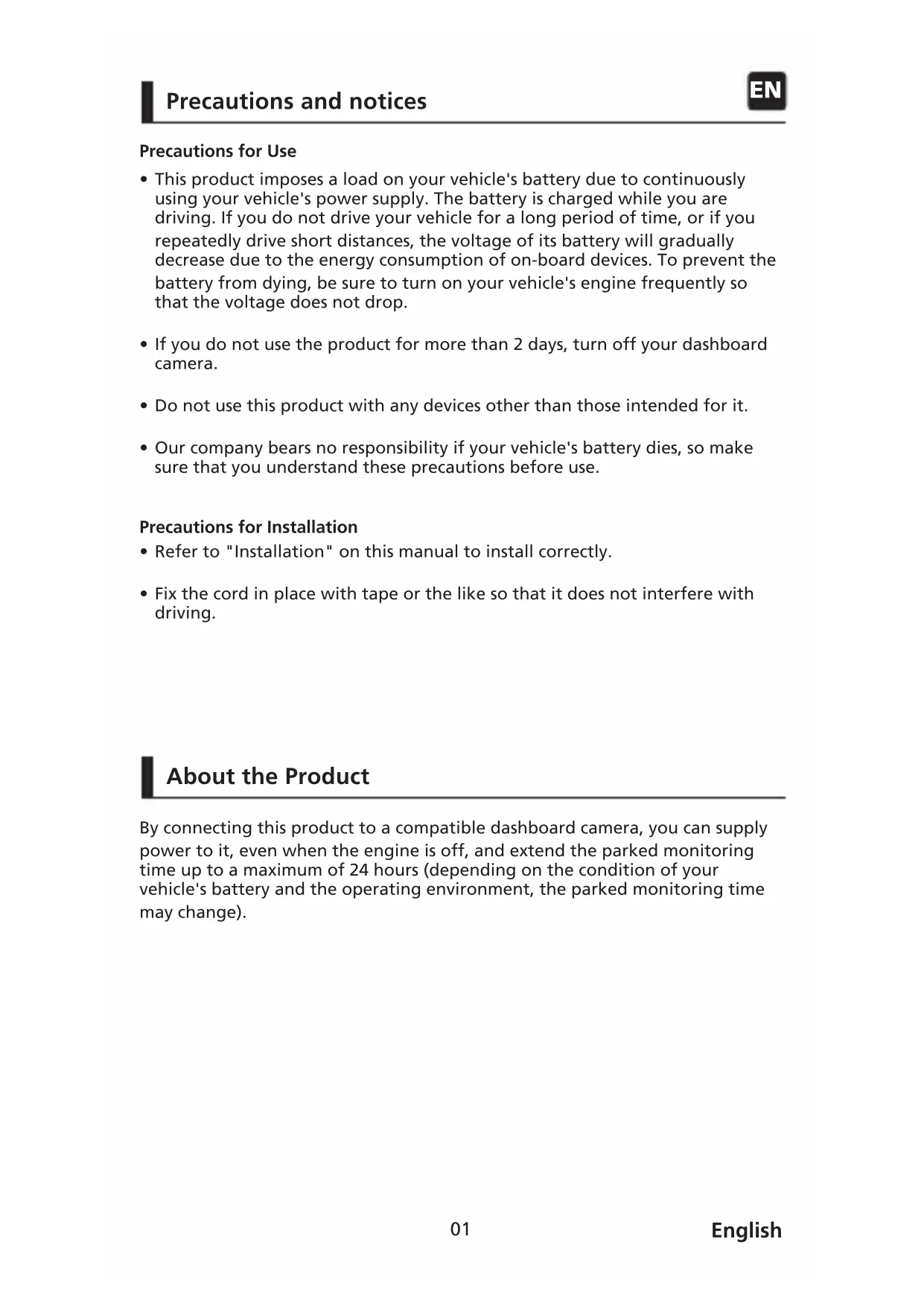
Precautions for Use
- This product imposes a load on your vehicle's battery due to continuously using your vehicle's power supply. The battery is charged while you are driving. If you do not drive your vehicle for a long period of time, or if you repeatedly drive short distances, the voltage of its battery will gradually decrease due to the energy consumption of on-board devices. To prevent the battery from dying, be sure to turn on your vehicle's engine frequently so that the voltage does not drop.
- If you do not use the product for more than 2 days, turn off your dashboard camera.
- Do not use this product with any devices other than those intended for it.
- Our company bears no responsibility if your vehicle's battery dies, so make sure that you understand these precautions before use.
Precautions for Installation
- Refer to "Installation" on this manual to install correctly.
- Fix the cord in place with tape or the like so that it does not interfere with driving.
About the Product
By connecting this product to a compatible dashboard camera, you can supply power to it, even when the engine is off, and extend the parked monitoring time up to a maximum of 24 hours (depending on the condition of your vehicle's battery and the operating environment, the parked monitoring time may change).
Accessories
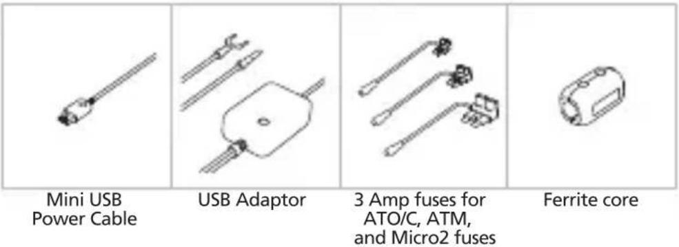
Before you get started, check you have everything below.
text_image
Mini USB Power Cable USB Adaptor 3 Amp fuses for ATO/C, ATM, and Micro2 fuses Ferrite core* Product appearance may differ slightly from that shown above.
Parts Name
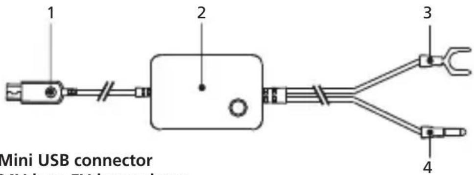
Power Cable
text_image
1 2 3 4 Mini USB connector MX into FXI connectors1.5V Mini USB connector
2. 12-24Vdc to 5Vdc regulator.
3. Negative (-) spade connector.
4. Positive (+) car power cable bullet connector.
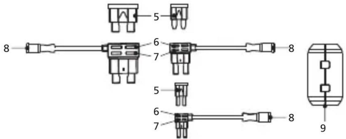
Fuse Tap Cables
text_image
5 6 7 8 5 6 7 8 9- ATO/C, ATM & Micro2 2Amp fuses.
- The socket for 2 Amp fuse tap cable.
- The socket for the original fuse.
- Positive (+) fuse tap cable bullet connector.
- Ferrite Core
Step 1: Connect the Fuse Tap Cable to the fuse box.
1.1 Find your vehicle's fuse box. Typically it locates under the driver steering wheel or underneath your engine hood. Please refer your vehicle manual.
1.2 Remove an original fuse associated with your vehicle's ignition ACC/Switched or Permanent power supply. We recommend that the maximum rating of the fuse is no more than 20 Amps. Please refer your vehicle manual.
1.3 There is a 2 Amp fuse (Item 5) built in the socket for 2 Amp fuse tap cable (Item 6) which protects the dash cam. Please do not remove or change it.
1.4 Choose the correct fuse tap cable from the three supplied types. Plug in the original fuse to the socket for the original fuse (Item 7). Plug in the Fuse Tap Cable to the socket where the original fuse was removed from the fuse box on Step 1.2.
Step 2: Car Power Cable Installation
2.1 Mount the dash cam behind the rearview mirror and connect the 5V Mini USB connector (Item 1) to the dash cam.
2.2 Beginning with the dash cam end, tuck the car power cable into the headliner and hide the power cable along the A-pillar to the rubber trim by using a pry/trim removal tool to loosen any trim. Make sure there is still enough cable for dash cam connections.
2.3 Keep lining the cable to the fuse box. Once you have the cable to the fuse box, look for the ground around the area of the fuse box. We recommend you ground the negative(-) spade connector (Item 3) to a bolt on unpainted bare metal. Next, plug in the positive(+) car power bullet connector (Item 4) to the positive(+) fuse tap cable bullet connector (Item 8), and it will enable the dash cam to receive power. Organize any excess cable by using a cable clip to a convenient position.
2.4 If required, we've included a Ferrite Core(Item 9) along with the Hardwire Kit. This can be used to suppress any radio electronic interference. Loop it around the Power Cable about 5-8 inches from the dash cam for best result.
Specifications
| Cable Length | 4m, 13ft |
| Connector Type | Mini USB |
| Input | DC12V/24V ——2A |
| Output | 5V ——2A |
| Weight | 5.5oz / 157g |
natural_image
Four technical line drawings of electronic components or connectors, no text or symbols presentInformation on Disposal of Old Electrical and Electronic Equipment (applicable for countries that have adopted separate waste collection systems)
Products with the symbol (crossed-out wheeled bin) cannot be disposed of as household waste.
Old electrical and electronic equipment should be recycled at a facility capable of handling these items and their waste by products.
Contact your local authority for details in locating a recycle facility nearest to you.
Proper recycling and waste disposal will help conserve resources while preventing detrimental effects on our health and the environment.

Declaration of Conformity with regard to the EMC Directive 2014/30/EU
Declaration of Conformity with regard to the RoHS Directive 2011/65/EU
Manufacturer:
JVCKENWOOD Corporation
3-12, Moriyacho, Kanagawa-ku,
Yokohama-shi, Kanagawa 221-0022, JAPAN
EU Representative:
JVCKENWOOD Europe B.V.
Amsterdamseweg 37, 1422 AC UITHOORN, THE NETHERLANDS
3-12, Moriyacho, Kanagawa-ku,
Yokohama-shi, Kanagawa 221-0022, JAPON
3-12, Moriyacho, Kanagawa-ku,
Yokohama-shi, Kanagawa 221-0022, JAPAN
EU-Vertreter:
JVCKENWOOD Europe B.V.
Amsterdamseweg 37, 1422 AC UITHOORN, NIEDERLANDE
3-12, Moriyacho, Kanagawa-ku,
Yokohama-shi, Kanagawa 221-0022, JAPAN
3-12, Moriyacho, Kanagawa-ku,
Yokohama-shi, Kanagawa 221-0022, JAPAN
Rappresentante UE:
JVCKENWOOD Europe B.V.
Amsterdamseweg 37, 1422 AC UITHOORN, PAESI BASSI
3-12, Moriyacho, Kanagawa-ku,
Yokohama-shi, Kanagawa 221-0022, JAPAN
3-12, Moriyacho, Kanagawa-ku,
Yokohama-shi, Kanagawa 221-0022, JAPONYA
AB Temsilcisi:
JVCKENWOOD Europe B.V.
Amsterdamseweg 37, 1422 AC UITHOORN, HOLLANDA

This equipment may generate or use radio frequency energy. Changes or modifications to this equipment may cause harmful interference unless the modifications are expressly approved in the instruction manual.
The user could lose the authority to operate this equipment if an unauthorized change or modification is made.
FCC NOTE
- This equipment has been tested and found to comply with the limits for a Class B digital device, pursuant to Part 15 of the FCC Rules. These limits are designed to provide reasonable protection against harmful interference in a residential installation.
- This equipment may cause harmful interference to radio communications, if it is not installed and used in accordance with the instructions. However, there is no guarantee that interference will not occur in a particular installation. If this equipment does cause harmful interference to radio or television reception, which can be determined by turning the equipment off and on, the user is encouraged to try to correct the interference by one or more of the following measures:
- Reorient or relocate the receiving antenna.
- Increase the separation between the equipment and receiver.
- Connect the equipment into an outlet on a circuit different from that to which the receiver is connected.
- Consult the dealer or an experienced radio/TV technician for help.
This transmitter must not be co-located or operated in conjunction with any other antenna or transmitter.
CAN ICES-3(B)/ NMB-3(B)
IC (Industry Canada) Notice
This device contains licence-exempt transmitter(s)/receiver(s) that comply with Innovation, Science and Economic Development Canada's licence-exempt RSS(s). Operation is subject to the following two conditions:
- This device may not cause interference.
- This device must accept any interference, including interference that may cause undesired operation of the device.
CAUTION
This equipment complies with FCC/IC radiation exposure limits set forth for an uncontrolled environment and meets the FCC radio frequency (RF) Exposure Guidelines and RSS-102 of the IC radio frequency (RF) Exposure rules. This equipment has very low levels of RF energy that is deemed to comply without maximum permissive exposure evaluation (MPE). But it is desirable that it should be installed and operated keeping the radiator at least 20 cm or more away from person's body.
Pour le Canada
Note de 'IC (Industrie Canada)
Supplier's Declaration of Conformity
Trade Name: KENWOOD
Products: Hardware Kit
Model Name: CA-DR1030
Responsible Party:
JVCKENWOOD USA CORPORATION
2201 East Dominguez Street,
Long Beach, CA 90810, U.S.A.
PHONE: 310 639-9000
THIS DEVICE COMPLIES WITH PART 15 OF THE FCC RULES. OPERATION IS SUBJECT TO THE FOLLOWING TWO CONDITIONS:
(1) THIS DEVICE MAY NOT CAUSE HARMFUL INTERFERENCE, AND
(2) THIS DEVICE MUST ACCEPT ANY INTERFERENCE RECEIVED, INCLUDING
INTERFERENCE THAT MAY CAUSE UNDESIRED OPERATION.