WPC 100 RO - Water purifier Kärcher - Free user manual and instructions
Find the device manual for free WPC 100 RO Kärcher in PDF.
| Product type | Water Osmosis System |
| Brand | Kärcher |
| Model | WPC 100 RO |
| Operating voltage | 110…240 V, 1~50-60 Hz |
| Connected load | 80 W |
| Minimum fuse protection | 6 A |
| Water inlet pressure | 0.1…0.3 MPa (1…3 bar) |
| Water inlet temperature | 5…45 °C |
| Filter capacity (max) | 100 L/h |
| Dimensions (L × W × H) | 372 × 240 × 530 mm |
| Weight (empty) | 13.45 kg |
| Weight in operation | 17.86 kg |
| Sound pressure level | < 60 dB(A) |
| Number of filtration stages | 5 (non-woven pre-filter, granular activated carbon, block activated carbon, reverse osmosis membrane, high-grade activated carbon) |
| Types of retained pollutants | Bacteria, chlorine, salts, heavy metals, nitrates, herbicides, drug residues, hormones, coloration |
| Bacteria retention rate | Up to 99.99 % |
| Chlorine retention rate | Up to 100 % |
| Replacement interval pre-filters | 3-6 months |
| Replacement interval activated carbon filters | 6-12 months |
| Replacement interval membranes | 18-24 months |
| Possible installation | On table, under table, wall-mounted (mounting not supplied) |
| Connections | Raw water (white tube ∅9.5 mm), clean water (blue tube ∅6.35 mm), concentrate drain (red tube ∅6.35 mm) |
| Warranty | According to conditions in force in the country |
| Spare parts | Use only genuine Kärcher parts |
Frequently Asked Questions - WPC 100 RO Kärcher
User questions about WPC 100 RO Kärcher
0 question about this device. Answer the ones you know or ask your own.
Ask a new question about this device
Download the instructions for your Water purifier in PDF format for free! Find your manual WPC 100 RO - Kärcher and take your electronic device back in hand. On this page are published all the documents necessary for the use of your device. WPC 100 RO by Kärcher.
USER MANUAL WPC 100 RO Kärcher
natural_image
3D rendering of an industrial water treatment unit with multiple cylindrical tanks and piping (no visible text or labels)Deutsch 3
English 9
Français 15
Italiano 21
Nederlands 27
Español 33
Português 39
Dansk 45
Norsk 51
Svenska 57
Suomi 63
Ελληνικά 69
Türkçe 75
Русский 81
Magyar 87
Čeština 93
Slovenščina 99
Polski 105
Românește 111
Slovenčina 117
Hrvatski 123
Srpski 129
Български 135
Eesti 141
Latviešu 147
Lietuviškai 153
Українська 159
中文 165
Register and win! www.kaercher.com/register-and-win


59671920 10/18
Inhaltsverzeichnis
- Membranfilter (Umkehrosmose)
text_image
B Q → → ✓text_image
Technical diagram of a mechanical or fluid system with labeled components and flow pathstext_image
Technical diagram of a mechanical valve assembly with numbered parts labeled 1 to 4text_image
Technical diagram of a mechanical assembly with numbered components for identificationnatural_image
Diagram of a mechanical device with a lever and internal components, showing a close-up view of the lever assembly (no text or labels)Hinweis
text_image
Technical diagram of a three-cylinder water treatment unit with labeled componentsnatural_image
Mechanical assembly diagram showing two cylindrical components with black arrows indicating motion or force direction (no text or symbols)natural_image
3D rendered mechanical components with cylindrical and curved arms, no visible text or symbolsnatural_image
3D mechanical assembly diagram showing a robotic arm with directional arrows indicating motion or force (no text or symbols)natural_image
Mechanical assembly diagram showing two black arrows pointing to a cylindrical component mounted on a metal frame (no text or symbols)natural_image
Mechanical assembly diagram showing internal components with no visible text or symbolsnatural_image
Illustration of a water treatment machine with cylindrical tanks and a hand holding a tool, accompanied by a separate schematic diagram (no text or labels)natural_image
3D rendered mechanical assembly with cylindrical components and mounting brackets (no text or symbols visible)natural_image
3D mechanical assembly diagram showing two cylindrical components and a fan-like structure with curved blades (no text or symbols)natural_image
Illustration of a tool applying force to a threaded component, showing mechanical assembly (no text or symbols)
Chairman of the Board of Management

S. Reiser
Director Regulatory Affairs & Certification
71364 Winnenden (Germany)
Tel.: +49 7195 14-0
Fax: +49 7195 14-2212
Verbrauchsmaterial
Environmental protection EN 1
Warranty EN 1
Spare parts EN 1
| Proper use | EN 2 |
| Types of contamination. . . . . . EN 2 | |
Function EN 2
| Connecting the appliance | EN 2 |
| Selecting the setup location ... EN 2 | |
Water connection ..... EN 2
Quick connectors – basics .... EN 2
Connecting the appliance ..... EN 2
Connection to untreated water line EN 2
Connection to untreated water line EN 2
Installing the filtered water tap. EN 3
| Start up | EN 3 |
| Initial startup | EN 3 |
Preparing filters for start-up ... EN 3
Rinsing out the three lower filters
(pre-filters) ...... EN 3
Rinsing the membrane filters (re-
verse osmosis)....EN 3
Operation EN 3
Shutdown EN 3
Startup after shutdown EN 3
Using in a Kärcher WPD EN 3
Installing in a Kärcher WPD unit EN 3
Initial start-up of Kärcher WPD unit EN 3
Removing WPC 100 RO from a
Kärcher WPD unit ..... EN 3
Dispensing water from a Kärcher
WPD unit..... EN
Care and maintenance EN 4
Maintenance instructions ..... EN 4
Maintenance contract ..... EN 4
Replacing filter inserts.....EN 4
Replacing pre-filter inserts .... EN 4
Replacing membrane filter (reverse
osmosis) inserts EN
Replacing activated carbon filter EN 4
EU Declaration of Conformity EN 4
Consumables EN 5
Filter replacement intervals EN 5
Troubleshooting EN 5
Technical specifications EN 6
Degree of retention EN 6
Safety
Danger or hazard levels
⚠️DANGER
Pointer to immediate danger, which leads to severe injuries or death.
⚠ WARNING
Pointer to a possibly dangerous situation, which can lead to severe injuries or death.
△CAUTION
Pointer to a possibly dangerous situation, which can lead to minor injuries.
ATTENTION
Pointer to a possibly dangerous situation, which can lead to property damage.
Safety instructions
⚠️DANGER
Risk of electric shock!
→ First remove the mains plug before doing any job on the device.
→ If the mains cable or mains plug are damaged, they must be replaced by trained personnel.
⚠ WARNING
Health hazards on account of improperly repaired device.
→ The appliance may only be repaired by trained and skilled personnel.
⚠ WARNING
Health risk due to the contamination with germs.
→ Existing, old hose-sets should not be used. The new hose-sets, supplied with the appliance, should be used.
→ When replacing the filter cartridges, ensure hygiene and cleanliness.
→ Wear sterile disposable gloves when replacing the filter.
⚠ WARNING
Be sure to use the correct filters during a change.
→ Always insert the filters in the correct position.
General notes
■ Only slightly dirty water or drinking water from an unknown or unsafe source can be used to guarantee the water quality of the emerging water. The unit can also be connected to the drinking water network of the public water supply to ensure the quality of the drinking water up to the tap.
If the drinking water supply must be tapped to install the appliance, this must be performed by trained expert personnel that is in possession of a permit that meets the local laws and regulations. This work must be ordered by the customer if required.
■ To protect from water damage caused by a burst water supply hose, we recommend the installation of a Shut-off-valve and an aqua stop (sold separately) in the water supply line.
■ Do not clean the device with a water stream.
■ Plastic surfaces must not be cleaned with alcohol-containing, aggressive or abrasive detergents. The surface cleaner CA 30 R (6.295-686.0) is recommended.
■ After initial start-up, filter changes and long periods of disuse, dispensed water may temporarily be milky in appearance. This is due to small air bubbles in the water and does not affect water quality.
Environmental protection
Notes about the ingredients (REACH)
You will find current information about the ingredients at:
www.kaercher.com/REACH
The packaging material can be recycled. Please arrange for the environmentally appropriate disposal of the packaging.
Electrical and electronic devices often contain components which could potentially pose a danger to human health and the environment if handled or disposed of incorrectly. However, these components are necessary for the proper operation of the device. Devices marked with this symbol must not be disposed of with regular household rubbish.
Old appliances contain valuable recyclable materials that should be recycled properly. Batteries and accumulators contain substances that must not enter the environment. Please dispose of old devices and batteries or accumulators in an environmentally friendly way.
Warranty
The warranty terms published by the relevant sales company are applicable in each country. We will repair potential failures of your appliance within the warranty period free of charge, provided that such failure is caused by faulty material or defects in manufacturing. In the event of a warranty claim please contact your dealer or the nearest authorized Customer Service centre. Please submit the proof of purchase.
Spare parts
■ Only use accessories and spare parts which have been approved by the KÄRCHER. The exclusive use of original accessories and original spare parts ensures that the appliance can be operated safely and troublefree.
■ For additional information about spare parts, please go to the Service section at www.kaercher.com.
Proper use
The unit is designed to convert untreated water (waste water) into drinking water.
Types of contamination
Untreated water may be contaminated by:
- B a c t e r i a
- Chlorine
– Salts (for example: sodium, potassium, calcium)
- Aluminium
- A r s e n i c
- Heavy metals (for example: lead)
- Nitrate
– Herbicides (glyphosate)
– Pharmaceutical residues
- Hormone residues
- Colouring
The quality of the drinking water produced ultimately depends on the degree of contamination of the untreated water.
Adequate untreated water quality must be ensured.
Clean drinking water can only be achieved through regular maintenance of all filters belonging to the unit.
■ Before using the unit for the first time, we recommend analysing the untreated water in accordance with Directive 98/83/EC Annex 3 "Indicator Parameters".
■ An analysis of untreated water is not necessary to operate the unit.
■ Drinking water quality is only guaranteed if the unit is checked regularly.
■ The unit is designed to be connected to the water line.
■ Any national drinking water regulations must be observed.
■ The unit is not designed for use as a sewage treatment system.
■ The unit is not suitable for seawater softening.
This device is not intended for use by persons (including children) with reduced physical, sensory or mental abilities or lacking experience and/or knowledge, unless they are supervised by a person responsible for their safety or are instructed by these persons on the use of the device. Children should be supervised, to ensure that they do not play with the device.
■ The appliance may not be set up and used in commercial kitchens.
■ The appliance must be installed in frost-free rooms.
■ Do not use or park the device outdoors.
■ The unit can also be used as a pre-filter in a Kärcher WPD water dispenser.
When used as intended, water produced from this unit can be classified as drinking water.
Function
Water flows from the water inlet through the following filters:
– Fleece filter (removes large particles of dirt)
- Activated carbon filter (granulate)
- Activated carbon filter (block)
– Membrane filters (reverse osmosis)
- Activated carbon filter (ensures neutral taste)
The entire filtration system must be replaced at regular intervals.
Connecting the appliance
During initial installation and any repairs that involve the replacement of accessory parts, make sure only the enclosed parts are used. These parts are components that have been approved by KÄRCHER for installation. Never use other components.
■ The power connection and the water input pressure must conform to the data in the specifications.
■ Depending on local regulations, the installation of an approved check-valve is required.
■ There must be an even surface available to install the appliance.
■ The unit is suitable for wall mounting.
→ For wall mounting, use the openings in the frame.
The fastening material for the wall-mounted installation is not included in the scope of delivery and must be procured in accordance with the conditions on site.
→ When mounting on the wall, check the load capacity of the wall.
■ Power plug and receptacle must be freely accessible after the installation.
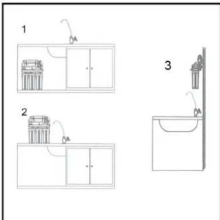
Selecting the setup location
text_image
1 2 31 Under-sink installation
2 Mounting on a table
3 Wall m o u n t
Note
When selecting an installation location, make sure connections and stop valves remain easily accessible. Leave enough room for filter changes. Hose lines should be placed so that they do not bend.
Water connection
When connecting to the drinking water supply, observe local regulations on disconnecting from the mains.
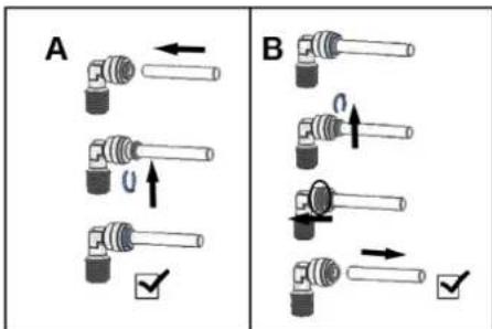
Quick connectors – basics
text_image
A BA Attaching hose
B Removing hose
→ Cut hose to length before insertion.
Note
Cut hose straight across. Hoses cut at an angle cause leaks.
Connecting the appliance
Note
Before connecting, select an installation location and cut the hose lines to length accordingly. Make sure to leave enough hose in case the unit has to be moved (e.g. when changing the filters).
For easy identification, the hose lines are colour coded and have different diameters:
| Blue Filtered water outlet from unit, d = 6.35 mm |
| White Supply from water main, d = 9.5 mm |
| Red Drain water line (concentrate), d = 6.35 mm |
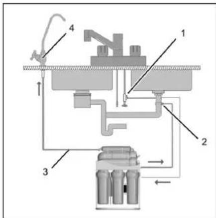
text_image
Technical diagram of a mechanical or fluid system with labeled components and flow paths1 T-piece to untreated water line
2 Drain water line (concentrate)
3 Fresh water outlet (filtered water)
4 Filtered water tap
Connection to untreated water line
ATTENTION
Risk of water damage. During installation, make sure all connections are secure and check for leaks. In case of doubt, consult an expert.
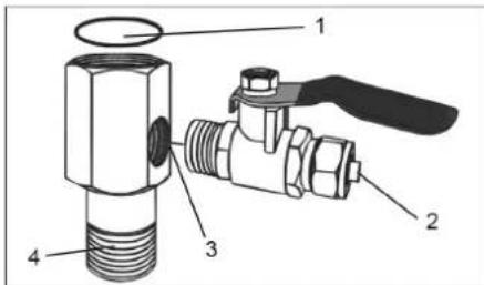
text_image
Technical diagram of a valve assembly with numbered parts labeled 1 to 41 O-ring, outlet seal
2 Outlet to WPC 100 RO
3 Stop cock connection
4 Untreated water line connection
Note
Inlet and outlet thread: 1/2"
→ Screw the stop cock into the connection piece, use sealing tape.
→ Insert the T-piece into the untreated water line.
→ Use an O-ring on the outlet and sealing tape on the inlet.
→ Insert hose (white) into the T-piece and secure.
→ Insert hose (white) into the untreated water inlet of the unit and secure.
Connection to untreated water line
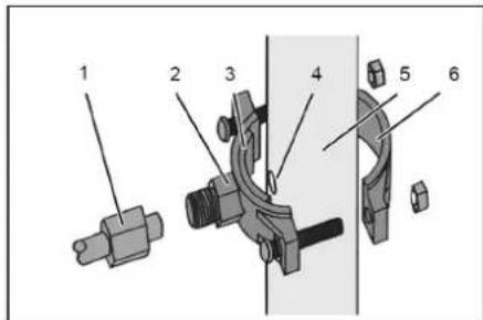
text_image
Technical diagram of a mechanical assembly with numbered components for identification1 Drain water line (concentrate) fitting
2 Drain water outlet pipe clamp (front half)
3 Sealing piece (self-adhesive)
4 Hole (d = 6 mm).
5 Wastewater pipe to sewer system
6 Drain water outlet pipe clamp (rear half)
→ Mark and drill the hole (d = 6 mm).
Note
Only drill the hole on one side. Do not drill through the pipe. The pipe clamp can be used as a drill jig.
→ Attach sealing piece to the pipe clamp.
→ Insert hose (red) into the fitting.
→ Fasten pipe clamp to the drain water line as shown above.
→ Fasten hose (red) with pipe clamp.
→ Insert hose (red) into the drain water outlet of the unit and secure.
Note
The hole has a smaller diameter than the hose (red). This causes the hose to contact the sides of the drain water pipe. The hose should not protrude into the drain water pipe. The self-adhering sealing piece provides a seal.
Installing the filtered water tap
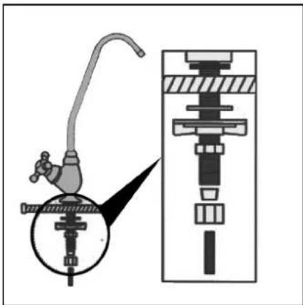
natural_image
Diagram of a mechanical device with a faucet and internal components, showing a close-up view of the shaft (no text or labels)Note
The filtered water tap should be installed over a basin connected to the sewage drain.
→ Install filtered water tap as shown.
→ Hole diameter: 12-15 mm
→ Make sure the individual parts are arranged correctly during installation.
→ Connect hose line to the filtered water outlet of the unit.
→ Connect hose line to the filtered water tap. Alternatively, the filtered water tap can be mounted directly to the wall using the included mounting bracket.
Start up
Initial startup
The system should be filled and rinsed out before dispensing water for drinking.
△WARNING
Health risk due to the contamination with germs.
Pay attention to hygiene and cleanliness when inserting and removing filter cartridges.
Do not touch the connections of the socket and filters. Wear disposable gloves when inserting filters.
Do not damage the seals during installation and removal.
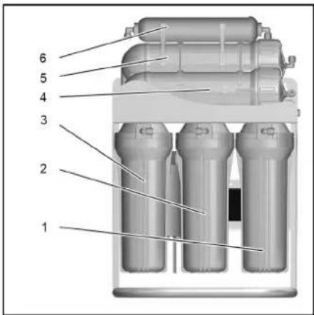
The unit consists of three filter groups:
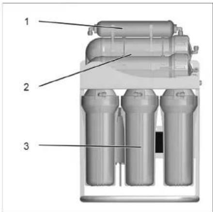
text_image
Technical diagram of a three-cylinder water treatment unit with labeled components1 Upper activated carbon filter
2 Membrane filters (reverse osmosis)
3 Lower filter group (pre-filter)
Preparing filters for start-up
→ Loosen the three filter chambers of the lower filter group using the included spanner (black).
→ Unscrew filter chambers.
→ Remove filter inserts from the filter chambers and remove the protective film.
→ Screw on filter chamber with filter insert and hand-tighten.

natural_image
Mechanical assembly diagram showing fluid flow paths with arrows indicating direction (no text or symbols)→ Remove the supply hoses from the membrane filters and run them out of the sides of the unit into a suitable container.

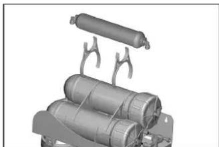
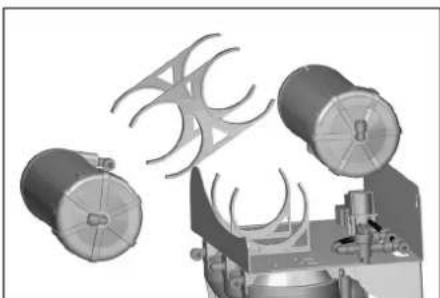
natural_image
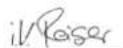
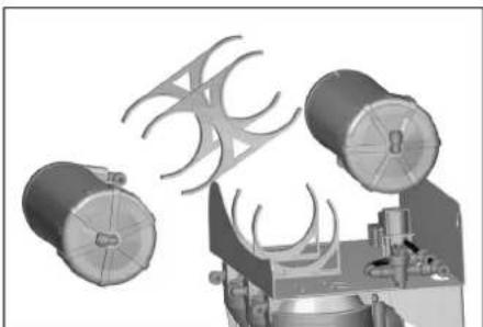
3D rendered mechanical components with cylindrical bodies and support brackets (no text or symbols)→ Remove the upper activated carbon filter.
→ Remove the membrane filter chambers from the bracket one at a time.
→ Unscrew and remove cap with included spanner (black).
→ Remove filter inserts (membrane filters) from the packaging and remove the protective film.
→ Insert filter inserts into the filter chambers as far as they will go.
→ Screw on the cap and hand-tighten.
→ Place filter chambers in the brackets.
→ Do not reconnect the supply hoses yet.
→ Insert the upper activated carbon filter.
→ Connect hoses (blue and red) for filtered water and drain water concentrate to the outlets on the unit.
Rinsing out the three lower filters (pre-filters)
→ Connect the unit to the water main.
→ Make sure the two supply hoses for the membrane filters are running to a suitable container (min. 10 litres).
→ Turn on filtered water tap.
The system begins filling with water.
→ Plug in the mains plug.
→ Rinse the system for at least five minutes to remove air and any production residue from the pre-filters.
→ Pull out the mains plug.
→ Turn off filtered water tap.
→ Dispose of the water in the container.
Rinsing the membrane filters (reverse osmosis)
→ Take supply hoses out of the container and re-connect them to the membrane filters.
natural_image
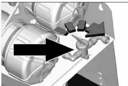
3D mechanical assembly diagram showing components and directional arrows (no text or labels)→ Open the bypass valve.
→ Connect hoses (red and blue).
→ Turn on filtered water tap.
→ Plug in the mains plug.
The system begins filling with water.
The water will initially flow primarily out of the red hose for drain water concentrate. This is normal.
→ Rinse the system for at least five minutes to remove air and any production residue from the membrane filters.
→ Close the bypass valve.
Water will now flow out of both hoses (red and blue).
→ Rinse the system for another five minutes.
→ Turn off filtered water tap.
→ Pull out the mains plug
The unit is now ready for use.
Operation
→ Turn on filtered water tap to dispense filtered water.
Shutdown
If the appliance will not be needed for more than 4 days:
→ Shut off water supply.
→ Pull out the mains plug.
Startup after shutdown
△WARNING
Health risk due to increased micro-organism concentration in the water.
→ Changing filter cartridges
→ Rinse out the unit
Using in a Kärcher WPD
Installing in a Kärcher WPD unit
Kärcher WPD units come with the WPC 100 RO installed.
The unit cannot be used in a WPD 100 with carbonating function.
Kärcher Customer Service connects all hoses and performs initial start-up.
Note
Should it be necessary to open the side parts for the installation and initial startup of the device, this may only be done by a qualified electrician.
Initial start-up of Kärcher WPD unit
The WPD unit is required for initial start-up. Before initial start-up in the WPD unit, the WPC 100 must be rinsed out and prepared as described in the section "Initial start-up".
Initial start-up of the WPD drinking water dispenser is described in the unit's operating manual.
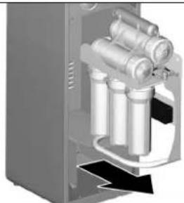
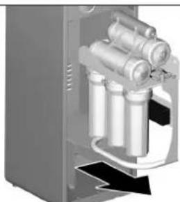
Removing WPC 100 RO from a Kärcher WPD unit
Note
A factory-installed WPC 100 RO must be removed from the WPD base before changing filters.
→ Shut off water supply.
→ Unpressurize the appliance: Press all buttons for different types of beverages briefly until the system is unpressurized. Avoid the appliance running dry.
→ Switch off the appliance using the On/Off switch
→ Disconnect the mains plugs (WPD and WPC).
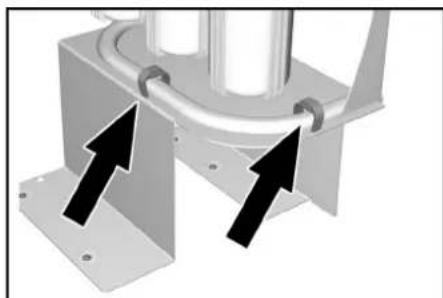
natural_image
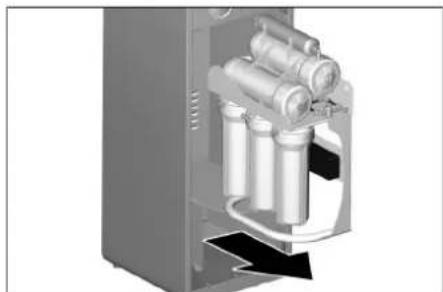
Mechanical assembly diagram showing two black arrows pointing to a pipe fitting (no text or symbols present)→ Open the Velcro strips.
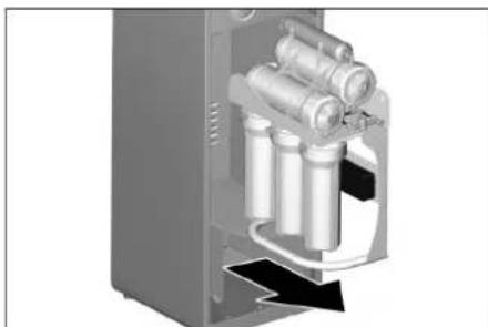
natural_image
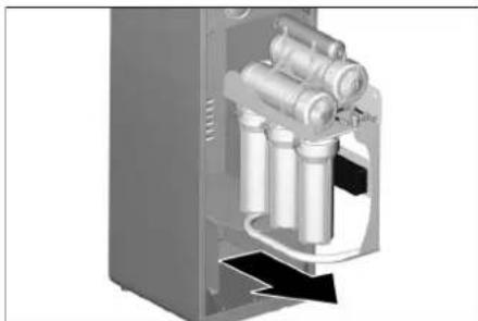
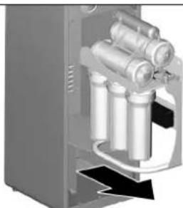
3D rendering of a mechanical device with cylindrical components and a black arrow indicating direction (no text or symbols)→ Remove the filter unit and set it in front of the unit.
→ Filter change, see chapter "Care and maintenance / Replacing filter inserts"
→ After the filter change, reassemble the unit in the reverse order.
Dispensing water from a Kärcher WPD unit
Operation of the WPD drinking water dispenser is described in the unit's operating manual.
Care and maintenance
Maintenance instructions
△WARNING
Health hazards on account of improperly repaired appliance. The appliance may only be repaired by trained and skilled personnel.
Use only original parts of the manufacturer or part suggested by him, such as
- parts and wearing parts,
- accessories parts,
- operating materials,
- cleaning agents.
Before doing any work on the machine:
→ Shut off water supply.
→ Turn on the filtered water tap to depressurise the unit.
→ Pull out the mains plug.
Maintenance contract
In order to ensure a reliable operation of the device, we recommend that you conclude a maintenance contract. Please contact your competent KÄRCHER service.
Replacing filter inserts
The filters installed in the unit must be replaced at regular intervals. This interval depends on use. An overview of the recommended filter replacement intervals can be found at the end of these instructions.
△WARNING
Health risk due to the contamination with germs. When replacing the filter cartridges, ensure hygiene and cleanliness.
Do not touch the connections of the socket and filters. Wear disposable gloves when replacing a filter. Do not damage the seals during installation and removal.
Note
Used filters can be thrown away with household rubbish.
text_image
1 2 3 4 5 61 Fine filter
2 Activated carbon filter (granulate)
3 Activated carbon filter (block)
4 Membrane filter 1 (reverse osmosis)
5 Membrane filter 2 (reverse osmosis)
6 Active carbon filter
Replacing pre-filter inserts
ATTENTION
Risk of water damage. The filter chambers are full of water. Place a suitable container or dish underneath before removal.
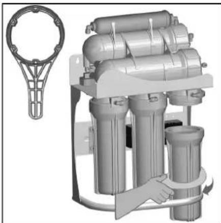
natural_image
Illustration of a water treatment machine with a hand adjusting its components (no text or symbols visible)→ Unscrew the filter chambers using the included black spanner.
→ Replace the filter.
Note
Filters must be installed in the same position and must not be interchanged! Observe the illustration.
Make sure the seals are seated properly during installation.
Only hand-tighten filter chambers using the included black spanner.
Replacing membrane filter (reverse osmosis) inserts
ATTENTION
Risk of water damage. The membrane filter chambers are full of water. Place a suitable container or dish underneath before removal.
→ Disconnect the hose connections and remove the hoses.
natural_image
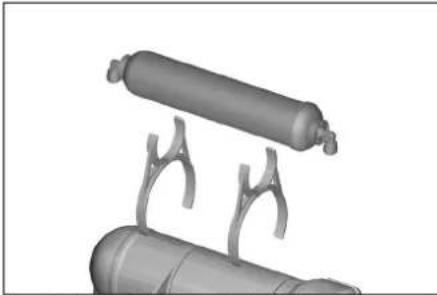
3D rendered mechanical assembly with cylindrical components and mounting brackets (no text or symbols visible)→ Remove the upper activated carbon filter.

natural_image
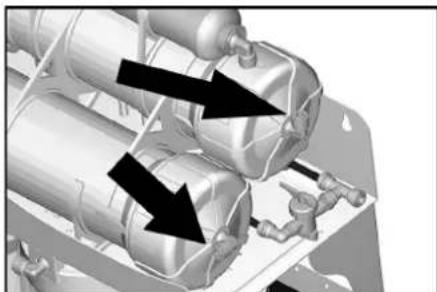
3D mechanical assembly diagram showing two cylindrical components and a base with curved blades (no text or symbols)→ Remove the membrane filters from the brackets.
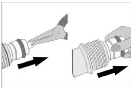
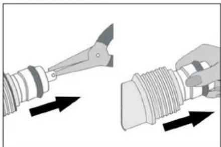
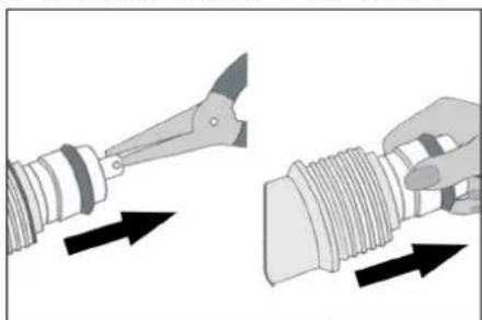
→ Unscrew cap using the included white spanner.
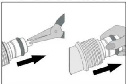
natural_image
Illustration of a tool applying force to a threaded component, showing mechanical assembly (no text or symbols)→ Use a tool to carefully loosen membrane insert.
→ Carefully pull membrane insert out of casing by hand.
→ Insert new membrane insert.
→ Screw cap back on.
→ Insert membrane filter into the bracket.
→ Reconnect hoses.
Replacing activated carbon filter
Note
The upper activated carbon filter at the end of the filtration system does not have a filter insert and must be replaced in its entirety.
→ Disconnect the hose connections and remove the hoses.
→ Remove the upper activated carbon filter.
→ Install new activated carbon filter.
→ Reconnect hoses.
EU Declaration of Conformity
We hereby declare that the machine described below complies with the relevant basic safety and health requirements of the EU Directives, both in its basic design and construction as well as in the version put into circulation by us. This declaration shall cease to be valid if the machine is modified without our prior approval.
Product: Water treatment plant Type: 1.024-xxx
Relevant EU Directives
2014/35/EU
2014/30/EU
2011/65/EU
Applied harmonized standards
EN 60335-1
EN 62233: 2008
EN 55014-1:2006+A1:2009+A2:2011
EN 55014-2: 2015
EN 61000-3-2: 2014
EN 61000-3-3: 2013
EN 50581
Applied regulations
[Non-Text]
The signatories act on behalf of and with the authority of the company management.
Chairman of the Board of Management
S. Reiser
Director Regulatory Affairs & Certification
Documentation supervisor: S. Reiser
Alfred Kärcher SE & Co. KG
71364 Winnenden (Germany)
Tel.: +49 7195 14-0
Fax: +49 7195 14-2212
Consumables
| Description Description Order No. | ||
| Fine filter First stage of filtration for separation of coarse dirt particles 6.640-765.0 | ||
| Activated carbon filter (granulate) | Second stage of filtration for pre-separation of harmful substances | 6.640-766.0 |
| Activated carbon filter (block) | Third stage of filtration for fine separation of harmful substances | 6.640-767.0 |
| Membrane filters (reverse osmosis) Fourth stage of filtration for desalination 6.640-783.0 | ||
| Upper activated carbon filter Fifth stage of filtration for ensuring neutral taste after reverse osmosis 6.640-769.0 | ||
Filter replacement intervals
| Fine filter 3 - 6 | months or as needed (see Section "Troubleshooting") | |
| Activated carbon filter (granulate) 6 - 12 | ||
| Activated carbon filter (block) | 6 - 12 | |
| Membrane filters (reverse osmosis) | 18 - 24 | |
| Active carbon filter | 6 - 12 |
Troubleshooting
| FailureNo water dispensed | Possible causeMains Plug not connected to the socket. | CorrectionPlug in the mains plug. |
| Water supply not connected | Connect to water supply. | |
| Pressure switch on unit not working | Contact service. | |
| Solenoid valve is defective | Contact service. | |
| Little water dispensed | The pump does not run | Check pump. |
| Bypass valve open | Close the bypass valve. | |
| Fine filter blocked. | Replace fine filter. | |
| Membrane filter (reverse osmosis) blocked. | Replace membrane filter (reverse osmosis). | |
| Pump does not stop | Pressure switch on unit not working. | Contact service. |
| Pump does not start. | Pressure switch on unit not working. | Contact service. |
| Fine filter blocked. | Replace fine filter. | |
| Pressure switch inlet defective. | Contact service. | |
| Water supply not connected | Check water supply. | |
| Mains Plug not connected to the socket. | Plug in the mains plug. | |
| Pump defective. | Contact service. | |
| Water leaking from filter chamber | Filter chamber loose. | Tighten filter chamber. |
| Filter chamber gasket not in place or defective | Check gasket, reposition, replace if damaged. | |
| Water coming from drain water line only | Bypass valve open. | Close the bypass valve. |
| Membrane filter (reverse osmosis) blocked. | Replace membrane filter (reverse osmosis). | |
| Pump defective. | ||
| Filtered water has noticeable taste | Upper activated carbon filter needs replacing. | Replace upper activated carbon filter. |
| Pump stops and restarts after a short period. | Leak / water loss / pressure loss in the unit or in the following line system. | Tighten filter casing. |
| Close off the tap completely. | ||
| Look for the cause of the leak and eliminate it. | ||
| Check valve in unit not working | Contact service. |
Technical specifications
| WPC 100 RO | ||
| Operating voltage V/~/Hz 110...240/1/50-60 | ||
| Connected load W80 | ||
| Minimum power protection A6 | ||
| Water input pressure MPa (bar) 0.1...0.3 (1...3) | ||
| Water supply temperature °C 5...45 | ||
| Filter capacity l/h 70 | ||
| Filter capacity (max) l/h 100 | ||
| Ambient temperature °C 5...45 | ||
| Width | mm | 372 |
| Depth | mm | 240 |
| Height | mm | 530 |
| Weight (empty) | kg | 13.45 |
| Operating weight (with accessories and filled with water) | kg | 17.86 |
| Sound pressure level during normal operation | dB(A) | < 60 |
| Materials / approvals | All components containing drinking water are suited for the use in direct contact with drinking water in accordance with generally accepted industry standards. | |
Degree of retention
The degree of retention of harmful substances, biological pathogens and contamination can be determined using the following table (approximate values). The actual retention capacity depends on the degree of contamination.
| Bacteria | Degree of retention up to | 99.99% |
| Chlorine | Degree of retention up to | 100% |
| Salts (sodium, potassium, calcium...) | Degree of retention up to | 90% |
| Aluminium | Degree of retention up to | 98% |
| Arsenic | Degree of retention up to | 88% |
| Heavy metals (for example: lead) | Degree of retention up to | 99% |
| Nitrate | Degree of retention up to | 50% |
| Herbicides (glyphosate) | Degree of retention up to | 60% |
| Residue of medicines | Degree of retention up to | 99.9% |
| Hormone residues | Degree of retention up to | 99.95% |
| Colouring | Degree of retention up to | 100% |
Table des matières
www.kaercher.com/REACH
text_image
Technical diagram of a mechanical or fluid system with labeled components and flow pathstext_image
Technical diagram of a mechanical valve assembly with numbered parts labeled 1 to 4text_image
Technical diagram of a mechanical assembly with numbered components for identificationnatural_image
Technical diagram of a mechanical device with a lever and internal components, showing no text or symbols.Remarque
text_image
Technical diagram of an internal water treatment device with labeled componentsnatural_image
Mechanical assembly diagram showing three cylindrical components with black arrows indicating motion direction (no text or symbols)natural_image
3D rendered mechanical components with cylindrical and curved arms (no text or symbols)natural_image
3D rendered mechanical assembly with arrows indicating motion or force direction (no text or symbols)natural_image
Mechanical assembly diagram showing two black arrows pointing to a cylindrical component mounted on a metal frame (no text or symbols)natural_image
3D cutaway view of a mechanical device showing internal components and housing (no text or symbols visible)natural_image
Illustration of a water treatment machine with multiple cylindrical tanks and a hand holding a handle (no text or symbols visible)natural_image
3D rendered mechanical assembly with cylindrical components and mounting brackets (no text or symbols visible)natural_image
3D mechanical assembly diagram showing two cylindrical components connected to a base with curved blades (no text or symbols)natural_image
Illustration of two mechanical components: a tool and a threaded component, with arrows indicating direction (no text or symbols)
Chairman of the Board of Management
S. Reiser
Director Regulatory Affairs & Certification
Responsable de la documentation : S. Reiser
Alfred Kärcher SE & Co. KG
71364 Winnenden (Germany)
Tel.: +49 7195 14-0
Fax: +49 7195 14-2212
www.kaercher.com/REACH
text_image
Technical diagram of a mechanical or fluid system with labeled components and flow pathstext_image
Technical diagram of a mechanical valve assembly with numbered parts labeled 1 to 4text_image
Technical diagram of a mechanical assembly with numbered components for identificationnatural_image
Diagram of a mechanical device with a lever and internal components, showing a close-up view of the lever assembly (no text or labels)Nota
natural_image
3D mechanical assembly diagram showing fluid flow paths with arrows indicating direction (no text or symbols)natural_image
3D rendered mechanical components with curved brackets, no visible text or symbolsnatural_image
3D mechanical assembly diagram showing internal components and directional arrows (no text or symbols)natural_image
Mechanical assembly diagram showing two black arrows pointing to a cylindrical component mounted on a metal frame (no text or symbols visible)natural_image
3D cutaway view of a mechanical device showing internal components and housing (no text or symbols visible)natural_image
Illustration of a water treatment machine with multiple cylindrical tanks and a hand adjusting one (no text or symbols visible)natural_image
3D rendered mechanical assembly with cylindrical components and mounting brackets (no text or symbols visible)natural_image
3D mechanical assembly diagram showing two cylindrical components and a fan-like structure (no text or symbols)natural_image
Illustration of a tool interacting with a threaded component, showing directional arrows (no text or symbols)
Chairman of the Board of Management
S. Reiser
Director Regulatory Affairs & Certification
71364 Winnenden (Germany)
Tel.: +49 7195 14-0
Fax: +49 7195 14-2212
Membraanfilters spoelen (omkeeros-
mose) NL 3
Bediening NL 3
Stillegging NL 3
text_image
Technical diagram of a mechanical or fluid system with labeled components and directional arrows indicating flow or movement.text_image
Technical diagram of a mechanical valve assembly with numbered parts labeled 1 to 4text_image
Technical diagram of a mechanical assembly with numbered components for identificationnatural_image
Technical diagram of a mechanical device with a lever and internal components, showing no text or symbols.Instructie
text_image
Technical diagram of a three-cylinder water treatment device with labeled componentsnatural_image
Mechanical assembly diagram showing three cylindrical components with black arrows indicating motion direction (no text or symbols)natural_image
3D rendered mechanical components with cylindrical and curved arms (no text or symbols)natural_image
3D mechanical assembly diagram showing internal components and a large black arrow indicating direction (no text or symbols)natural_image
Mechanical assembly diagram showing two black arrows pointing to a cylindrical component mounted on a metal frame (no text or symbols)→ Klittenband openen.
natural_image
3D rendering of a mechanical device with multiple cylindrical components and a housing (no visible text or symbols)natural_image
Illustration of a water treatment machine with cylindrical tanks and a hand holding a tool, accompanied by a separate mechanical bracket (no text or symbols visible)natural_image
3D rendered mechanical assembly with cylindrical components and mounting brackets (no visible text or symbols)natural_image
3D mechanical assembly diagram showing two cylindrical components and a fan-like structure with curved blades (no text or symbols)natural_image
Illustration of two mechanical components: a tool and a threaded component, with arrows indicating direction (no text or symbols)
Chairman of the Board of Management

S. Reiser
Director Regulatory Affairs & Certification
71364 Winnenden (Germany)
Tel.: +49 7195 14-0
Fax: +49 7195 14-2212
Verbruiksmateriaal
www.kaercher.com/REACH
text_image
Technical diagram of a mechanical or fluid system with labeled components and flow pathstext_image
Technical diagram of a mechanical valve assembly with numbered parts labeled 1 to 4text_image
Technical diagram of a mechanical assembly with numbered components for identificationnatural_image
Technical diagram of a mechanical device with a lever and internal components, showing no text or symbols.Nota
text_image
Technical diagram of a three-cylinder water treatment unit with labeled componentsnatural_image
3D mechanical assembly diagram showing fluid flow paths with arrows indicating direction (no text or symbols)natural_image
3D rendered mechanical components with cylindrical and curved arms (no text or symbols)natural_image
3D mechanical assembly diagram showing components with arrows indicating motion (no text or labels)natural_image
Mechanical assembly diagram showing two black arrows pointing to a pipe or tube mounted on a metal frame (no text or symbols)natural_image
3D rendering of a mechanical device with cylindrical components and internal tubing (no visible text or symbols)natural_image
Industrial water treatment machine with cylindrical tanks and a hand holding a valve (no visible text or symbols)natural_image
3D rendered mechanical assembly with cylindrical components and mounting brackets (no text or symbols visible)natural_image
3D mechanical assembly diagram showing two cylindrical components and a base with curved blades (no text or symbols)natural_image
Illustration of two mechanical components: a tool and a threaded pipe, with arrows indicating direction (no text or symbols)
Chairman of the Board of Management
S. Reiser
Director Regulatory Affairs & Certification
www.kaercher.com/REACH
text_image
Technical diagram of a mechanical or fluid system with labeled components and flow pathstext_image
Technical diagram of a mechanical valve assembly with numbered parts labeled 1 to 41 O-Ring, junta na saída
2 Saída para WPC 100 RO
text_image
Technical diagram of a mechanical assembly with numbered components for identificationnatural_image
Technical diagram of a mechanical device with a lever and internal components, showing no text or symbols.Aviso
text_image
Technical diagram of a three-cylinder water treatment unit with labeled components1 Filtro de carvão activo superior
2 Filtro de membrana (osmose inversa)
3 Grupo e filtros inferior (pré-filtro)
natural_image
Mechanical assembly diagram showing three cylindrical components with black arrows indicating motion direction (no text or symbols)natural_image
3D rendered mechanical components with cylindrical and curved arms (no text or symbols)natural_image
3D mechanical assembly diagram showing internal components and directional arrows (no text or symbols)natural_image
Mechanical assembly diagram showing two black arrows pointing to a cylindrical component mounted on a metal bracket (no text or symbols)natural_image
3D cutaway view of a mechanical device showing internal components and housing (no text or symbols visible)natural_image
Illustration of a water treatment machine with cylindrical tanks and a hand holding a tool, alongside a separate mechanical component (no text or symbols visible)natural_image
3D rendered mechanical assembly with cylindrical components and mounting brackets (no visible text or symbols)→ Remover o filtro de carvão activo superior.

natural_image
3D mechanical assembly diagram showing two cylindrical components and a fan-like structure with motion lines (no text or symbols)→ Retirar o filtro de membrana dos suportes.
→ Desaparafusar a capa de fecho com a chave branca fornecida.
natural_image
Illustration of two mechanical components: a tool and a threaded component, with arrows indicating direction (no text or symbols)
H. Jenner
Chairman of the Board of Management

S. Reiser
Director Regulatory Affairs & Certification
text_image
Technical diagram of a mechanical or fluid system with labeled components and directional arrows indicating flow or movement.text_image
Technical diagram of a valve assembly with numbered parts labeled 1 to 4text_image
Technical diagram of a mechanical assembly with numbered components for identificationnatural_image
Diagram of a mechanical device with a faucet and internal components, showing a close-up view of the shaft (no text or labels)OBS
natural_image
Mechanical assembly diagram showing fluid flow between two cylindrical tanks with black arrows indicating direction (no text or symbols)natural_image
3D rendered mechanical components with two cylindrical parts and curved brackets, no visible text or symbolsnatural_image
3D mechanical assembly diagram showing components and directional arrows (no text or labels)natural_image
Mechanical assembly diagram showing two black arrows pointing to a cylindrical component mounted on a metal bracket (no text or symbols)natural_image
3D cutaway view of a mechanical device showing internal components and directional arrow (no text or symbols)natural_image
Illustration of an industrial water treatment machine with a hand operating it (no text or symbols visible)natural_image
3D rendered mechanical assembly with cylindrical components and mounting brackets (no visible text or symbols)natural_image
3D mechanical assembly diagram showing two cylindrical components and a base with curved blades (no text or symbols)natural_image
Illustration of a tool interacting with a threaded connector, showing mechanical assembly (no text or symbols)
H. Jenner
Chairman of the Board of Management
S. Reiser
Director Regulatory Affairs & Certification
71364 Winnenden (Germany)
Tel.: +49 7195 14-0
Fax: +49 7195 14-2212
Forbrugsmateriale
Forberede filter for oppstart ... NO
www.kaercher.com/REACH
Materialet i emballasjen kan resirkuleres. Kvitt deg med emballasjen på miljøvennlig måte.
1 Montering under bordet
2 Montering pá benk
3 veggmontasje
Merknad
text_image
Technical diagram of a mechanical or fluid system with labeled components and flow paths1 T-stykke råvannsledning
2 Avløpsvannledning (konsentrat)
text_image
Technical diagram of a mechanical valve assembly with numbered parts labeled 1 to 4text_image
Technical diagram of a mechanical assembly with numbered components for identificationnatural_image
Diagram of a mechanical device with a faucet and internal components, showing a close-up view of the shaft (no text or labels)Merknad
text_image
Technical diagram of a three-cylinder water treatment device with labeled components1 ∅vre aktivt kull-filter
2 Membranfilter (revers osmose)
3 Nedre filtergruppe (forfilter)
Forberede filter for oppstart
natural_image
Mechanical assembly diagram showing three cylindrical tanks with black arrows indicating flow direction (no text or symbols)natural_image
3D rendered mechanical components with cylindrical bodies and curved brackets (no text or symbols)natural_image
3D mechanical assembly diagram showing a robotic arm with directional arrows indicating motion or force (no text or symbols)natural_image
Mechanical assembly diagram showing two black arrows pointing to a cylindrical component mounted on a metal bracket (no text or symbols)→ Åpne borreläsen.
natural_image
3D rendering of a mechanical assembly with cylindrical components and mounting bracket (no visible text or symbols)natural_image
Illustration of an industrial water treatment machine with a hand operating it (no text or symbols visible)→ Skru av filterkoppene med den vedlagte sorte nøkkelen.
→ Skift ut filter.
Merknad
natural_image
3D rendered mechanical assembly with cylindrical components and mounting brackets (no text or symbols visible)natural_image
3D mechanical assembly diagram showing two cylindrical components and a fan-like structure (no text or symbols)natural_image
Illustration of a tool interacting with a threaded component, showing motion direction (no text or symbols)
H. Jenner
Chairman of the Board of Management

S. Reiser
Director Regulatory Affairs & Certification
71364 Winnenden (Germany)
Tel.: +49 7195 14-0
Fax: +49 7195 14-2212
Forbruksmateriale
1 Montering under bord
2 Bänkmontering
3 Väggmontering
Hänvisning
text_image
Technical diagram of a mechanical or fluid system with labeled components and flow pathstext_image
Technical diagram of a mechanical valve assembly with numbered parts labeled 1 to 4text_image
Technical diagram of a mechanical assembly with numbered components for identificationnatural_image
Technical diagram of a mechanical device with a pipe and lever, showing internal components and a close-up view (no text or labels)Hänvisning
text_image
Technical diagram of a three-cylinder water treatment unit with labeled componentsnatural_image
Mechanical assembly diagram showing three cylindrical components with black arrows indicating motion direction (no text or symbols)natural_image
3D rendered mechanical components with cylindrical parts and support brackets (no text or symbols)natural_image
3D mechanical assembly diagram showing a robotic arm and internal components with directional arrows (no text or labels)natural_image
Mechanical assembly diagram showing two black arrows pointing to a cylindrical component mounted on a metal bracket (no text or symbols present)natural_image
Cross-sectional diagram of a mechanical device showing internal components and fluid flow (no text or symbols)natural_image
Illustration of an industrial water treatment machine with a hand operating it (no text or symbols visible)natural_image
3D rendered mechanical assembly with cylindrical components and mounting brackets (no text or symbols visible)natural_image
3D mechanical assembly diagram showing two cylindrical components and a base with curved blades (no text or symbols)natural_image
Illustration of a tool interacting with a threaded component, showing directional arrows (no text or symbols)
H. Jenner
Chairman of the Board of Management
S. Reiser
Director Regulatory Affairs & Certification
71364 Winnenden (Germany)
Tel.: +49 7195 14-0
Fax: +49 7195 14-2212
www.kaercher.com/REACH
text_image
Technical diagram of a mechanical or fluid system with labeled components and flow pathstext_image
Technical diagram of a mechanical valve assembly with numbered parts labeled 1 to 4text_image
Technical diagram of a mechanical assembly with numbered components for identificationnatural_image
Diagram of a mechanical device with a pipe fitting and a close-up view of internal components (no text or labels)Huomautus
text_image
Technical diagram of a three-cylinder water treatment unit with labeled componentsnatural_image
3D mechanical assembly diagram showing pipe connections and structural components (no text or symbols)natural_image
3D rendered mechanical components with cylindrical and curved arms (no text or symbols)natural_image
3D mechanical assembly diagram showing internal components and directional arrows (no text or labels)natural_image
Mechanical assembly diagram showing two black arrows pointing to a pipe fitting (no text or symbols present)→ Avaa tarranauhat.
natural_image
3D rendering of a mechanical assembly with cylindrical components inside a housing (no visible text or symbols)natural_image
Industrial water treatment machine with cylindrical tanks and a hand holding a valve (no visible text or symbols)natural_image
3D rendered mechanical assembly with cylindrical components and mounting brackets (no text or symbols visible)natural_image
3D mechanical assembly diagram showing two cylindrical components and a base with curved blades (no text or symbols)natural_image
Illustration of a tool interacting with a threaded component, showing force application (no text or symbols)
H. Jenner
Chairman of the Board of Management
S. Reiser
Director Regulatory Affairs & Certification
71364 Winnenden (Germany)
Tel.: +49 7195 14-0
Fax: +49 7195 14-2212
Kulutustarvikkeet
www.kaercher.com/REACH
text_image
Technical diagram of a mechanical or fluid system with labeled components and flow pathstext_image
Technical diagram of a mechanical valve assembly with numbered parts labeled 1 to 4text_image
Technical diagram of a mechanical clamp assembly with numbered parts labeled 1 through 6natural_image
Diagram of a mechanical device with a lever and internal components, showing no text or symbols.Υπόδειξη
text_image
Technical diagram of a three-cylinder water treatment unit with labeled componentsnatural_image
Mechanical assembly diagram showing three cylindrical components with black arrows indicating motion direction (no text or symbols)natural_image
3D rendered mechanical components with cylindrical and curved arms (no text or symbols)natural_image
Mechanical assembly diagram showing components and directional arrows (no text or labels)natural_image
Mechanical assembly diagram showing two black arrows pointing to a cylindrical component mounted on a metal bracket (no text or symbols)natural_image
3D cutaway view of a mechanical device showing internal components and housing (no text or symbols visible)natural_image
Illustration of a water treatment device with three cylindrical tanks and a hand holding a tool, alongside a separate mechanical component (no text or symbols visible)natural_image
3D rendered mechanical assembly with cylindrical components and mounting brackets (no visible text or symbols)natural_image
3D mechanical assembly diagram showing two cylindrical components and a fan-like structure with curved blades (no text or symbols)natural_image
Illustration of two mechanical components: a tool and a threaded component, both with directional arrows indicating movement (no text or symbols)
Chairman of the Board of Management
Director Regulatory Affairs & Certifio
71364 Winnenden (Germany)
Tel.: +49 7195 14-0
Fax: +49 7195 14-2212
Αναλώσιμα υλικά
www.kaercher.com/REACH
text_image
Technical diagram of a mechanical or fluid system with labeled components and flow pathstext_image
Technical diagram of a mechanical valve assembly with numbered parts labeled 1 to 4text_image
Technical diagram of a mechanical assembly with numbered components for identificationnatural_image
Diagram of a mechanical device with a faucet and internal components, showing a close-up view of the shaft (no text or labels)Not
text_image
Technical diagram of a three-cylinder water treatment system with labeled components1 Üst aktif karbon filtre
2 Membran filtre (ters osmoz)
natural_image
3D mechanical assembly diagram showing fluid flow paths with arrows indicating direction (no text or symbols)natural_image
3D rendered mechanical components with two cylindrical parts and curved brackets, no visible text or symbolsnatural_image
3D mechanical assembly diagram showing a robotic arm with directional arrows indicating motion or force (no text or symbols)natural_image
Mechanical assembly diagram showing two black arrows pointing to a cylindrical component mounted on a metal frame (no text or symbols)natural_image
3D mechanical assembly diagram showing internal components with no visible text or symbolsnatural_image
Illustration of a water purifier system with a hand adjusting its components (no text or symbols visible)natural_image
3D rendered mechanical assembly with cylindrical components and mounting brackets (no visible text or symbols)natural_image
3D mechanical assembly diagram showing two cylindrical components and a fan-like structure with curved blades (no text or symbols)natural_image
Illustration of two mechanical components: a tool and a threaded component, with arrows indicating direction (no text or symbols)
Chairman of the Board of Management

S. Reiser
Director Regulatory Affairs & Certification
71364 Winnenden (Germany)
Tel.: +49 7195 14-0
Fax: +49 7195 14-2212
Tüketim malzemesi
www.kaercher.com/REACH
text_image
Technical diagram of a mechanical or fluid system with labeled components and directional arrows indicating flow or movement.text_image
Technical diagram of a valve assembly with numbered parts labeled 1 to 4text_image
Technical diagram of a mechanical assembly with numbered components for identificationnatural_image
Technical diagram of a mechanical device with a lever and internal components, showing a close-up view of the component (no text or labels present)Примечание
text_image
Technical diagram of a three-tiered cylindrical water treatment device with labeled componentsnatural_image
3D mechanical assembly diagram showing fluid flow paths with arrows indicating direction (no text or symbols)natural_image
3D rendered mechanical components with cylindrical and curved arms (no text or symbols)natural_image
3D rendering of a robotic arm with directional arrows indicating movement or process (no text or symbols)natural_image
Mechanical assembly diagram showing two black arrows pointing to a cylindrical component mounted on a metal bracket (no text or symbols)natural_image
3D cutaway view of a mechanical device showing internal components (no text or symbols visible)natural_image
Illustration of a water treatment device with multiple cylindrical tanks and a hand holding a handle (no text or symbols visible)natural_image
3D rendered mechanical assembly with cylindrical components and mounting brackets (no text or symbols visible)natural_image
3D mechanical assembly diagram showing two cylindrical components emitting a fan-like structure (no text or symbols visible)Chairman of the Board of Management

S. Reiser
Director Regulatory Affairs & Certification
71364 Winnenden (Germany)
Tel.: +49 7195 14-0
Fax: +49 7195 14-2212
www.kaercher.com/REACH
text_image
B Q → → ✓A Tömlő rögzítése
B Tömlő oldása
text_image
Technical diagram of a mechanical or fluid system with labeled components and flow pathstext_image
Technical diagram of a mechanical valve assembly with numbered parts labeled 1 to 4text_image
Technical diagram of a mechanical assembly with numbered components for identificationnatural_image
Diagram of a mechanical device with a faucet and internal components, showing a close-up view of the shaft (no text or labels)Megjegyzés
text_image
Technical diagram of a three-cylinder water treatment unit with labeled componentsnatural_image
3D mechanical assembly diagram showing fluid flow paths with arrows indicating direction (no text or symbols)natural_image
3D rendered mechanical components with curved brackets, no visible text or symbolsnatural_image
3D mechanical assembly diagram showing robotic arms and a toy car with directional arrows (no text or symbols)natural_image
Mechanical assembly diagram showing two black arrows pointing to a cylindrical component mounted on a metal bracket (no text or symbols)natural_image
3D mechanical assembly diagram showing cylindrical components inserted into a housing (no text or symbols visible)natural_image
Illustration of an industrial water treatment machine with a hand adjusting its components (no text or symbols visible)natural_image
3D rendered mechanical assembly with cylindrical components and mounting brackets (no visible text or symbols)natural_image
3D mechanical assembly diagram showing two cylindrical components and a base with curved blades (no text or symbols)natural_image
Illustration of two mechanical components: a tool and a threaded component, both with directional arrows indicating movement (no text or symbols)
Chairman of the Board of Management

Director Regulatory Affairs & Certification
71364 Winnenden (Germany)
Tel.: +49 7195 14-0
Fax: +49 7195 14-2212
Használati anyag
www.kaercher.com/REACH
text_image
Technical diagram of a mechanical or fluid system with labeled components and directional arrows indicating flow or movement.text_image
Technical diagram of a mechanical valve assembly with numbered parts labeled 1 to 4text_image
Technical diagram of a mechanical clamp assembly with numbered parts labeled 1 through 6natural_image
Diagram of a mechanical device with a faucet and internal components, showing a close-up view of the shaft (no text or labels)Upozornění
text_image
Technical diagram of a three-cylinder water treatment unit with labeled componentsnatural_image
Mechanical assembly diagram showing two cylindrical tanks with black arrows indicating direction of movement or force (no text or symbols present)natural_image
3D rendered mechanical components with cylindrical bodies and curved brackets (no text or symbols)natural_image
3D mechanical assembly diagram showing internal components and directional arrows (no text or symbols)natural_image
Mechanical assembly diagram showing two black arrows pointing to a cylindrical component mounted on a metal bracket (no text or symbols)natural_image
3D mechanical assembly diagram showing internal components with no visible text or symbolsnatural_image
Industrial water treatment machine with cylindrical tanks and a hand holding a tool (no visible text or symbols)natural_image
3D rendered mechanical assembly with cylindrical components and mounting brackets (no text or symbols visible)natural_image
3D mechanical assembly diagram showing two cylindrical components and a fan-like structure (no text or symbols)natural_image
Illustration of a tool interacting with a threaded component, showing directional arrows (no text or symbols)
H. Jenner
Chairman of the Board of Management
S. Reiser
Director Regulatory Affairs & Certification
www.kaercher.com/REACH
Embalažni materiali so primemi za recikliranje. Embalažo zavrzite okolju prijazno.
text_image
B C → → ✓A Pritrditev gibke cevi
B Sprostitev gibke cevi
text_image
Technical diagram of a mechanical or fluid system with labeled components and flow paths1 T-kos vodovodne cevi
text_image
Technical diagram of a valve assembly with numbered parts labeled 1 to 41 Obročno tesnilo, tesnilo pri iztoku
2 Iztok k WPC 100 RO
3 Priključek zaporne pipe
text_image
Technical diagram of a mechanical assembly with numbered components for identificationnatural_image
Technical diagram of a mechanical device with a lever and internal components, showing no text or symbols.Napotek
Pipa za svežo vodo mora biti nameščena nad koritom s priključkom na kanal za odpadno vodo.
text_image
Technical diagram of a three-cylinder water treatment unit with labeled components1 Zgomji filter z aktivnim ogljem
2 Membranska filtra (obratna osmoza)
3 Spodnja skupina filtrov (predfiltri)
natural_image
3D mechanical assembly diagram showing fluid flow between cylindrical tanks and pipes (no text or symbols)→ Snemite dotočni cevi z membranskih filtrov in ju s strani speljite iz naprave v ustrezno posodo.
natural_image
3D rendered mechanical components with cylindrical parts and support brackets (no text or symbols)natural_image
3D mechanical assembly diagram showing internal components and directional arrows (no text or symbols)natural_image
Mechanical assembly diagram showing two black arrows pointing to a cylindrical component mounted on a metal frame (no text or symbols)→ Odstranite lepilne trakove.
natural_image
3D rendering of a mechanical device with multiple cylindrical components and a black arrow indicating a flow or movement (no text or symbols visible)natural_image
Illustration of a water treatment machine with cylindrical tanks and a hand holding a valve (no text or symbols visible)→ Filtrske skodelice odvijte s priloženim črnim ključem.
→ Zamenjajte filtre.
Napotek
natural_image
3D rendered mechanical assembly with cylindrical components and mounting brackets (no visible text or symbols)→ Odstranite zgornji filter z aktivnim ogljem.
natural_image
3D rendering of a mechanical device with two cylindrical components and a fan-like structure, no visible text or symbols→ Membranska filtra odstranite iz držal.
→ Zaporni pokrov membranskega filtra odvijte s priloženim belim ključem.
natural_image
Illustration of a tool being inserted into a threaded component, showing mechanical assembly (no text or symbols)
H. Jenner
Chairman of the Board of Management

S. Reiser
Director Regulatory Affairs & Certification
71364 Winnenden (Germany)
Tel.: +49 7195 14-0
Fax: +49 7195 14-2212
Potrošni material
| Poimenovanje Opis Naroč. št. | ||
| Fini filter Prva stopnja filtracije za zadrževanje grobih delcev umazanije 6.640-765.0 | ||
| Filter z aktivnim ogljem (granulat) | Druga stopnja filtracije za ločevanje škodljivih snovi | 6.640-766.0 |
| Filter z aktivnim ogljem (blok) | Tretja stopnja filtracije za fino ločevanje škodljivih snovi | 6.640-767.0 |
| Membranska filtra (obratna osmoza) Če | arta stopnja filtracije za razsoljevanje 6.640-783.0 | |
| Zgornji filter z aktivnim ogljem | Peta stopnja filtracije za zagotavljanje nevtralnega okusa po obratni osmozi | 6.640-769.0 |
Intervali menjave filtrov
| Fini filter 3 - 6 | Število mesecev ali po potrebi (glejte poglavje „Pomoč primotnjah“) | |
| filter z aktivnim ogljem (granulat), 6 - 12 | ||
| filter z aktivnim ogljem (blok), | 6 - 12 | |
| membranski filter (obratna osmoza), | 18 - 24 | |
| Filter z aktivnim ogljem | 6 - 12 |
Pomoč pri motnjah
www.kaercher.com/REACH
text_image
Technical diagram of a mechanical or fluid system with labeled components and directional arrows indicating flow or movement.text_image
Technical diagram of a valve assembly with numbered parts labeled 1 to 4text_image
Technical diagram of a mechanical assembly with numbered components for identificationnatural_image
Technical diagram of a mechanical device with a lever and internal components, showing no text or symbols.Wskazówka
text_image
Technical diagram of a three-cylinder water treatment unit with labeled componentsnatural_image
3D mechanical assembly diagram showing pipe connections and black arrows indicating motion (no text or symbols)natural_image
3D rendered mechanical components with two cylindrical parts suspended above, no visible text or symbolsnatural_image
3D mechanical assembly diagram showing a motor and gear assembly with no visible text or symbolsnatural_image
Mechanical assembly diagram showing two black arrows pointing to a pipe fitting (no text or symbols present)natural_image
3D rendering of a mechanical assembly with cylindrical components inside a housing (no visible text or symbols)natural_image
Illustration of a water treatment machine with multiple cylindrical tanks and a hand holding a valve (no text or symbols visible)natural_image
3D rendered mechanical assembly with cylindrical components and mounting brackets (no visible text or symbols)natural_image
3D mechanical assembly diagram showing two cylindrical components and a fan-like structure (no text or symbols)natural_image
Illustration of a tool interacting with a threaded component, showing directional arrows (no text or symbols)Director Regulatory Affairs & Certification
71364 Winnenden (Germany)
Tel.: +49 7195 14-0
Fax: +49 7195 14-2212
www.kaercher.com/REACH
text_image
Technical diagram of a mechanical or fluid system with labeled components and flow pathstext_image
Technical diagram of a mechanical valve assembly with numbered parts labeled 1 to 4text_image
Technical diagram of a mechanical assembly with numbered components for identificationnatural_image
Technical diagram of a mechanical device with a lever and internal components, showing no text or symbols.Indicatie
text_image
Technical diagram of a three-cylinder water treatment unit with labeled componentsnatural_image
Mechanical assembly diagram showing three cylindrical tanks with black arrows indicating flow or movement (no text or symbols present)natural_image
3D rendered mechanical components with cylindrical and curved brackets (no text or symbols)natural_image
3D mechanical assembly diagram showing internal components and a large black arrow indicating direction (no text or symbols)natural_image
Mechanical assembly diagram showing two black arrows pointing to a cylindrical component mounted on a metal frame (no text or symbols)→ Deschideti benzile adezive.

natural_image
3D cutaway view of a mechanical device showing internal components and housing (no text or symbols visible)natural_image
Illustration of an industrial water treatment machine with a hand holding a valve, accompanied by a separate inset showing a circular component (no text or symbols visible)natural_image
3D rendered mechanical assembly with cylindrical components and mounting brackets (no text or symbols visible)natural_image
3D mechanical assembly diagram showing two cylindrical components and a fan-like structure (no text or symbols)natural_image
Illustration of two mechanical components: a tool and a threaded component, with arrows indicating direction (no text or symbols)Directive UE respectate:
2014/35/UE
2014/30/UE
2011/65/UE
Norme armonizate utilize:
EN 60335-1
EN 62233: 2008
EN 55014-1: 2006+A1: 2009+A2: 2011
EN 55014-2: 2015
EN 61000-3-2: 2014
EN 61000-3-3:2013
EN 50581
Regulamente aplicabile
Chairman of the Board of Management

S. Reiser
Director Regulatory Affairs & Certification
71364 Winnenden (Germany)
Tel.: +49 7195 14-0
Fax: +49 7195 14-2212
Material de consum
www.kaercher.com/REACH
text_image
Technical diagram of a mechanical or fluid system with labeled components and flow pathstext_image
Technical diagram of a mechanical valve assembly with numbered parts labeled 1 to 4text_image
Technical diagram of a mechanical assembly with numbered components for identificationnatural_image
Diagram of a mechanical device with a lever and internal components, showing no text or symbols.Upozornenie
text_image
Technical diagram of a three-cylinder water treatment unit with labeled componentsnatural_image
Mechanical assembly diagram showing three cylindrical components with black arrows indicating motion direction (no text or symbols)→ Odoberte pritokové hadice na membránových filt-roch a smerom do strany od zariadenia ich zavedte do vhodnej nádoby.

natural_image
3D rendered mechanical components with cylindrical and curved arms (no text or symbols)natural_image
3D mechanical assembly diagram showing components and directional arrows (no text or labels)natural_image
Mechanical assembly diagram showing two black arrows pointing to a cylindrical component mounted on a metal frame (no text or symbols)→ Otvorte upínacie pásky.

natural_image
3D mechanical assembly diagram showing cylindrical components inside a housing (no text or symbols visible)natural_image
Illustration of an industrial water treatment machine with cylindrical tanks and a hand holding a valve (no text or symbols visible)natural_image
3D rendered mechanical assembly with cylindrical components and mounting brackets (no visible text or symbols)→ Odoberte horný filter s aktivnym uhlím.
natural_image
3D mechanical assembly diagram showing two cylindrical components and a fan-like structure with no visible text or symbolsnatural_image
Illustration of a tool interacting with a threaded component, showing directional arrows (no text or symbols)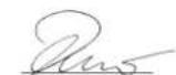
H. Jenner
Chairman of the Board of Management

S. Reiser
Director Regulatory Affairs & Certification
71364 Winnenden (Germany)
Tel.: +49 7195 14-0
Fax: +49 7195 14-2212
Spotrebný materiál
www.kaercher.com/REACH

Materijali ambalaže se mogu reciklirati. Ambala-žu odložite na otpad u skladu s propisima o očuvanju okoliša.

Električni i elektronički dijelovi često sadrže sastavne dijelove koji pri pogrešnom rukovanju ili pogrešnom zbrinjavanju mogu predstavljati potencijalnu opasnost za ljudsko zdravlje i okoliš. Ipak, ti sastavni dijelovi nužni su za propisani pogon uređaja. Uređaji označeni ovim simbolom ne smiju se odlagati u komunalni otpad. Stari uređaji sadrže vrijedne materijale koji se mogu reciklirati te bi ih stoga trebalo predati kao sekundarne sirovine. Primarne i punjive baterije sadrže tvari koje ne smiju dospjeti u okoliš. Stare uređaje kao i primarne odnosno punjive baterije odložite u otpad ekološki primjereno.
Jamstvo
text_image
Technical diagram of a mechanical or fluid system with labeled components and flow pathstext_image
Technical diagram of a mechanical valve assembly with numbered parts labeled 1 to 41 O-prsten, brtva na izlazu
2 Izlaz prema WPC 100 RO
3 Priključak zaporne slavine
text_image
Technical diagram of a mechanical assembly with numbered components for identification1 Vijčani spoj voda za otpadnu vodu (koncentrat)
2 Obujmica na izlazu otpadne vode (prednja strana)
3 Brtveni komad (samoljepiv)
4 Provrt (∅ 6 mm).
natural_image
Diagram of a mechanical device with a faucet and internal components, showing a close-up view of the shaft (no text or labels)Napomena
text_image
Technical diagram of a three-cylinder water treatment unit with labeled components1 Gornji filtar s aktivnim ugljenom 2 Membranski filtar (obrnuta osmoza) 3 Donja filtarska grupa (predfilter)
Priprema filtara za puštanje u rad
→ Tri čašice filtra donje filtarske grupe olabavite priloženim ključem (crni).
→ Odvrnite čašice filtra.
→ Izvadite filtarske uloške iz čašica filtra i uklonite zaštitnu foliju.
→ Navrnite čašicu filtra s filtarskim uloškom i pritegnite rukom.
natural_image
3D mechanical assembly diagram showing fluid flow paths with arrows indicating direction (no text or symbols)→ Skinite dovodna crijeva na membranskim filtrima i bočno ih provucite iz uređaja u prikladnu posudu.
natural_image
3D rendered mechanical components with curved brackets, no visible text or symbols→ Skinite gornji filtar s aktivnim ugljenom.
→ Kućišta membranskih filtara jedno za drugim izvadite iz držača.
→ Otpustite zaporni poklopac priloženim ključem (bijeli) i odvrnite ga.
→ Izvadite filtarske uloške (membranskih filtara) iz pakiranja i uklonite zaštitnu foliju.
→ Filtarske uloške postavite u kućišta filtara i utisnite ih tako da dosjednu do graničnika.
→ Navmite zaporni poklopac i ručno ga pritegnite.
→ Postavite kućište filtra u držač.
→ Dovodna crijeva još nemojte ponovno priključivati!
→ Ponovno postavite gornji filtar s aktivnim ugljenom.
→ Crijeva (plavo i crveno) za filtriranu vodu i koncentrat otpadne vode priključite na izlaze uređaja.
Ispiranje tri donja filtra (predfiltar)
natural_image
3D mechanical assembly diagram showing a robotic arm with a black arrow pointing to a component (no text or symbols present)natural_image
Mechanical assembly diagram showing two black arrows pointing to a cylindrical component mounted on a metal bracket (no text or symbols)→ Otvorite čičak trake.
natural_image
3D rendering of a mechanical assembly with cylindrical components and wiring (no visible text or symbols)natural_image
Illustration of a water purifier system with a hand holding a tool, accompanied by a separate inset showing a circular component (no text or symbols visible)→ Čašice filtra odvrnite priloženim crnim ključem.
natural_image
3D rendered mechanical assembly with cylindrical components and mounting brackets (no visible text or symbols)→ Skinite gornji filtar s aktivnim ugljenom.

natural_image
3D mechanical assembly diagram showing two cylindrical components and a base with curved blades (no text or symbols)→ Izvadite membranski filtar iz držača.
→ Zatvarač odvrnite priloženim bijelim ključem.
natural_image
Illustration of two mechanical components: a tool and a threaded component, with arrows indicating direction (no text or symbols)→ Uglavljeni membranski uložak oprezno odvojite alatom.
→ Membranski uložak rukom oprezno izvucite iz kučišta.
→ Umetnite novi membranski uložak.
→ Navrnite zatvarač.
Chairman of the Board of Management
S. Reiser
Director Regulatory Affairs & Certification
71364 Winnenden (Germany)
Tel.: +49 7195 14-0
Fax: +49 7195 14-2212
Potrošni materijal
| Oznaka Opis Kataloški br. | ||
| Fini filtar Prvi stupanj filtriranja za izdvajanje grubih čestica prljavštine 6.640-765.0 | ||
| Filtar s aktivnim ugljenom (granulat) | Drugi stupanj filtriranja za predodvajanje štetnih tvari | 6.640-766.0 |
| Filtar s aktivnim ugljenom (blok) | Treći stupanj filtriranja za fino odvajanje štetnih tvari | 6.640-767.0 |
| Membranski filtar (obrnuta osmoza) Četvrti stupanj filtriranja za desalinizaciju 6.640-783.0 | ||
| Gornji filtar s aktivnim ugljenom | Peti stupanj filtriranja za osiguranje neutralnog okusa nakon obrnute osmoze | 6.640-769.0 |
Intervali za zamjenu filtra
| Fini filtar 3 - 6 | Mjeseci ili po potrebi (vidi poglavlje: „Otklanjanje smetnji“) | |
| filtar s aktivnim ugljenom (granulat) 6 - 12 | ||
| filtar s aktivnim ugljenom (blok) 6 - 12 | ||
| membranski filtar (obrnuta osmoza) | 18 - 24 | |
| Filtar s aktivnim ugljenom | 6 - 12 |
Otklanjanje smetnji
| Smetnja | Moguć uzrok | Otklanjanje |
| Nema predaje vode | Utikač nije utaknut u utičnicu. | Utaknite strujni utikač. |
| Nema opskrbe vodom | Pobrinite se za dostatnu opskrbu vodom | |
| Tlačna sklopka na uređaju je neispravna | Kontaktirajte servis. | |
| Magnetni ventil je neispravan. | Kontaktirajte servis. | |
| Mala predaja vode | pumpa ne radi | Provjerite pumpu. |
| Bypas ventil je otvoren | Zatvorite Bypass ventil. | |
| Fini filtar je začepljen. | Zamijenite fini filtar. | |
| Membranski filtar (obrnuta osmoza) je začepljen. | Zamijenite membranski filtar (obrnuta osmoza). | |
| Pumpa se ne zaustavlja | Tlačna sklopka na izlazu uređaja je neispravna. | Kontaktirajte servis. |
| Pumpa se ne pokreće. | Tlačna sklopka na izlazu uređaja je neispravna. | Kontaktirajte servis. |
| Fini filtar je začepljen. | Zamijenite fini filtar. | |
| Tlačna sklopka na ulazi je neispravna. | Kontaktirajte servis. | |
| Nema opskrbe vodom | Provjerite dovod vode. | |
| Utikač nije utaknut u utičnicu. Utaknite strujni utikač. | ||
| Pumpa je neispravna. | Kontaktirajte servis. | |
| Istjecanje vode iz kućišta filtra | Kućište filtra nije pritegnuto. | Zategnite kućište filtra. |
| Brtveni prsten se pomakao ili je neispravan | Provjerite brtveni prsten, pravilno ga umetnite, a u slučaju oštećenja ga zamijenite. | |
| Voda izlazi samo na vodu za otpadnu vodu | Bypas ventil je otvoren. | Zatvorite Bypass ventil. |
| Membranski filtar (obrnuta osmoza) je začepljen. | Zamijenite membranski filtar (obrnuta osmoza). | |
| Pumpa je neispravna. | ||
| Upadljivi okus pitke vode | Gornji filtar s aktivnim ugljenom je istrošen. | Zamijenite gornji filtar s aktivnim ugljenom. |
| Pumpa se zaustavlja i nakon kratkog vremena se ponovno pokreće. | Propuštanje / gubitak vode / pad tlaka u uređaju ili u slijednom sustavu vodova. | Čvrsto pritegnite kućište filtra. |
| Polpuno zatvorite slavinu za vodu. | ||
| Pronađite i uklonite uzrok propuštanja. | ||
| Nepovratni ventil u uređaju je neispravan | Kontaktirajte servis. |
Tehnički podaci
| WPC 100 RO | ||
| Radni napon V/~/Hz 110...240/1/50-60 | ||
| Priključna snaga W80 | ||
| Najmanji strujni osigurač A6 | ||
| Tlak dovodne vode MPa (bar) 0,1...0,3 (1...3) | ||
| Temperatura vode na dotoku °C 5...45 | ||
| Snaga filtra l/h 70 | ||
| Učinak filtra (maks) l/h 100 | ||
| Okolna temperatura °C 5...45 | ||
| Širina mm 372 | ||
| Dubina | mm | 240 |
| Visina | mm | 530 |
| Težina (prazan) | kg | 13,45 |
| Težina uređaja spremnog za rad (napunjenog vodom s priborom) | kg | 17,86 |
| Razina zvučnog tlaka pri normalnom radu | dB(A) | < 60 |
| Materijali / Dozvole | Sve komponente koje provode pitku vodu su, prema opće priznatim pravilima tehnike, prikladne za primjenu u izravnom kontaktu s pitkom vodom. | |
Stupanj zadržavanja
www.kaercher.com/REACH
Ambalaža se može ponovo preraditi. Ambalažu odložite u otpad ekološki primereno.
Električni i elektronski uređaji sadrže često sastavne delove koji, u slučaju nepravilnog rukovanja ili nepravilnog odlaganja u otpad, mogu da predstavljaju potencijalnu opasnost za zdravlje ljudi i okolinu. Ipak, ovi sastavni delovi su neophodni za pravilan rad uređaja. Uređaji koji su označeni ovim simbolom ne smeju da se odlaju u kućni otpad.
Stari uređaji sadrže vredne materijale sa sposobnošću recikliranja i treba ih dostaviti na ponovnu preradu. Primarne i punjive baterije sadrže materije koje ne smeju dospeti u životnu sredinu. Stare uređaje kao i baterije ili akumulatore odložite u otpad ekološki primereno
Garancija
U svakoj zemlji važe garantni uslovi koje je izdala naša nadležna distributivna organizacija. Eventualne smetnje na uredaju za vreme trajanja garancije uklanjamo besplatno, ukoliko je uzrok greška u materijalu ili proizvodnji. U slučaju koji podleže garanciji obratite se sa potvrdom o kupovini Vašem prodavcu ili najbližoj ovlašćenoj servisnoj službi.
Rezervni delovi
text_image
Technical diagram of a mechanical or fluid system with labeled components and flow paths1 T-element cevovoda
2 Vod za otpadnu vodu (koncentrat)
text_image
Technical diagram of a mechanical valve assembly with numbered parts labeled 1 to 41 O-prsten, zaptivka na izlazu
2 Izlaz prema WPC 100 RO
3 Priključak slavine za zatvaranje
text_image
Technical diagram of a mechanical assembly with numbered components for identification1 Zavrtni spoj voda za otpadnu vodu (koncentrat)
2 Obujmica cevi na izlazu otpadne vode (prednja strana)
3 Zaptivni komad (samolepljivi)
4 Otvor (∅ 6 mm).
natural_image
Technical diagram of a mechanical device with a lever and internal components, showing no text or symbols.Napomena
Slavina sveže vode treba da se montira preko korita sa priključkom prema kanalu otpadne vode.
→ Slavinu sveže vode montirati kao što je prikazano.
→ Prečnik otvora: 12 mm
→ Prilikom montaže voditi računa o pravilnom rasporedu pojedinačnih delova.
→ Crevni vod priključiti na izlaz za svežu vodu na uređaju.
→ Crevni vod priključiti na slavinu sveže vode. Alternativno, slavina sveže vode može da se pričvrsti direktno na zid pomoću priloženog montažnog ugaonika.
Stavljanje u pogon
Prvo puštanje u rad
Pre prvog ispuštanja vode za piće, sistem mora da se napuni i ispere.
⚠️UPOZORENJE
text_image
Technical diagram of a three-cylinder water treatment unit with labeled components1 Gornji filter sa aktivnim ugljem
2 Membranski filter (obrnuta osmoza)
3 Donja filterska grupa (predfilter)
natural_image
3D mechanical assembly diagram showing fluid flow paths with arrows indicating direction (no text or symbols)→ Skinuta dovodna creva na membranskim filterima i izvesti ih bočno iz uređaja u odgovarajuću posudu.

natural_image
3D rendered mechanical components with two cylindrical parts and curved brackets, no visible text or symbolsnatural_image
3D mechanical assembly diagram showing internal components and directional arrows (no text or symbols)→ Otvoriti premosni ventil.
→ Priključiti creva (crveno i plavo).
→ Otvoriti slavinu sveže vode.
natural_image
Mechanical assembly diagram showing two black arrows pointing to a cylindrical component mounted on a metal frame (no text or symbols)→ Otvorite čičak-trake.
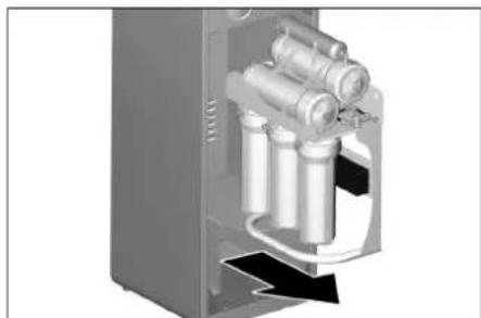
natural_image
3D rendering of a mechanical device with cylindrical components and wiring (no visible text or symbols)→ Izvaditi filtersku jedinicu i odložiti ispred uređaja.
→ Informacije o zameni filtera pronadite u poglavlju „Nega i održavanje / zamena filterskih umetaka“
→ Nakon zamene filtera, uređaj ponovo ugradite po obrnutom redosledu.
Uzimanje vode iz uređaja Kärcher WPD
Rukovanje WPD vodomatom je opisano u uputstvu za rad uređaja.
Nega i održavanje
Napomene za održavanje
⚠UPOZORENJE
Opasnost po zdravlje usled nestručno obavljene popravke uređaja. Uređaj sme popravljati samo obučeno stručno osoblje.
natural_image
Illustration of a water purifier system with a hand adjusting its components (no text or symbols visible)natural_image
3D rendered mechanical assembly with cylindrical components and mounting brackets (no visible text or symbols)natural_image
3D mechanical assembly diagram showing two cylindrical components and a fan-like structure (no text or symbols)natural_image
Illustration of a tool interacting with a threaded component, showing directional arrows (no text or symbols)
Chairman of the Board of Management
S. Reiser
Director Regulatory Affairs & Certification
Opunomoćeni za izradu dokumentacije: S. Reiser
Alfred Kärcher SE & Co. KG
71364 Winnenden (Germany)
Tel.: +49 7195 14-0
Fax: +49 7195 14-2212
Potrošni materijal
| Oznaka Opis Kataloški br. | ||
| Fini filter Prva faza filtriranja za zadržavanje grubih čestica prljavštine 6.640-765.0 | ||
| Filter sa aktivnim ugljem (granulati) | Druga faza filtriranja za predodvajanje štetnih materija | 6.640-766.0 |
| Filter sa aktivnim ugljem (blok) | Treća faza filtriranja za fino odvajanje štetnih materija | 6.640-767.0 |
| Membranski filter (obrnuta osmoza) Četvrta faza filtriranja za desalinizaciju 6.640-783.0 | ||
| Gornji filter sa aktivnim ugljem Peta faza filtriranja za obezbeđenje neutralnog ukusa nakon obrnute osmoze 6.640-769.0 | ||
Intervali zamene filtera
www.kaercher.com/REACH
text_image
Technical diagram of a mechanical or fluid system with labeled components and directional arrows indicating flow or movement.text_image
Technical diagram of a mechanical assembly with numbered components for identificationnatural_image
Technical diagram of a mechanical device with a lever and internal components, showing no text or symbols.Указание
text_image
Technical diagram of a three-tiered cylindrical water treatment device with labeled componentsnatural_image
3D mechanical assembly diagram showing fluid flow paths with arrows indicating direction (no text or symbols)natural_image
3D rendered mechanical components with cylindrical and curved arms (no text or symbols visible)natural_image
3D rendered mechanical assembly with arrows indicating motion or force direction (no text or symbols)natural_image
Mechanical assembly diagram showing two black arrows pointing to a cylindrical component mounted on a metal bracket (no text or symbols)natural_image
3D cutaway view of a mechanical device showing internal components (no text or symbols visible)natural_image
Illustration of a water treatment device with cylindrical tanks and a hand holding a valve (no text or symbols visible)natural_image
3D rendered mechanical assembly with cylindrical components and mounting brackets (no visible text or symbols)natural_image
3D mechanical assembly diagram showing two cylindrical components and a base with curved blades (no text or symbols)natural_image
Illustration of two mechanical components: a tool and a threaded pipe, with arrows indicating direction (no text or symbols)
Chairman of the Board of Management
Director Regulatory Affairs & Certification
71364 Winnenden (Germany)
Tel.: +49 7195 14-0
Fax: +49 7195 14-2212
Консумативи
text_image
Technical diagram of a mechanical or fluid system with labeled components and flow paths1 Toorveetoru T-detail
2 Heitveetoru (kontsentraat)
text_image
Technical diagram of a mechanical valve assembly with numbered parts labeled 1 to 4text_image
Technical diagram of a mechanical assembly with numbered components for identificationnatural_image
Diagram of a mechanical device with a faucet and internal components, showing a close-up view of the shaft (no text or labels)Märkus
text_image
Technical diagram of a three-cylinder water treatment unit with labeled componentsnatural_image
3D mechanical assembly diagram showing fluid flow paths with arrows indicating direction (no text or symbols)natural_image
3D rendered mechanical components with cylindrical and curved arms (no text or symbols)natural_image
3D mechanical assembly diagram showing internal components with arrows indicating motion or force (no text or symbols)natural_image
Mechanical assembly diagram showing two black arrows pointing to a cylindrical component mounted on a metal bracket (no text or symbols)→ Avage takjapael.
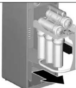
natural_image
3D rendering of a mechanical assembly with cylindrical components and housing (no visible text or symbols)natural_image
Technical illustration of a water treatment device with cylindrical tanks and a hand holding a valve (no text or symbols visible)natural_image
3D rendered mechanical assembly with cylindrical components and mounting brackets (no text or symbols visible)natural_image
3D rendering of two cylindrical devices emitting a fan-like structure, possibly a mechanical or electronic component (no text or symbols visible)natural_image
Illustration of a tool applying force to a threaded component, showing mechanical assembly (no text or symbols)Toode: reoveepuhasti
Tüüp: 1.024-xxx
H. Jenner
Chairman of the Board of Management
S. Reiser
Director Regulatory Affairs & Certification
71364 Winnenden (Germany)
Tel.: +49 7195 14-0
Fax: +49 7195 14-2212
Kulumaterjal
www.kaercher.com/REACH
text_image
Technical diagram of a mechanical or fluid system with labeled components and directional arrows indicating flow or movement.text_image
Technical diagram of a mechanical valve assembly with numbered parts labeled 1 to 4text_image
Technical diagram of a mechanical clamp assembly with numbered parts labeled 1 through 6natural_image
Diagram of a mechanical device with a lever and internal components, showing a close-up view of the lever assembly (no text or labels)Norādījums
text_image
Technical diagram of a three-cylinder water treatment unit with labeled componentsnatural_image
Mechanical assembly diagram showing three cylindrical components with black arrows indicating directional movement (no text or symbols)natural_image
3D rendered mechanical components with curved brackets, no visible text or symbolsnatural_image
3D mechanical assembly diagram with arrows indicating motion or force direction (no text or symbols)natural_image
Mechanical assembly diagram showing two black arrows pointing to a pipe connection (no text or symbols present)natural_image
3D mechanical assembly diagram showing internal components with no visible text or symbolsnatural_image
Illustration of a water purifier system with a hand holding a tool, accompanied by a separate inset showing a circular component (no text or symbols visible)natural_image
3D rendered mechanical assembly with cylindrical components and mounting brackets (no text or symbols visible)natural_image
3D mechanical assembly diagram showing two cylindrical components and a fan-like structure with curved blades (no text or symbols)natural_image
Illustration of two mechanical components: a tool and a threaded component, both with directional arrows indicating movement (no text or symbols)
H. Jenner
Chairman of the Board of Management

S. Reiser
Director Regulatory Affairs & Certification
71364 Winnenden (Germany)
Tel.: +49 7195 14-0
Fax: +49 7195 14-2212
Izmantotie materiāli
www.kaercher.com/REACH
text_image
Technical diagram of a mechanical or fluid system with labeled components and flow pathstext_image
Technical diagram of a mechanical valve assembly with numbered parts labeled 1 to 4text_image
Technical diagram of a mechanical assembly with numbered components for identificationnatural_image
Technical diagram of a mechanical device with a lever and internal components, showing no text or symbols.Pastaba
text_image
Technical diagram of an internal water treatment device with labeled components 1, 2, and 3natural_image
Mechanical assembly diagram showing three cylindrical tanks with black arrows indicating flow direction (no text or symbols)natural_image
3D rendered mechanical components with cylindrical bodies and support brackets (no text or symbols)natural_image
3D mechanical assembly diagram showing internal components and directional arrows (no text or symbols)natural_image
Mechanical assembly diagram showing two black arrows pointing to a cylindrical component mounted on a metal frame (no text or symbols)natural_image
3D diagram of a mechanical device with cylindrical components and an arrow indicating direction (no text or symbols)natural_image
Illustration of a water purifier system with a hand holding a tool, accompanied by a separate inset showing a circular component (no text or symbols visible)natural_image
3D rendered mechanical assembly with cylindrical components and mounting brackets (no text or symbols visible)natural_image
3D mechanical assembly diagram showing two cylindrical components and a base with curved blades (no text or symbols)natural_image
Illustration of a hand using a tool to adjust a threaded component, with arrows indicating direction (no text or symbols)
H. Jenner
Chairman of the Board of Management
S. Reiser
Director Regulatory Affairs & Certification
71364 Winnenden (Germany)
Tel.: +49 7195 14-0
Fax: +49 7195 14-2212
Nusidėvinčios dalys
www.kaercher.com/REACH
text_image
B C → → ✓А Кріплення шлангу
text_image
Technical diagram of a mechanical or fluid system with labeled components and flow pathstext_image
Technical diagram of a mechanical valve assembly with numbered parts labeled 1 to 4text_image
Technical diagram of a mechanical assembly with numbered components for identificationnatural_image
Technical diagram of a mechanical device with a lever and internal components, showing no text or symbols.Вказівка
text_image
Technical diagram of a three-cylinder water treatment unit with labeled componentsnatural_image
3D mechanical assembly diagram showing pipe connections and structural components (no text or symbols)natural_image
3D rendered mechanical components with cylindrical and curved arms (no text or symbols)natural_image
3D mechanical assembly diagram showing internal components and directional arrows (no text or symbols)natural_image
Mechanical assembly diagram showing two black arrows pointing to a cylindrical component mounted on a metal frame (no text or symbols)natural_image
3D rendering of a mechanical device with cylindrical components and internal tubing (no visible text or symbols)natural_image
Illustration of a water treatment device with three cylindrical tanks and a hand adjusting a valve (no text or symbols visible)natural_image
3D rendered mechanical assembly with cylindrical components and mounting brackets (no visible text or symbols)natural_image
3D mechanical assembly diagram showing two cylindrical components and a fan-like structure with no visible text or symbolsnatural_image
Illustration of two mechanical components: a tool and a threaded component, with arrows indicating direction (no text or symbols)
H. Jenner
Chairman of the Board of Management
S. Reiser
Director Regulatory Affairs & Certification
71364 Winnenden (Germany)
Tel.: +49 7195 14-0
Fax: +49 7195 14-2212
Видатковий материал
www.kaercher.com/REACH

text_image
B C → → ✓A 固定软管
B 松开软管
→ 在插入前截短软管。
提示
截短软管,切口不得歪斜。斜切的软管将导致不密封!
连接设备
提示
text_image
Technical diagram of a mechanical or fluid system with labeled components and flow pathstext_image
Technical diagram of a valve assembly with numbered parts labeled 1 to 4text_image
Technical diagram of a mechanical assembly with numbered components for identificationnatural_image
Technical diagram of a mechanical device with a circular inset showing internal components (no text or labels)提示
text_image
Technical diagram of a three-cylinder engine with labeled components 1, 2, and 3natural_image
3D mechanical assembly diagram showing fluid flow paths with arrows indicating direction (no text or symbols)natural_image
3D rendered mechanical components with cylindrical and curved arms (no text or symbols)natural_image
3D mechanical assembly diagram showing a robotic arm with directional arrows and components (no text or labels)natural_image
Mechanical assembly diagram showing two black arrows pointing to a cylindrical component mounted on a metal bracket (no text or symbols)→ 打开粘扣带。
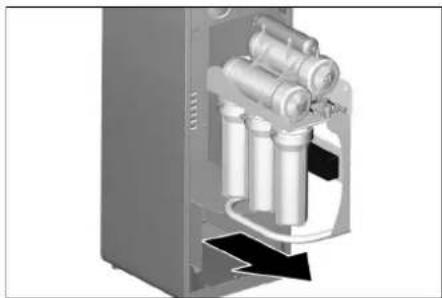
natural_image
3D mechanical assembly diagram showing internal components with no visible text or symbolsnatural_image
Illustration of a water treatment device with a hand adjusting its internal components (no text or symbols visible)natural_image
3D rendered mechanical assembly with cylindrical components and mounting brackets (no visible text or symbols)→ 取下上面的活性炭过滤器。
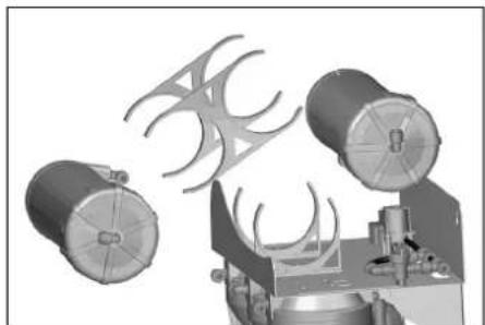
natural_image
3D rendering of two cylindrical devices emitting a fan-like structure, possibly a mechanical or industrial component (no text or symbols visible)natural_image
Illustration of two mechanical components: a tool and a threaded pipe, with arrows indicating direction (no text or symbols)www.kaercher.com/REACH
text_image
Technical diagram of a valve assembly with numbered parts labeled 1 to 4text_image
Technical diagram of a mechanical clamp assembly with numbered parts labeled 1 through 6natural_image
Diagram of a mechanical device with a lever and internal components, showing a close-up view of the component (no text or labels)text_image
Technical diagram of a mechanical or fluid system with labeled components and flow pathstext_image
Technical diagram of a three-cylinder water treatment unit with labeled componentsnatural_image
Mechanical assembly diagram showing fluid flow paths with arrows indicating movement (no text or symbols)natural_image
3D rendered mechanical components with cylindrical and curved arms (no text or symbols)natural_image
3D mechanical assembly diagram showing interconnected components with arrows indicating motion (no text or symbols)natural_image
Mechanical assembly diagram showing two black arrows pointing to a cylindrical component mounted on a metal bracket (no text or symbols)→ فتح شریط فيلكرو