HL 850 EBPlus - Plane FESTOOL - Free user manual and instructions
Find the device manual for free HL 850 EBPlus FESTOOL in PDF.
| Product type | Planer |
| Brand | Festool |
| Model | HL 850 EBPlus |
| Power | 850 W |
| Idle speed | 12,000 rpm |
| Planing width | 82 mm |
| Depth of cut | 0 – 3.5 mm |
| Max. rabbet depth | Unlimited |
| Weight | 3.9 kg |
| Power supply | 220–240 V / 120 V depending on region, 50/60 Hz |
| Protection class | II |
| Sound pressure level | 87 dB(A) |
| Sound power level | 95 dB(A) |
| Vibration emission value | < 2.5 m/s² |
| Soft start | Yes |
| Brake (EB model) | Yes, stop in 1.5 to 2 seconds |
| Constant speed | Yes, electronic regulation |
| Chip ejection | Adjustable left/right |
| Dust extraction connection | Ø 36 mm |
| Included cutter head | HK 82 SD (helical blades) |
| Machinable materials | Wood, soft plastics, similar materials |
| Compatible accessories | Depth stop, parallel guide, angle stop, rusticated cutter heads |
| Maintenance | Automatic cut-off brushes, cleaning ventilation slots |
| Intended use | Professional use on non-metallic materials |
Frequently Asked Questions - HL 850 EBPlus FESTOOL
User questions about HL 850 EBPlus FESTOOL
0 question about this device. Answer the ones you know or ask your own.
Ask a new question about this device
Download the instructions for your Plane in PDF format for free! Find your manual HL 850 EBPlus - FESTOOL and take your electronic device back in hand. On this page are published all the documents necessary for the use of your device. HL 850 EBPlus by FESTOOL.
USER MANUAL HL 850 EBPlus FESTOOL
en: EU Declaration of Conformity. We declare under sole responsibility that this product complies with all the relevant requirements in the following EU Directives, and following standards or normative documents were applied:
We as the manufacturer declare under our sole responsibility that the product(s) fulfill(s) all the relevant provisions of the following UK Regulations and are manufactured in accordance with the following designated standards:
S.l. 2008/1597
Supply of Machinery [Safety] Regulations 2008
S.l. 2016/1091
Electromagnetic Compatibility Regulations 2016
S.I. 2021/422
Restriction of the Use of Certain Hazardous Substances in Electrical and Electronic Equipment Regulations 2012
BS EN 62841-1:2015 + AC:2015 + A11:2022
BS EN 62841-2-14: 2015,
BS EN 55014-1:2017 + A11:2020,
BS EN 55014-2:1997 + A1:2001 + A2:2008 + AC:1997,
BS EN 61000-3-2:2014,
BS EN 61000-3-3:2013
BS EN IEC 63000:2018
Head of Research & Development Products

Tim Weber
Head of Product Compliance
Inhaltsverzeichnis
1 Symbols. 14
2 Safety warnings. 14
3 Intended use. 15
4 Technical data. 15
5 Parts of the device. 15
6 Commissioning. 15
7 Settings. 15
8 Working with the electric power tool. 17
9 Accessories. 18
10 Service and maintenance. 18
11 Environment. 18
12 General information. 19
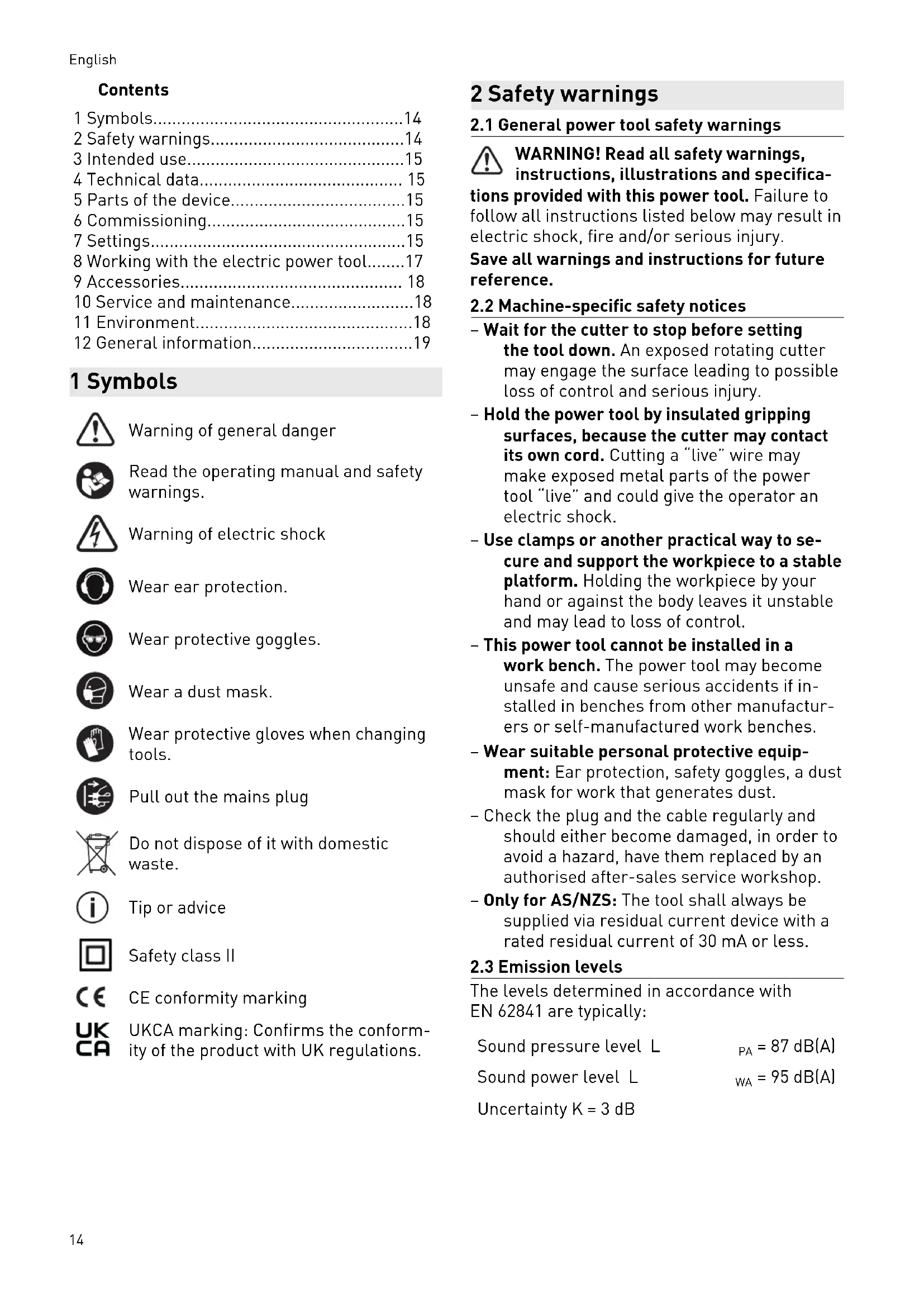
1 Symbols

Warning of general danger

Read the operating manual and safety warnings.

Warning of electric shock

Wear ear protection.

Wear protective goggles.

Wear a dust mask.

Wear protective gloves when changing tools.

Pull out the mains plug.

Do not dispose of it with domestic waste.

Tip or advice

Safety class II

CE conformity marking

UKCA marking: Confirms the conformity of the product with UK regulations.
2 Safety warnings
2.1 General power tool safety warnings

WARNING! Read all safety warnings, instructions, illustrations and specifica
tions provided with this power tool. Failure to follow all instructions listed below may result in electric shock, fire and/or serious injury.
Save all warnings and instructions for future reference.
2.2 Machine-specific safety notices
- Wait for the cutter to stop before setting the tool down. An exposed rotating cutter may engage the surface leading to possible loss of control and serious injury.
- Hold the power tool by insulated gripping surfaces, because the cutter may contact its own cord. Cutting a "live" wire may make exposed metal parts of the power tool "live" and could give the operator an electric shock.
- Use clamps or another practical way to secure and support the workpiece to a stable platform. Holding the workpiece by your hand or against the body leaves it unstable and may lead to loss of control.
- This power tool cannot be installed in a work bench. The power tool may become unsafe and cause serious accidents if installed in benches from other manufacturers or self-manufactured work benches.
- Wear suitable personal protective equipment: Ear protection, safety goggles, a dust mask for work that generates dust.
- Check the plug and the cable regularly and should either become damaged, in order to avoid a hazard, have them replaced by an authorised after-sales service workshop.
- Only for AS/NZS: The tool shall always be supplied via residual current device with a rated residual current of 30mA or less.
2.3 Emission levels
The levels determined in accordance with EN 62841 are typically:
Sound pressure level L PA = 87dB(A)
Sound power level L WA = 95 dB(A)
Uncertainty K = 3 dB

CAUTION
Noise emissions created while working with the power tool may damage your hearing.
Always use ear protection.
Vibration emission level a_h (vector sum for three directions) and uncertainty K measured in accordance with EN 62841:
$$ a _ {h} < 2. 5 \mathrm {m} / \mathrm {s} ^ {2} $$
$$ K = 1. 5 \mathrm {m} / \mathrm {s} ^ {2} $$
The specified emission levels (vibration, noise)
- are used to compare machines.
- They are also used for making preliminary estimates regarding vibration and noise load during operation.
- They represent the primary applications of the power tool.

CAUTION
The emission values may deviate from the specified values. This is dependent on how the tool is used and the type of workpiece being machined.
Assess the actual load during the entire operating cycle.
Depending on the actual load, suitable protective measures must be defined in order to protect the operator.
3 Intended use
The planer is suitable for machining
-
soft plastics, wood and similar materials,
-
using only Festool insertion tools.
Only use planing heads that are designed for a maximum speed of 15,000 rpm.

The user is liable for improper or non-intended use.
4 Technical data
Planer HL 850 E, HL 850 EB
Power 850 W
Speed (no-load) 12,000 rpm
Planing width 82 mm
Chip depth 0-3.5 mm
Max. rebate depth Unlimited
Weight 3.9kg
5 Parts of the device
[1-1] Lever for guard
[1-2] Hexagon wrench
[1-3] Handle/chip thickness setting
[1-4] Lock for chip thickness setting
[1-5] Operating lever for chip ejector
[1-6] Chip ejector
[1-7] On/off switch
[1-8] Safety lock
[1-9] Handle
[1-10] Support
[1-11] Spindle lock
The specified illustrations appear at the beginning of the Operating Instructions.
6 Commissioning

WARNING
Unauthorised voltage or frequency.
Risk of accidents
The mains voltage and the frequency of the power source must correspond to the specifications on the name plate.
In North America, only Festool machines with the voltage specifications 120V / 60Hz may be used.

WARNING
Risk of injury
Always switch off the machine before connecting and disconnecting the mains power cable.
To switch the device on, first push down on the safety lock [1-8] and then press the switch [1-7].
To switch on: Press [1-7]
To switch off: Release [1-7]
7 Settings

WARNING
Risk of injury, electric shock
Always disconnect the mains plug from the socket before performing any work on the machine.
7.1 Electronics
The power tool features full-wave electronics with the following properties:
Smooth start-up
The electronically controlled smooth start-up function ensures that the power tool starts up smoothly.
Constant speed
The motor speed is electronically kept constant. This ensures a uniform cutting speed even when under load.
Brake (HL 850 EB)
The tool is electronically braked to a stop within 1.5 to 2 seconds of being switched off.
7.2 Setting the chip thickness
- Open the lock [3-1] by pushing it backwards.
Set the required chip thickness by turning the handle [3-2]. The scale [3-3] displays the set chip thickness. - Close the lock by pushing it forwards to prevent the set chip thickness being changed.
The maximum chip removal is 3.5mm . To prevent overloading of the power tool, we recommend that you do not feed more than 2.5mm with a planing width of >40mm . If you continue turning the handle beyond the 0 marking, you will reach position P = park position. In position P, the blade of the planing head is fully retracted behind the planer foot. Note: This does not apply to the rustic planing heads.
7.3 Changing the planing head

CAUTION
Risk of injury from hot and sharp tool.
- Do not use any blunt or faulty tools.
Wear protective gloves when handling a tool.
Press and hold the spindle lock [1-11].
- Use a hexagon wrench [2-7] to undo the screw [2-2].
Pull the planing head [2-6] off the shaft.
Clean the shaft to remove any deposits.
Place a new planing head on the shaft.
- Secure the new planing head with the clamping flange [2-4], the washer [2-3] and the screw [2-2]. Tighten the screw.
7.4 Changing the spiral blade

WARNING
Risk of kickback and poor quality of planing work from worn spiral blade
- Only use sharp and undamaged spiral blades.


CAUTION
Risk of injury from hot and sharp tool.
- Do not use any blunt or faulty tools.
Wear protective gloves when handling a tool.
The planer comes with the HK 82 SD planing head as standard. The planing head has cutting edges inserted at an angle, which means that the planer blades cannot be reground.
Use a hexagon wrench [1-2] to undo the three screws [4-1] in the planing head.
Pull the spiral blade [4-2] out from the side of the planing head.
Clean the retaining groove for the spiral blade. Note: To prevent corrosion on the planing head, the cleaning agent used must have a pH between 4.5 and 8.
- Push a new spiral blade into the retaining groove of the planing head so that the labelled side faces the rear planer foot.
Using a ruler [4-3], align the spiral blade so that the front side is flush with the front and rear planer feet of the planer.
A spiral blade that protrudes outwards or is set back inwards on the front side distorts the rebate width.
- Tighten the middle screw first, followed by the two outer screws [4-1].
7.5 Installing stops (included in accessories in some cases)
Installing the FA-HL rebate depth stop
- Secure the rebate depth stop [2-1] in the threaded hole [2-14] on the right-hand side of the device.
The rebate depth stop can be adjusted anywhere between 0 and 30mm according to the scale. The set rebate depth is read from the marking on the ribbing [2-13].
Installing the PA-HL parallel side fence
- Secure the parallel side fence [2-11] in the threaded hole [2-14] on the left-hand side of the device.
To plane along an edge, first loosen the clamp [2-10], then use the fence to adjust the planing width between 0 and 82mm .
Installing the WA-HL angle stop
- Secure the angle stop in the threaded hole [2-14] in the same way as the parallel side fence.
7.6 Dust extraction


WARNING
Health hazard posed by dust
Always work with an extractor.
Comply with national regulations.
Wear a dust mask.
Chips can be ejected either out of the right [5-3] or left [5-4] opening using the toggle lever [5-2]. Either a chip collection bag or an extractor hose (dia. 36mm ) can be connected to both openings.
CAUTION! Always use an antistatic suction hose (AS). A slight electric shock may cause you to panic briefly and become distracted, which may result in an accident.
SB-HL chip collection bag (accessory)
The chip collection bag is attached using the AD-HL adapter [5-6].
- Use the tab [5-5] to mount the adapter on the bottom edge of the chip ejector opening and turn the rotary knob [5-7] to fasten it in the threaded hole [5-1].
Extractor hose
An extractor hose (dia. 36mm ) can either be inserted directly into the chip ejector opening or into the AD-HL adapter for the chip collection bag.
8 Working with the electric power tool

WARNING
Risk of injury, damage to the spiral blade
- Remove metals from the surface to be planed.

WARNING
Risk of injury
- Secure the workpiece in such a way that it cannot move during machining.
When working, hold the power tool with both hands on the intended handles [1-3], [1-9].
Set the required chip thickness.
- Place the planer with the front planer foot on the workpiece without touching the workpiece with the planing head.
Switch on the planer.
Guide the planer over the workpiece so that the planer foot is lying flat on the workpiece.
Apply pressure to the front planer foot when starting to plane.
Apply pressure to the rear planer foot for the remainder of the planing process.
8.1 Placing the power tool down

WARNING
Risk of injury
- Use the power tool only with fully functional support foot [2-8].
The planing shaft continues to run for a few seconds after it has been switched off. Wait until the planing shaft comes to a standstill.
The power tool has a support foot [2-8] at the end of the planer foot to safely place the planer down.
When the power tool is lifted up, the support foot automatically extends over the planer foot so that the planing shaft does not touch the surface when the planer is placed down on a flat surface.
If the support foot should be prevented from protruding beyond the planer foot in specific applications, it can be locked in the upper position by pushing on it from the side [2-8].
8.2 Rebating
The planer can be used to plane a rebate of unlimited depth.
- Move the guard [7-1] away by first pushing the lever [7-2] forwards and then to the left.
The front side of the planing head is now exposed.
Once work is complete, the guard automatically returns to position through spring action.
8.3 Chamfering
To chamfer workpiece edges, the front planer foot has a 90^ V-shaped groove [2-12]. This V-shaped groove is 2 mm deep, so that when the chip thickness is set to 0, the edge is broken by 2 mm.
8.4 Rustic planing heads (accessories)
You can use the planer to produce rustic-look surfaces. Three rustic planing heads are available for this:
HK 82 RG: Produces a surface with a coarse surface finish.
- HK 82 RF: Produces a surface with a fine surface finish.
HK 82 RW: Produces a surface with irregular undulations.
NOTICE The blades on the rustic planing heads (HK 82 RF, HK 82 RG, HK 82 RW) protrude from the planer foot by approx. 1.6mm . This means that the cutting depth must be set to 0mm when using the rustic planing heads on the planer. Otherwise there is a risk that the blades on the rustic planing heads will route into the planer foot and destroy the planer.
The cutting depth limiter [6-2] prevents the cutting depth from being accidentally increased when working with the planer. Always attach the cutting depth limiter to the planer before working with a rustic planing head:
- Set the cutting depth on the planer to 0 mm .
- Use the rotary knob [6-1] to secure the cutting depth limiter in the threaded hole [6-3].
9 Accessories
Always use original Festool tools and original Festool accessories. Using low-quality tools or accessories from other manufacturers may increase the risk of injury and seriously unbalance the machine, decreasing the quality of the working results and accelerating power tool wear.
You can find the PO numbers for accessories and tools under www.festool.co.uk.
10 Service and maintenance

WARNING
Risk of injury, electric shock
Always pull the mains plug from the socket before performing any servicing and maintenance work.
- All maintenance and repair work which requires the motor housing to be opened should always be carried out by an authorised service workshop.
Customer service and repairs must only be carried out by the manufacturer or service workshops. You must only use original Festool spare parts.
Further information: www.festool.co.uk/service To ensure constant air circulation, always keep the cooling air openings in the motor housing clean and free of blockages.
The tool is equipped with special self-disconnecting carbon brushes. If they wear out, the power supply is disconnected automatically and the tool stops.
To clean the chip ejector:
- Remove the adapter [5-6] (if applicable).
- Empty the adapter, remove any blockages.
- Release any chips jammed in the ejector opening [5-4], if necessary clean the power tool with a resin-based solvent.
In the case of extreme contamination, remove the planing head (see section 7.3) and clean the chip ejector opening.
Connect the dust extractor (see section 7.6) and extract dust from the chip ejector opening.
11 Environment

Do not dispose of the device in the household waste! Recycle devices, accessories and packaging. Observe appli-national regulations.
In accordance with the European Directive on waste electrical and electronic equipment and implementation in national law, used electrical devices must be collected separately and handled in for environmentally friendly recycling. Information on the collection points can be viewed at www.festool.com/environment.
Information on critical materials:
www.festool.co.uk/reach
12 General information
Imported into the UK by
Festool UK Ltd
1 Anglo Saxon Way
Bury St Edmunds
IP30 9XH
Great Britain
Sommaire
Varning for allman risk