BME 18.0EC - Polisher Flex - Free user manual and instructions
Find the device manual for free BME 18.0EC Flex in PDF.

| Product type | Cordless polisher (battery-powered) |
| Brand | Flex |
| Model | BME 18.0EC |
| Rated voltage | 18 V |
| Battery type | Li-ion (2.5 Ah or 5.0 Ah) |
| No-load speed (polishing) | 2125 / 2990 / 3850 / 4700 min⁻¹ (4 positions) |
| Max tool diameter | 125 mm (with BS 50 adapter) |
| Weight (without battery) | 2.3 kg |
| Weight with battery (2.5 Ah / 5.0 Ah) | 2.72 kg / 3.02 kg (approx.) |
| Sound pressure level (LpA) | 79 dB(A) |
| Vibration emission value (polishing) | 3.5 m/s² (uncertainty K=1.5 m/s²) |
| Power supply | Interchangeable battery (AP 18.0 system) |
| Main functions | Polishing, satin finishing, structuring, brushing, smoothing, rust removal, deburring (metals) |
| Compatible adapters | LK 152 (weld grinding), BS 50 (polishing), BR 50 (tube belt sanding), BF 140 (belt sanding) |
| Safety | Overload protection, temperature monitoring, automatic brush stop |
| Maintenance | Regular cleaning of ventilation slots and dust filter; replacement of carbon brushes |
| Spare parts and repairability | Abrasive discs, backer pads, belts, carbon brushes, rollers, sanding arms; repair by authorized service center |
| Use | Professional (industry and trade) |
| Materials processed | Steel, stainless steel, non-ferrous metals (wood not permitted) |
Frequently Asked Questions - BME 18.0EC Flex
User questions about BME 18.0EC Flex
0 question about this device. Answer the ones you know or ask your own.
Ask a new question about this device
Download the instructions for your Polisher in PDF format for free! Find your manual BME 18.0EC - Flex and take your electronic device back in hand. On this page are published all the documents necessary for the use of your device. BME 18.0EC by Flex.
USER MANUAL BME 18.0EC Flex
natural_image
Illustration of various types of mechanical tools including a power tool, saw, and clamp (no text or symbols present)de Originalbetriebsanleitung 3
en Original operating instructions 23
fr Notice d'instructions d'origine 42
it Istruzioni per l'uso originali 62
es Instrucciones de funcionamiento originales ..... 82
pt Instruções de serviço originais .....102
nl Originele gebruiksaanwijzing .....122
da Originale driftsvejledning .....142
no Originale driftsanvisningen .....160
sv Originalbruksanvisning ....178
fi Alkuperäinen käyttöohjekirja ....196
el Auθεντικές οδηγίες χειρισμού .....215
tr Orijinal işletme kılavuzu 237
pl Instrukcja oryginalna .....257
hu Eredeti üzemeltetési útmutató .....278
cs Originální návod k obsluze .....298
sk Originálny návod na obsluhu .....317
hr Originalna uputa za rad 338
sl Izvirno navodilo za obratovanje 356
ro Instructiuni de functionare originale 374
bg Оригинално упътване за експлоатация ..... 394
ru Оригинальная инструкция по эксплуатации .....417
et Originaalkasutusjuhend 440
It Originali naudojimo instrukcija ....458
Iv Lietošanas pamācības oriģināls .....477
ar 513 ترجمة لإرشادات الأنشغير الأصلية
Inhalt
Verwendete Symbole 3
Symbole am Gerät 3
natural_image
Illustration of a hand using a tool to cut a tire on a textured surface, with directional arrows indicating motion (no text or symbols)natural_image
Illustration of a robotic hand gripping a metal rod, no text or symbols presentnatural_image
Mechanical assembly diagram showing a clamping mechanism with no visible text or symbolsRollen wechseln
Antriebsrolle:
natural_image
Technical illustration of a mechanical tool with a magnified inset showing a disassembled part (no text or symbols present)Bandlauf einstellen
natural_image
Illustration of a hand using a tool to adjust or install a mechanical component, with no visible text or symbols.natural_image
Illustration of a hand using a manual tool to adjust or install a mechanical component (no text or symbols visible)natural_image
Close-up of a mechanical component with an arrow indicating direction, no visible text or symbolsnatural_image
Close-up of a mechanical component with a black arrow pointing to a button (no visible text or symbols)natural_image
Close-up of a microwave oven with a black arrow pointing to the button (no visible text or symbols)natural_image
Two-panel illustration showing a car's front and side views of a mesh grille (no text or symbols)Symbols used in this manual ..... 23
Symbols on the device 23
Important safety information ..... 23
Noise and vibration 29
Technical data 30
Overview 31
Instructions for use 32
Maintenance and care 39
Disposal information 40
C ∈ Declaration of Conformity ..... 40
UK CO Declaration of Conformity ..... 41
Exemption from liability 41
Symbols used in this manual

WARNING!
Denotes impending danger. Non-observance of this warning may result in death or extremely severe injuries.

CAUTION!
Denotes a potentially dangerous situation. Non-observance of this warning may result in injury or damage to property.

NOTE
Denotes hints on use and important information.
Symbols on the device

Before switching on the power tool, read the operating manual!

Wear protective goggles!
Disposal information for the old tool (see page 40)!
Important safety information

WARNING!
Read before using the power tool and act accordingly:
– these operating instructions,
- the "General safety instructions" on the handling of power tools in the enclosed booklet (leaflet no.: 315.915),
– the currently valid site rules and the regulations for the prevention of accidents.
This power tool is state of the art and has been constructed in accordance with the acknowledged safety regulations. Never theless, when in use, the power tool may pose a danger to life and limb of the user or a third party, or the power tool or other items could be damaged. The power tool may be operated only
– for its intended use,
– in perfect working order.
Faults which compromise safety must be repaired immediately.
Intended use
The drive unit BME 18.0-EC must be used solely as a drive for the attachments described below.
With the fillet weld grinding attachment LK 152, the power tool is designed
– for commercial use in industry and trade,
– for grinding weld seams, particularly in hard to reach areas in railing construction,
– for use with sanding/grinding discs and accessories which are indicated in these instructions or recommended by the manufacturer.
With the burnishing attachment BS 50, the power tool is designed
– for commercial use in industry and trade,
– for surface treatment, such as burnishing, structuring, polishing, brushing, smoothing, derusting or deburring steel, stainless steel or non-ferrous metals,
– for use with tools that are offered by the manufacturer for this machine.
Using this tool on wood surfaces is not permissible.
With the belt sanding attachment BR 50, the power tool is designed
– for commercial use in industry and trade,
– for finishing stainless steel pipes, round railing elements,
– for sanding/grinding round rod profiles and also pipes in general,
– for use with sanding belts and accessories which are indicated in these instructions or recommended by the manufacturer.
With the belt file sanding attachment BF 140, the power tool is designed
– for commercial use in industry and trade,
– for sanding/grinding and polishing metal - lic surfaces in areas with limited access
- for use with sanding belts and accessories which are indicated in these instructions or recommended by the manufacturer.
Safety notices for power tool with fil let weld grinding attachment

WARNING!
Read all safety notices and instructions.
Failure to comply with the safety notices and instructions may result in electric shock, fire and/or serious injuries. Keep all safety notices and instructions in a safe place for future reference.
■ This power tool is to be used as a sander/grinder. Observe all of the safety notices, instructions, diagrams and specifications included with the tool. Failure to heed the following instructions may result in electric shock, fire and/or serious injury.
■ This power tool is not suitable for sanding with sandpaper, working with wire brushes, polishing and cutting discs. Hazards and injuries can ensue if the power tool is not used in the way intended.
■ Do not use accessories other than those specifically provided and recommended by the manufacturer for this power tool. Just because an accessory can be attached to the power tool does not mean that it is safe to use.
■ The approved speed of the tool/attach ment must be at least as high as the max imum speed specified on the power tool. Accessories that rotate faster than permit
ted could disintegrate and broken parts could fling off at speed.
■ The outside diameter and the thickness of the tool/attachment must be within the capacity rating of the power tool. Tools/attachments of the wrong size cannot be shielded or controlled sufficiently.
■ Sanding/grinding discs, sanding wheels or other accessories must fit precisely on the grinding spindle of your power tool. Tools/attachments that do not fit properly on the spindle of the power tool will rotate unevenly, vibrate heavily and cause loss of control.
- Do not use damaged tools/attachments. Before each use, check tools/attachments for chips and cracks, check sanding/grinding plates for fractures and look for signs of major wear and tear. If the power tool or tool/attachment falls on the ground, check whether it is damaged or use an undamaged power tool and/or tool/attachment. Once the tool/attachment has been inspected and installed, keep yourself and others away from the rotating tool/attachment and allow the power tool to operate at full speed for one minute. If tools/attachments are damaged they will usually break in this test period.
■ Wear personal protective equipment. Wear a visor, eye protection or goggles depending on use. If appropriate, wear a dust mask, ear defenders, safety gloves or special apron to protect against small grinding particles and material fragments. Eyes should be protected against foreign bodies that are flung into the air during various applications. Dust masks or respirators must be capable of filtering out dust generated during use. Hearing damage could ensue if you are exposed to loud noise for extended periods.
■ Make sure that others are kept a safe distance from your working area. All persons who enter the working area are required to wear personal protective equipment. Fragments of the workpiece or broken tools/attachments could be flung into the air and cause injuries even outside the immediate working area.
■ Never place the power tool down before the tool/attachment has come to rest completely. If the tool/attachment is still rotating, it could come into contact with the surface and cause loss of control over the power tool.
■ Never leave the power tool running while carrying it. Your clothing could be caught through accidental contact with the rotating tool/attachment and the tool/attachment could cut into your skin.
■ Clean the ventilation slots of the power tool regularly. The motor fan draws dust into the housing and a heavy build-up of metal dust could pose an electrical hazard.
■ Do not use the power tool in the vicinity of combustible materials. Sparks could set these materials alight.
■ Do not use tools/attachments that require liquid coolant. The use of water or other liquid coolants could cause electric shock.
Special safety notices for sanding/grinding
■ Only use abrasives approved for your power tool and the protective hood designed for these abrasives. Abrasives that are not designed for the power tool cannot be adequately shielded and are unsafe.
- Abrasives may only be used for the recommended applications. For example: Never sand with the side of a diamond sanding plate. Diamond sanding plates are designed to abrade material with the underside of the sanding plate. Force imparted on the side could cause disintegration of the abrasive plate.
■ Only ever use undamaged clamping flanges of the correct size and shape for the selected tool/attachment. Suitable flanges support the tool/attachment and in doing so reduce the risk of breakage.
■ Do not use worn tools/attachments from larger power tools. Tools/attachments from larger power tools are not designed for the higher speeds of smaller power tools and could break.
Safety notices for power tools with burnishing attachment

WARNING!
Read all safety notices and instructions.
Failure to comply with the safety notices and instructions may result in electric shock, fire and/or serious injuries. Keep all safety notices and instructions in a safe place for future reference.
Common safety notices for polishing and working with a wire brush
■ This power tool is intended for polishing and for working with a wire brush. Observe all of the safety notices, instructions, diagrams and specifications included with the tool. Failure to heed the following instructions may result in electric shock, fire and/or serious injury.
■ This power tool is not suitable for grinding and cutting. Hazards and injuries can ensue if the power tool is not used in the way intended.
- Do not use accessories other than those specifically provided and recommended by the manufacturer for this power tool. Just because an accessory can be attached to the power tool does not mean that it is safe to use.
■ The approved speed of the tool/attach-ment must be at least as high as the maximum speed specified on the power tool. Accessories that rotate faster than permitted could disintegrate and broken parts could fling off at speed.
■ The outside diameter and the thickness of the tool/attachment must be within the capacity rating of the power tool. Tools/attachments of the wrong size cannot be shielded or controlled sufficiently.
- Threaded tools/attachments must match the thread of the spindle exactly. For tools/attachments that are mounted by means of a flange, the hole diameter of the tool/attachment must fit the locating diameter of the flange. Tools/attachments that cannot be properly secured to the power tool will rotate unevenly, vibrate heavily and could result in loss of control.
- Do not use damaged tools/attachments. Before each use, check tools/attachments for chips and cracks, check sanding/grinding plates for fractures, look for signs of major wear and tear and check for loose or broken wires. If the power tool or tool/attachment falls on the ground, check whether it is damaged or use an undamaged power tool and/or tool/attachment. Once the tool/attachment has been inspected and installed, keep yourself and others away from the rotating tool/attachment and allow the power tool to operate at full speed for one minute. If tools/attachments are damaged they will usually break in this test period.
■ Wear personal protective equipment. Wear a visor, eye protection or goggles depending on use. If appropriate, wear a dust mask, ear defenders, safety gloves or special apron to protect against small grinding particles and material fragments. Eyes should be protected against foreign bodies that are flung into the air during various applications. Dust masks or respirators must be capable of filtering out dust generated during use. Hearing damage could ensue if you are exposed to loud noise for extended periods.
■ Make sure that others are kept a safe distance from your working area. All persons who enter the working area are required to wear personal protective equipment. Fragments of the workpiece or broken tools/attachments could be flung into the air and cause injuries even outside the immediate working area. - Hold the power tool by the insulated grips as the abrasive surface could cut the power cord. Damage to a live wire may make exposed metal parts of the power tool live and cause an electric shock.
■ Never place the power tool down before the tool/attachment has come to rest completely.
If the tool/attachment is still rotating, it could come into contact with the surface and cause loss of control over the power tool.
■ Never leave the power tool running while carrying it. Your clothing could be caught through accidental contact with the rotating tool/attachment and the tool/attachment could cut into your skin.
■ Clean the ventilation slots of the power tool regularly.
The motor fan draws dust into the housing and a heavy build-up of metal dust could pose an electrical hazard.
■ Do not use the power tool in the vicinity of combustible materials.
Sparks could set these materials alight.
■ Do not use tools/attachments that require liquid coolant. The use of water or other liquid coolants could cause electric shock.
Kickback and related safety notices
Kickback is the sudden reaction to a trapped or seized rotating tool/attachment, such as a sanding disc, sanding plate, wire brush and such like. If these items seize up or become trapped, the rotating attachment will stop abruptly. This results in an uncontrolled power tool accelerating against the direction of rotation of the tool/attachment in the seized area. If e.g. a sanding disc becomes trapped or seized in the workpiece, the edge of the sanding disc will get caught from cutting into the workpiece and cause the sanding disc to disintegrate or the power tool to kick back. The sanding disc would then move towards or away from the user depending on the direction of rotation of the disc in the seized area. This can cause sanding discs to break as well. A kickback occurs from incorrect or faulty use of the power tool. It can be mitigated through suitable precautions, which are described as follows.
-
Maintain a firm grip with both hands on the power tool and position your arms in such a way that kickback forces can be resisted. Always use the auxiliary handle, if present, for the highest level of control over kickback forces or starting torque. The person operating the tool can master forces from kickback and starting torque provided suitable measures are taken.
■ Always keep hands away from rotating tools/attachments. The tool/attachment could move over your hand during a kick-back. -
Keep your body away from the area in which the power tool will move in the event of a kickback. Kickback propels the power tool in the direction opposite the movement of the sanding disc in the seized area.
■ Exercise greater caution when working in corners, at sharp edges and such like. Prevent tools/attachments recoiling from the workpiece and becoming jammed. The tool/attachment has a tendency to jam in corners, at sharp edges or when it recoils. As a result, control could be lost or kick-back caused.
Special safety notices for sandpaper:
■ Do not use oversized sandpaper. Observe manufacturer's recommendations when selecting sandpaper size.
Sandpaper that protrudes over the sanding plate can cause injuries. Doing this can also cause seizure, ripping of the sandpaper or kickback.
Special safety notices for polishing
■ There should be no loose parts on the polishing pad, particularly tying cords. Tuck away or trim the cords. Loose cords could strike fingers as they spin or get caught in the workpiece.
Special safety notices for working with wire brushes
■ Note that the wire brush loses wires during normal use. Do not overload the wires by pressing too hard. If wires fling off under pressure they can very easily penetrate light clothing and/or skin.
If a protective hood is recommended, make sure that there is no contact between the wire brush and protective hood. The diameter of plate and cup wire brushes can increase through pressing and centrifugal forces.
Safety notices for power tools with pipe belt sanding attachment
WARNING!
Read all safety notices and instructions.
Failure to comply with the safety notices and instructions may result in electric shock, fire and/or serious injuries. Keep all safety notices and instructions in a safe place for future reference.
■ Use the power tool for dry sanding/grinding only. The ingress of water in the power tool increases the risk of electric shock.
■ When working with the belt sander, guide the tool with both hands. The handle must be fitted! Do not switch on the machine until both hands are in the grip position.
- Keep hands away from the moving sand ing belt. There is a risk of contusion in the area of the relay rollers. Due to the way the tool operates and the engineered flexibility, these hazardous areas cannot be completely eliminated.
■ Dust released from materials, such as lead paints, some types of wood, minerals and metal, may be hazardous to the operator or people in the vicinity. Inhaling or touching such dust may result in respiratory diseases and/or allergic reactions.
- Ensure the workplace is well ventilated.
- If possible, use external dust extraction.
- It is recommended to wear a respirator mask of filter class P2.
■ Do not work on materials that release hazardous substances (e.g. asbestos).
■ Never grind or cut alloys whose magnesium content is greater than 80 %. Risk of fire!
■ Tools that are used outside or are exposed to high levels of metal dust must be connected using an earth leakage circuit breaker (maximum 30 mA trigger current).
■ Do not use worn, ripped or heavily contaminated sanding belts. Damaged sanding belts could disintegrate, fling off at speed and cause an injury.
■ Before use, check that the sanding/grinding attachments are correctly mounted and secure. Run the power tool without load for 30 seconds. Stop the test run immediately in the event of significant vibration or other damage.
■ Do not place the belt sander under such a load that it comes to a halt or the sanding belt slips.
■ Before placing the power tool down, switch it off and allow it to come to rest.
■ Do not clamp belt sanders in a vice.
■ Clamp the workpiece unless it is already attached or firmly seated by its own weight.
■ Store and handle sanding/grinding tools in accordance with the manufacturer's instructions.
■ Hold the power tool by the insulated grips as the abrasive surface could cut the power cord. Damage to a live wire may make exposed metal parts of the power tool live and cause an electric shock.
Safety notices for power tool with belt file sanding attachment
WARNING!
Read all safety notices and instructions. Failure to comply with the safety notices and instructions may result in electric shock, fire and/or serious injuries. Keep all safety notices and instructions in a safe place for future reference.
■ Use the power tool for dry sanding/grinding only. The ingress of water in the power tool increases the risk of electric shock.
■ Guide with both hands when working with the power tool. The handle must be fitted! Do not switch on the machine until both hands are in the grip position.
- Keep hands away from the moving sand ing belt. There is a risk of contusion in the area of the relay rollers. Due to the way the tool operates and the engineered flexibility, these hazardous areas cannot be completely eliminated.
■ Dust released from materials, such as lead paints, some types of wood, minerals and metal, may be hazardous to the operator or people in the vicinity. Inhaling or touching such dust may result in respiratory diseases and/or allergic reactions.
- Ensure the workplace is well ventilated.
- If possible, use external dust extraction.
- It is recommended to wear a respirator mask of filter class P2.
■ Do not work on materials that release hazardous substances (e.g. asbestos).
■ Never grind or cut alloys whose magnesi um content is greater than 80 %. Risk of fire!
■ Tools that are used outside or are exposed to high levels of metal dust must be connected using an earth leakage circuit breaker (maximum 30 mA trigger current).
■ Do not use worn, ripped or heavily contaminated sanding belts. Damaged sanding belts could disintegrate, fling off at speed and cause an injury.
■ Before use, check that the sanding/grinding attachments are correctly mounted and secure. Run the power tool without load for 30 seconds.
■ Stop the test run immediately in the event of significant vibration or other damage. Check the machine to localise the cause.
■ Do not place the power tool under such a load that it comes to a halt or the sanding belt slips.
■ Before putting down the power tool, switch it off and wait until it comes to a standstill.
■ Do not clamp the power tool in a vice.
■ Clamp the workpiece unless it is already attached or firmly seated by its own weight.
■ Store and handle sanding/grinding tools in accordance with the manufacturer's instructions.
- Hold the power tool by the insulated grips as the abrasive surface could cut the power cord. Damage to a live wire may make exposed metal parts of the power tool live and cause an electric shock.
Additional safety notices
■ Use only extension cables approved for outside use.
■ Use only adhesive signs to label the power tool. Do not drill any holes into the housing.
■ The mains voltage and the voltage specifications on the rating plate must correspond.
Noise and vibration

NOTE
Values for the A rated noise level as well as vibration total values can be gleaned from the table "Technical data".
The noise and vibration values have been determined in accordance with EN 60745.

WARNING!
The indicated measurements refer to new power tools. Daily use causes the noise and vibration values to change.

NOTE
The vibration emission level given in this information sheet has been measured in accordance with a standardised test given in EN 60745 / EN 62841 and may be used to compare one tool with another. It may be used for a preliminary assessment of exposure. The declared vibration emission level represents the main applications of the tool. However, if the tool is used for different applications, with different cutting accessories or poor maintenance, the vibration emission level may differ. This may significantly increase the exposure level over the total working period. To make an accurate estimation of the vibration exposure level, it is also necessary to take into account the times when the tool is switched off or running but not actually in use. This may significantly decrease the exposure level over the total working period. Identify additional safety measures to protect the operator from the effects of vibration such as: tool and accessory maintenance, keep hands warm, standard operating procedures.

CAUTION!
Wear ear defenders at a sound pressure above 85 dB(A).
Technical data
| Machine type | Fillet weld grinder BME 18.0-EC + LK 152 | Pipe belt sander BME 18.0-EC + BR 50 | Burnisher BSE 50 BME 18.0-EC + BS 50 | Belt file sander BME 18.0-EC + BF 140 | |
| Order combination | Drive unit BME 18.0-EC | ||||
| Attachment LK 152 BR 50 | BS 50 BF | 140 | |||
| Rated voltage V 18 | |||||
| Battery | Ah | AP 18.0/2,5AP 18.0/5,0 | |||
| No load speed | rpm | 1 - 21252 - 29903 - 38504 - 4700 | 1 - 17002 - 23903 - 30804 - 3760 | ||
| Tool holder mm M14 - | 19 | - | |||
| Max. tool ∅ mm 152 - | 125 - | ||||
| Max. tool width | mm | 6 | - | 50 | - |
| Belt dimensions (length x width) | mm | - | 533 x 4-30 | 533 x 4-9 | |
| Belt speed | m/s | - | 1 - 3.52 - 5.03 - 6.44 - 7.8 | 1 - 3.52 - 5.03 - 6.44 - 7.8 | |
| Weight according to “EPTA procedure 1/2003” | |||||
| Weight without battery | kg | 2.9 | 2.7 | 2.3 | 2.6 |
| Weight of batteryAP 18.0/2.5AP 18.0/5.0 | kgkg | 0.420.72 | |||
| A-rated noise level according to EN 60745 / EN 62841 (see "Noise and vibration"): | |||||
| Sound pressure level L_pA | dB(A) | 79 | 75 | ||
| Sound power level L_WA | dB(A) | 90 | 86 | ||
| Uncertainty K | dB | 3 | |||
| Vibration total value according to EN 60745 / EN 62841 (see "Noise and vibration"): | |||||
| Emissions value a_h when burnishing metal surfaces | m/s^2 | - | - | 3.5 | - |
| Emissions value a_h when sanding metal pipes/surfaces | m/s^2 | < 2.5 | - | < 2.5 | |
| Uncertainty K | m/s^2 | 1.5 | |||
Overview
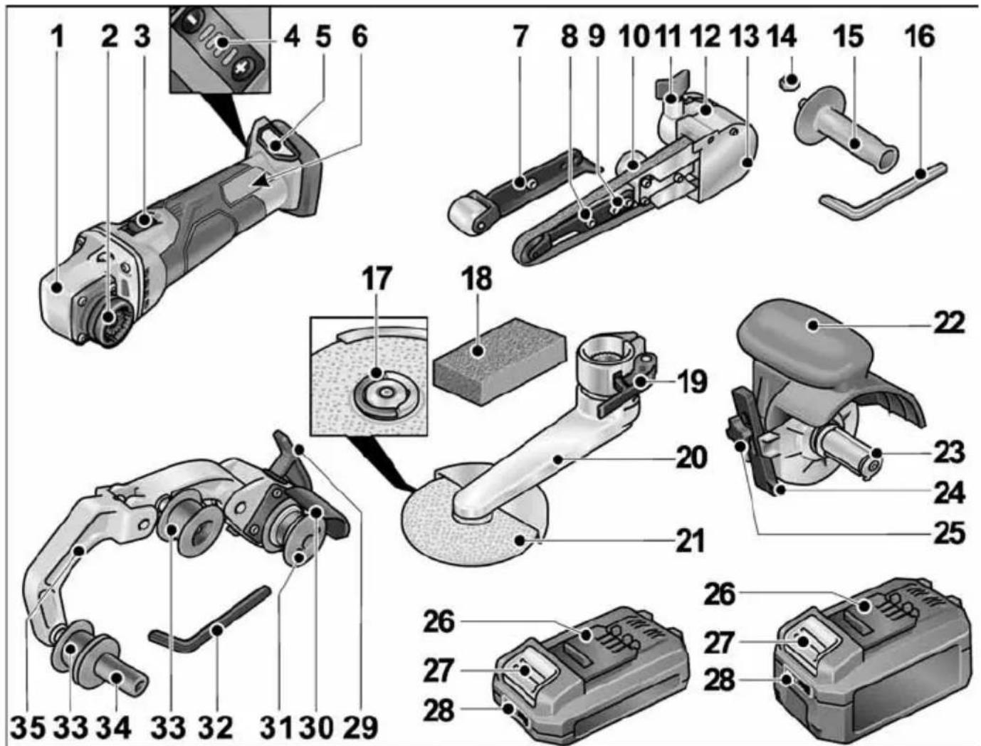
Drive unit BME 18.0-EC
1 Gear head
2 Quick-release coupling for attachments
3 Rocker switch
For switching on and off.
With detent position for non-stop operation.
4 Speed control
+/- function with 4 stages
5 Slot for battery
6 Rating plate *)
Belt file sanding attachment BF 140
7 Contact roller with sanding arm
8 Securing screw/adjusting screw for setting belt course
9 Securing screws for sanding arm
10 Eccentric screw
11 Locking screw for sanding attachment
12 Release lever for quick-release coupling
13 Housing cover
14 Hexagon nut
15 Handle
16 Allen key
Fillet weld grinding attachment LK 152
17 FixTec quick clamping nut
18 Profiling block
19 Clamping lever
20 Sanding arm
21 Sanding disc
Burnishing attachment BS 50
22 Protective hood with handle
23 Tool holder
24 Parallel guide
25 Locking screw for parallel guide and attachment
Batteries
26 Li-ion battery (2.5 Ah or 5.0 Ah)
27 Battery release button
28 State of charge indicator
Pipe belt sanding attachment BR 50
29 Clamping lever for quick-release coupling
30 Protective cover
31 Drive roller with thrust rings
32 Allen key
33 Relay roller with thrust rings
34 Handle
35 Swing arm
Spring-loaded for tensioning the sand- ing belt.
*) Not shown
Instructions for use

WARNING!
Remove the battery before carrying out any work on the power tool.
Before initial operation
Unpack the drive unit and attachments, and check that no parts are missing or were damaged during transport.

NOTE
The batteries are not fully charged on delivery. Prior to initial operation, charge the batteries fully. Refer to the charger operating manual.
Inserting/replacing the battery
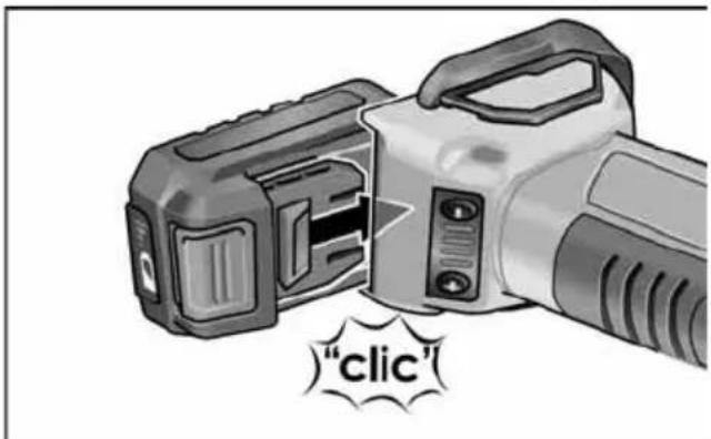
■ Press the charged battery into the power tool until it clicks into place.
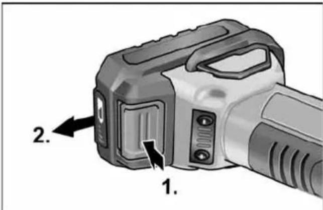
■ To remove, press the release button (1.) and pull out the battery (2.).

CAUTION!
When the device is not in use, protect the battery contacts. Loose metal parts may short-circuit the contacts; explosion and fire hazard!
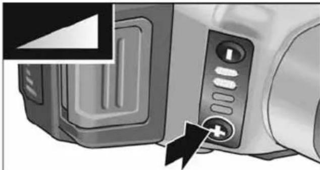
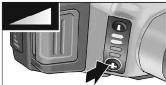
Battery state of charge
■ Press the button to check the state of charge on the state of charge indicator LEDs.
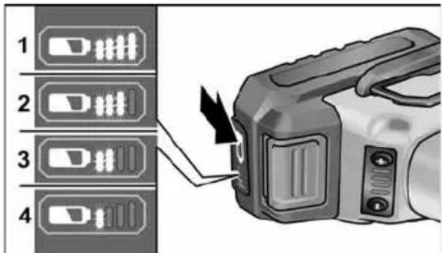
The indicator goes out after 5 seconds. If one of the LEDs flashes, the battery must be recharged. If none of the LEDs light up after the button is pressed, the battery is faulty and must be replaced.
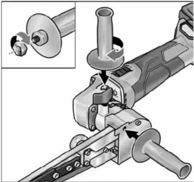
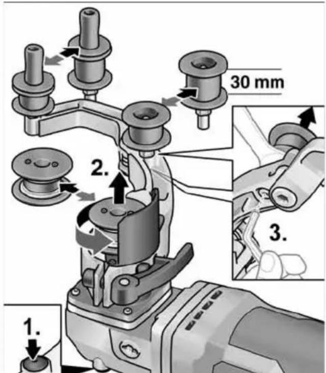
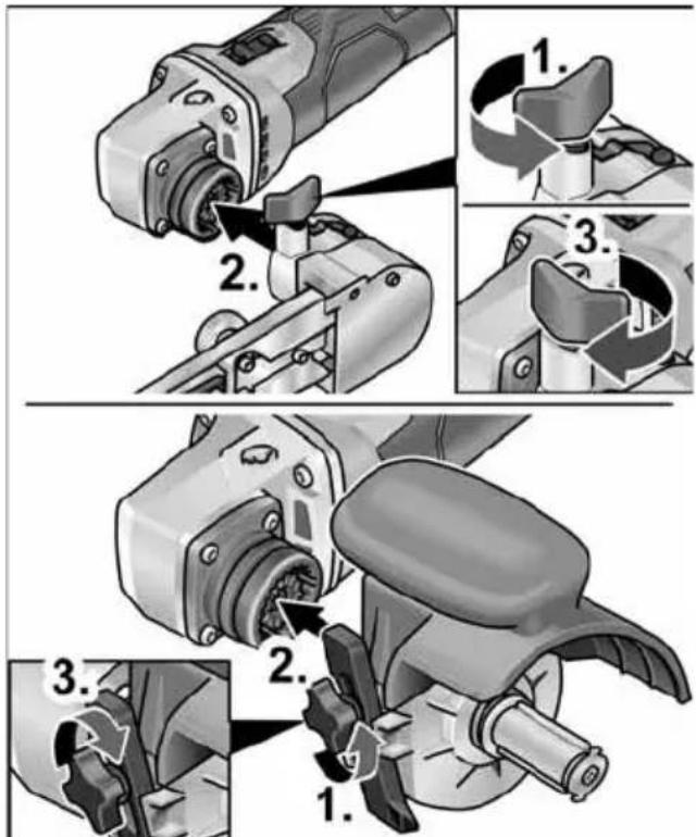
Mounting attachments
■ Place the required attachment on a level work surface with the quick-release coupling facing upwards.
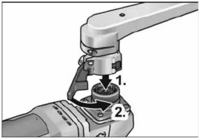
■ Place the drive unit in the required position for the attachment and press down until it engages audibly (1.).
■ Close the clamping lever (2.).
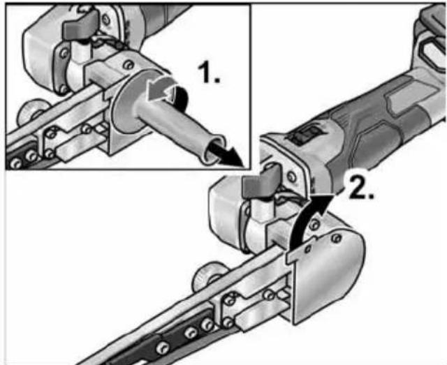
■ Open the clamping lever on the attachment (1.).
■ Place the drive unit in the required position for the attachment and press down until it engages audibly (2.).
■ Close the clamping lever (3.).
NOTE If the attachment does not audibly engages, move the spindle or drive pully of the tool a bit, so that the coupling can interlock.
■ Loosen the locking screw (1.).
■ Place the drive unit on the quick-release coupling (2.).
■ Re-tighten the locking screw (3.).
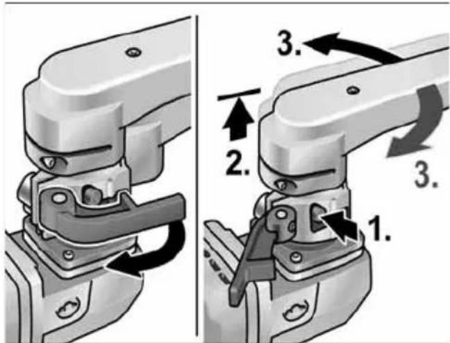
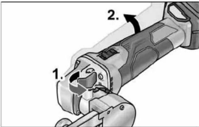
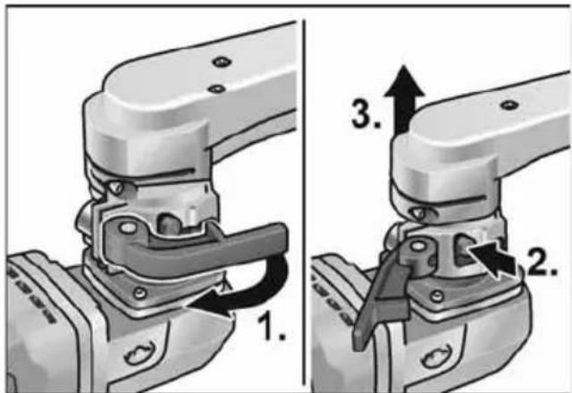
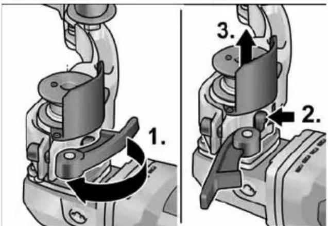
Removal of attachments
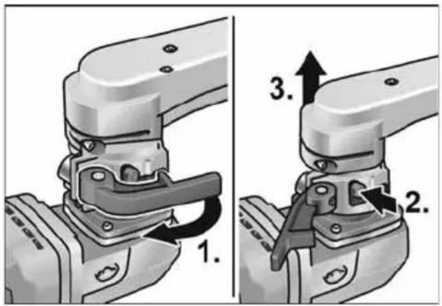
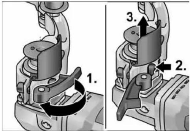
■ Open the clamping lever on the attachment (1.).
■ Press and hold down the release lever (2.).
■ Lift the drive unit off the attachment (3.).
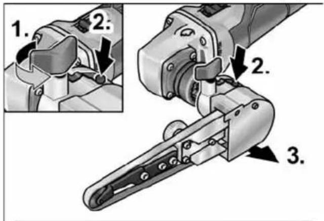

■ Loosen the locking screw on the attachment (1.).
■ Push and hold the release lever (2.).
■ Lift off the attachment (3.).
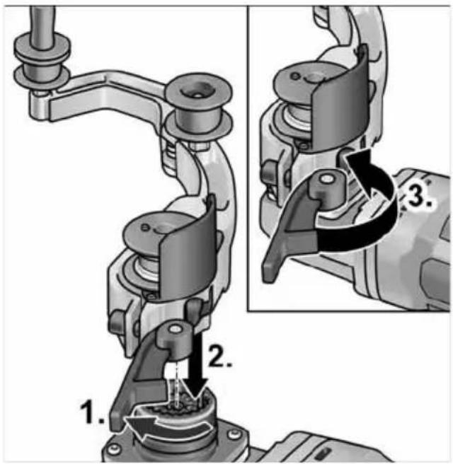
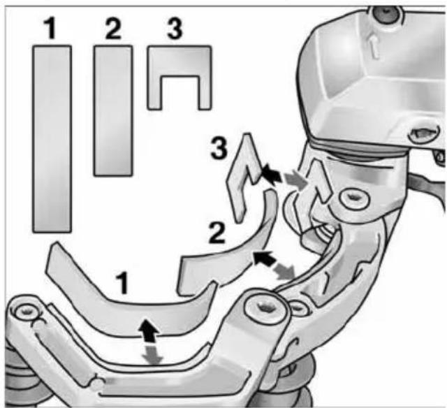
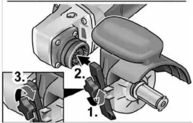
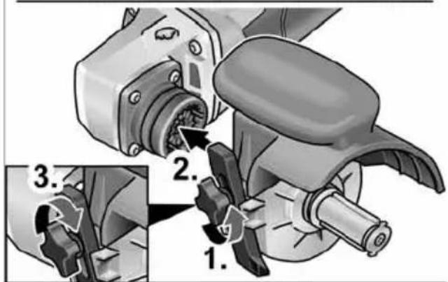
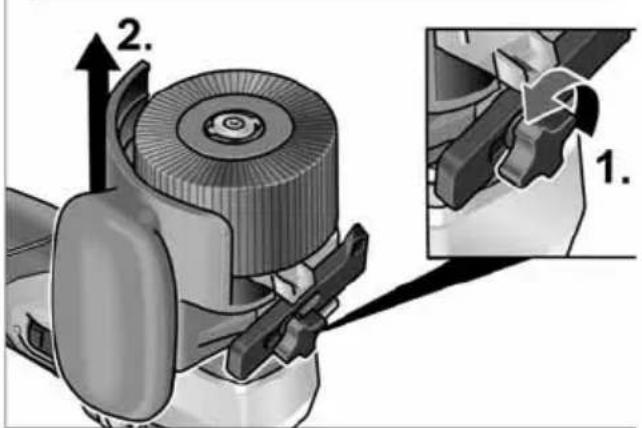
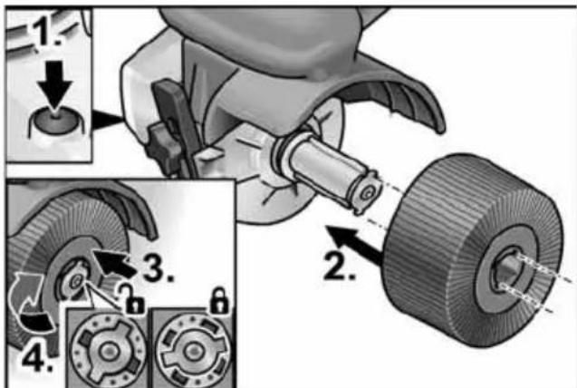
Burnishing attachment BS 50
Securing the tool
The tool holder enables the tool to be changed without any tools.
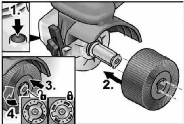
■ Remove the battery.
■ Press and hold the spindle lock (1.).
■ Push the tool or tool carrier on the tool holder (tongue and groove fitting) (2.).
■ Press the tool downwards against spring pressure (3.) and turn clockwise (4.). The tool holder is locked.
i NOTE
The width of the tool holder is 50 mm. Depending on the tool width, several tools may need to be fitted or the differences in width compensated for by means of spacer rings.
Examples:
| Polishing wheel, 50 mm wide: | 1 tool |
| Polishing mop, 10 mm wide: | 4 tools and spacer rings |
■ Switch on the power tool (without detent) and allow it to run for approx. 30 seconds. Check for imbalance and vibrations.
■ Switch off the power tool.
Using the parallel guide
The parallel guide ensures exact straight running when machining profiles.
■ Loosen the locking screw on the parallel guide (1.).
■ Adjust the parallel guide (2.).
■ Re-tighten the locking screw.
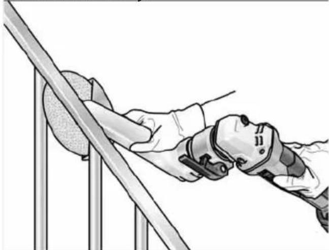
Notices for working with the burnishing attachment

CAUTION!
When it is switched off, the sanding tool continues to run briefly.
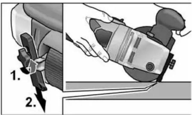
Working on level surfaces:
■ Hold the power tool firmly with both hands. For surface finishing:
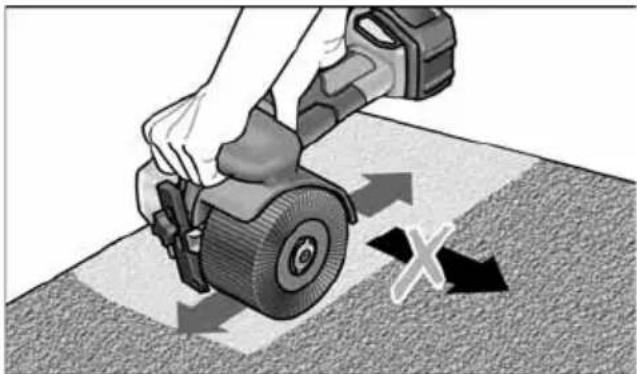
natural_image
Illustration of a hand using a tool to cut a tire on a textured surface, with directional arrows indicating motion (no text or symbols)Place the power tool carefully on the surface to be treated and guide it back and forth with linear movements.
Fillet weld grinding attachment LK 152
Changing the grinding disc
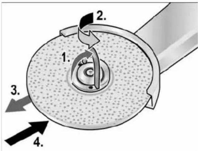
■ Remove the battery.
■ Open the FixTec quick clamping nut.
■ Open the lock for the quick clamping nut 1.).
■ Turn the quick clamping nut in anti-clock wise direction while holding the grinding disc (2.).
■ Remove the grinding disc (3.).
■ Fit a new grinding disc (4.).
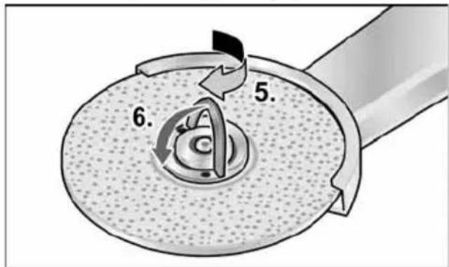
■ Tighten the quick clamping nut by turning in clockwise direction (5.) and close the lock (6.).
Swivelling the sanding arm
Notices for working with the fillet weld grinding attachment

CAUTION!
When it is switched off, the power tool continues to run briefly.
natural_image
Illustration of a person using a robotic arm to lift a horizontal bar (no text or symbols present)■ Use the sander in areas that are particularly hard to reach, e.g. tight interior angles in railing construction.
■ Do not bring the sanding plate into contact with the workpiece until the full speed of the tool has been reached.
■ To achieve good sanding results, move the sanding plate evenly over the surface to be sanded down.
■ Do not impart excessive force.
■ To achieve perfect radii, use the profiling block. Use it to profile the sanding plate.
■ When it is switched off, the sanding plate continues to run briefly.
Pipe belt sanding attachment BR 50

WARNING!
Remove the battery before carrying out any work on the power tool.
Fitting or changing the sanding belt

CAUTION!
Observe the prescribed direction of belt rotation! The direction of rotation must correspond with the arrow on the gear head.
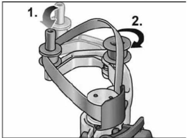
■ Remove the battery.
■ Press the swing arm in the direction of the drive roller and hold (1.).
■ Fit the sanding belt over the rollers (2.).
■ Release the swing arm.
■ Check that the belt is fitted properly on the rollers.
Mounting the handle
Bring the handle into position on the thread.
natural_image
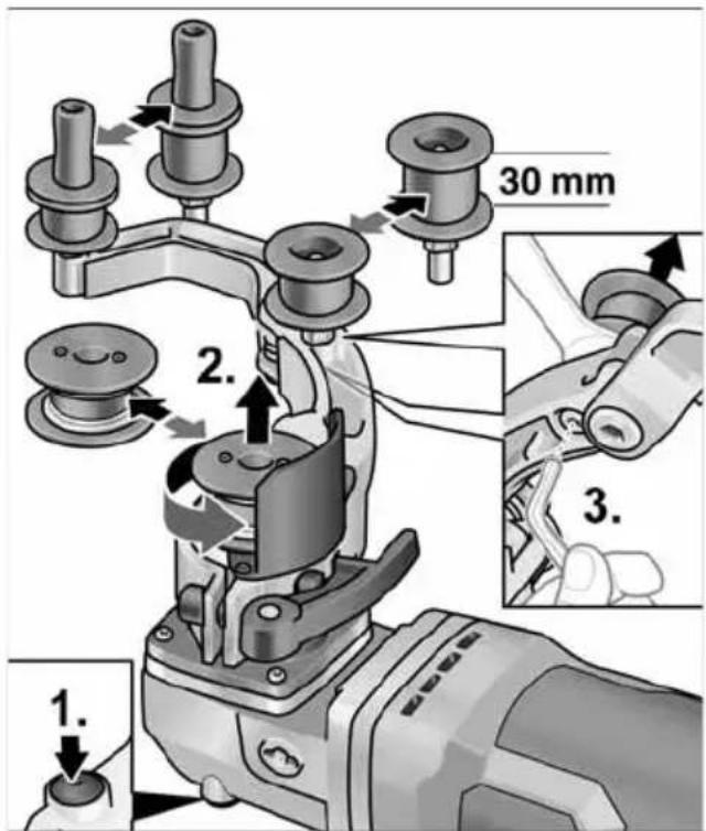
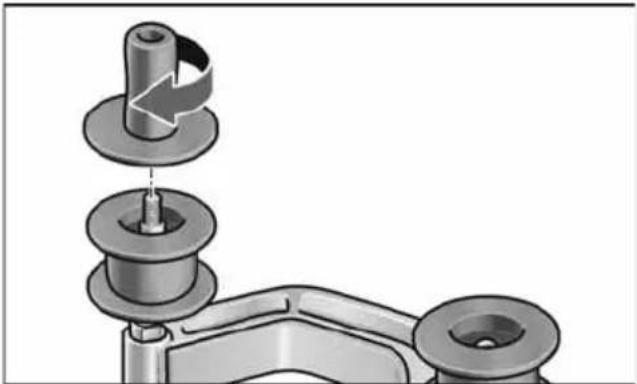
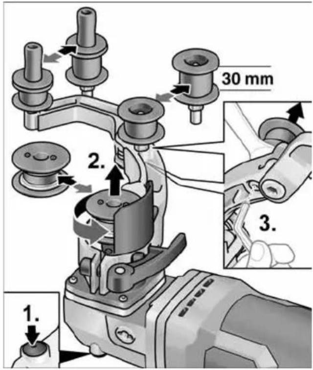
Mechanical assembly diagram showing a pin inserted into a housing component (no text or symbols)Changing the rollers

Drive roller:
■ Press and hold the spindle lock (1.).
■ Loosen the drive roller against the direction of rotation and pull off (2.).
■ Fit a new drive roller and tighten in the direction of rotation.
■ Release the spindle lock.
Relay roller:
■ Loosen the screw using a hexagon key and pull off the relay roller (3.).
■ Fit a new relay roller and tighten.
Work instructions for the pipe belt sand ing attachment

CAUTION!
When it is switched off, the sanding tool continues to run briefly.
Compared with a sanding/grinding disc, the advantages of a belt sander are as follows:
- Cool sanding
– Clean finish without scoring
– High abrading performance
– High productivity owing to large angle of contact (depending on diameter)
Sanding/grinding:

NOTE
After bringing into contact with the work piece and before switching on the machine, check that the belt is in complete contact with the rollers.
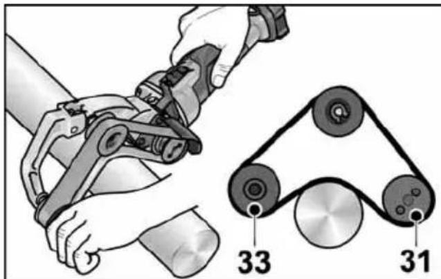
– Pipes are sanded between rollers 31 and 33.
- The angle of contact and the abrading performance can be varied by the amount of pressure applied.
- The smaller the pipe diameter, the greater the possible angle of contact. An angle of up to 270^ is possible.
Sealing:
Many manufacturers recommended sealing finished surfaces with a protective spray (see Flex stainless steel accessories).
For further information on the manufacturer's products go to www.flex-tools.com.
Belt file sanding attachment BF 140

WARNING!
Remove the battery before carrying out any work on the power tool.
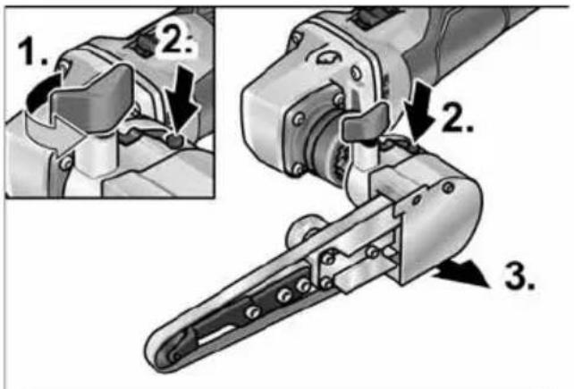
Fitting or changing the sanding belt
■ Remove the battery.
■ Remove the handle(1.).
■ Swivel the housing cover to one side (2.).
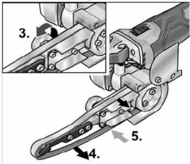
■ Turn the eccentric screw and in doing so detension the sanding belt (3.).
■ Remove the sanding belt (4.) (optional).
■ Fit a new sanding band centrally on the sanding arm (5.).
■ Tension the sanding belt by turning the ec centric screw.
■ Fold the housing cover back onto the housing.
CAUTION!
Observe the prescribed direction of belt rotation! The direction of rotation must correspond with the arrow on the gear head.
Mounting the handle
natural_image
Mechanical assembly diagram showing a tool interacting with a cylindrical component, with an inset close-up of the tool's end (no text or symbols visible)■ Secure the auxiliary handle by the thread in position 1 or 2.
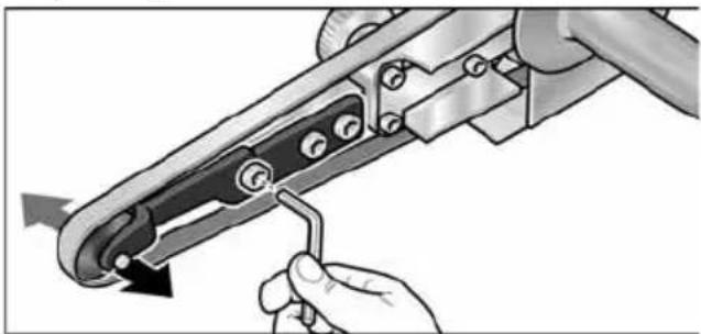
Adjusting the belt direction
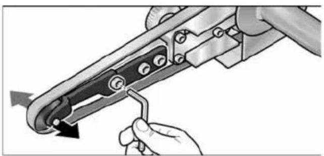
natural_image
Illustration of a hand using a tool to adjust or install a mechanical component, with no visible text or symbols.■ Use the screw at the far front of the sand ing arm to adjust the belt direction. While the belt is turning, adjust it so that the belt runs centrally over the contact roller.
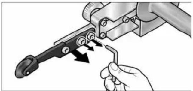
Changing the sanding arm

natural_image
Illustration of a hand using a tool to adjust a mechanical component (no text or symbols visible)■ Loosen the three securing screws to change the sanding arm.
■ Remove the sanding arm.
■ Fit a new sanding arm using the three screws.
Operating instructions
NOTE When it is switched off, the power tool continues to run briefly.
Sanding/grinding
■ After opening the locking screw (1.) the swivel arm can be tilted up to 140^ (2.). In this way, the belt file sander can also be used in areas that are difficult to reach, e.g. on the insides of pipes. ■ Vary the abrading performance by means of the contact pressure. Make sure that the contact pressure is even and not too heavy. In the event of excessive contact pressure, the sanding belt could slip off the roller.
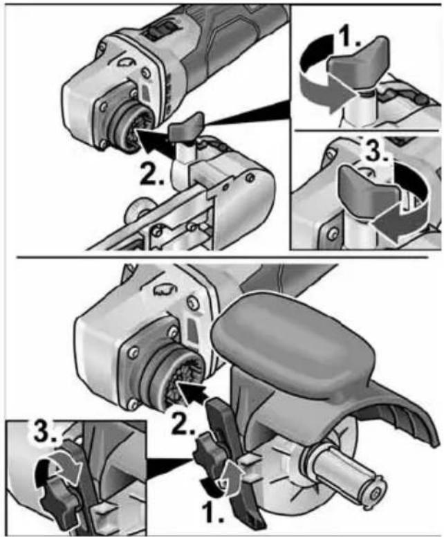
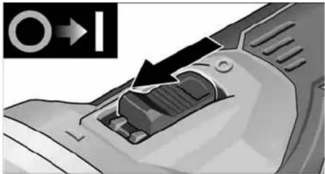
Switching on and off
Short-term operation without detent
natural_image
Close-up of a mechanical component with an arrow indicating a process or operation, no visible text or symbols.■ Push the switch forwards and hold.
■ To switch off, release the switch.
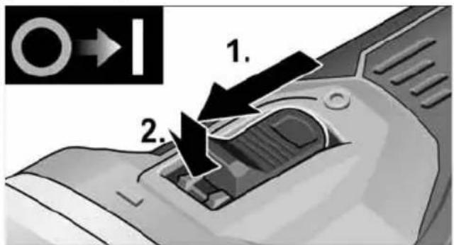
Non-stop operation with detent
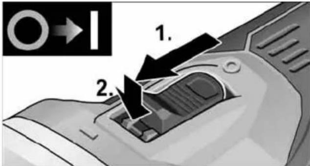
■ Push the switch forwards (1.) and engage the detent by pressing the front part (2.).
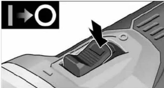
natural_image
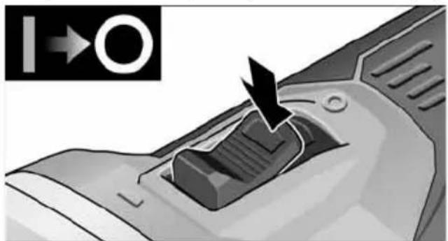
Close-up of a mechanical component with an arrow pointing to a button (no visible text or symbols)■ To switch off, release the switch by pressing the rear part.
i NOTE
If there is a power failure, the switched on power tool will not start running again.
Speed preselection
natural_image
Close-up of a microwave oven with control panel and buttons, showing a close-up of the lid (no text or symbols visible)■ To set the operating speed, press the speed control button. The speed selection remains set even after switching off.
■ Press the switch carefully to accelerate the power tool to the preselected speed.
CAUTION!
Risk of injury from disintegration of the tool. Use a tool appropriate for the task at hand.
i NOTE
Overload protection: Switches the machine off in the event of overload.
- Temperature monitoring: The machine will switch off if there is a risk of over heating.
Maintenance and care
WARNING!
Remove the battery before carrying out any work on the power tool.
Cleaning
WARNING!
When working with metals for prolonged periods, electrically conductive dust could build up inside the housing of the tool. This would impair the protective isolation! Operate the machine using an earth leakage circuit breaker (30 mA trigger current).
■ Regularly clean the power tool and ventilation slots. Frequency of cleaning is dependent on the material and duration of use.
■ Regularly blow out the housing interior and motor with dry compressed air.
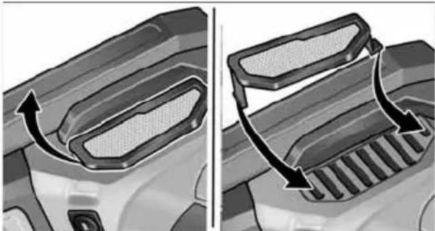
■ Clean dust filter at regular intervals.
natural_image
Two-panel illustration showing a car's side profile of the roof and grille, with arrows indicating airflow direction (no text or symbols)■ Remove dust filter and blow out with dry compressed air.
Carbon brushes
The drive unit is fitted with cut-off carbon brushes. When the cut-off carbon brushes reach their wear limit, the power tool switches off automatically.
i NOTE
Use only original parts supplied by the manufacturer for replacement purposes. The use of non-original parts will invalidate any claims under the manufacturer's warranty. When the power tool is being used, the carbon brushes can be seen sparking through the rear air inlet apertures. If the carbon brushes are sparking excessively, switch off the power tool immediately. Take the drive unit to a customer service centre authorised by the manufacturer.
Gear
i NOTE
Do not loosen the screws on the gear head during the warranty period. Failure to comply with this requirement will invalidate any claims under the manufacturer's warranty.
Repairs
Repairs may only be carried out by an authorised customer service centre.
Replacement of wear parts
The felt pad on the swing arm is subject to wear during operation of the belt sanding at tachment. Spare parts can be obtained from the manufacturer or dealer.
Spare parts and accessories
Other accessories can be found in the manufacturer's catalogues. Exploded drawings and spare-part lists can be found on our homepage: www.flex-tools.com
Disposal information
WARNING!
End-of-life power tools must be rendered inoperable before disposal.
- For mains-operated power tools, remove the mains cable.
- For battery-operated power tools, remove the battery.

EU countries only
Do not dispose of electric power tools in the household waste!
In accordance with the European directive 2012/19/EU on Waste Electrical and Electronic Equipment and its incorporation into national law, end-of-life electric power tools must be collected separately and recycled in an environmentally-friendly manner.
Recycling raw materials instead of waste disposal.
Device, accessories and packaging should be recycled in an environmentally-friendly manner. Plastic parts are identified for recycling according to material type.
WARNING!
Do not throw batteries into the household waste, fire or water. Do not open end-of-life batteries.
EU countries only: defective or end-of-life batteries must be recycled in accordance with directive 2006/66/EC.
i NOTE
Please ask your dealer about disposal options.
CE Declaration of Conformity
We hereby declare that the product described under Technical data complies with the following standards or normative documents:
EN 60745 / EN 62841 according to the provisions of directives 2014/30/EU, 2006/42/EC, 2011/65/EU.
Responsible for technical documents:
Peter Lameli Technical Head
Klaus Peter Weinper Head of Quality Department (QD)
15.12.2020
Declaration of Conformity
We as the manufacturer: FLEX
Business address: Bahnhofstr. 15,
71711 Steinheim, Germany
declare under our sole responsibility, that the product(s) described under „Technical specifications“ fulfills all the relevant provisions of The Supply of Machinery (Safety) Regulations S.I. 2008/1597 and also fulfills all the relevant provisions of the following UK Regulations:
Electromagnetic Compatibility Regulations S.I. 2016/1091, The Restriction of the Use of Certain Hazardous Substances in Electr cal and Electronic Equipment Regulations S.I. 2012/3032 and are manufactured in ac- cordance with the following designated Standards: BS EN 62841-1:2015, BS EN 62841-2-4:2014, BS EN 55014-1:2017, BS EN 55014-2:2015
Place of declaration: Steinheim, Germany.
Responsible person: Peter Lameli,
Contact details for Great Britain:
FLEX Power Tools Limited,
Unit 8 Anglo Office Park, Lincoln Road,
HP 12, 3RH Buckinghamshire,
United Kingdom

Peter Lameli
Technical Head

Klaus Peter Weinper
Head of Quality
Department (QD)
19.05.2021
Exemption from liability
The manufacturer and its agent are not liable for any damage and lost profit due to interruption in business caused by the product or by an unusable product. The manufacturer and its agent are not liable for any damage which was caused by improper use of the power tool or by use of the power tool with products from other manufacturers.
Table des matières
natural_image
Illustration of a hand using a tire to lift a car wheel, with directional arrows indicating motion (no text or symbols)natural_image
Illustration of a person using a medical or surgical device on a metal platform (no text or symbols visible)natural_image
Mechanical assembly diagram showing a pin roller being inserted into a housing (no text or symbols)natural_image
Mechanical assembly diagram showing a cutting tool with a magnified inset view of the component (no text or symbols present)natural_image
Illustration of a hand using a tool to adjust or install a mechanical component, with no visible text or symbols.natural_image
Illustration of a hand using a tool to adjust or install a mechanical component, with arrows indicating motion (no text or symbols present)natural_image
Close-up of a mechanical component with a black arrow indicating a process or operation, no visible text or symbols.natural_image
Close-up of a car's air vent with a black arrow indicating airflow direction (no text or symbols)natural_image
Close-up of a microwave oven with control panel and buttons, showing a close-up of the lid (no text or symbols visible)natural_image
Close-up of a car's front bumper with a curved arrow indicating motion (no text or symbols)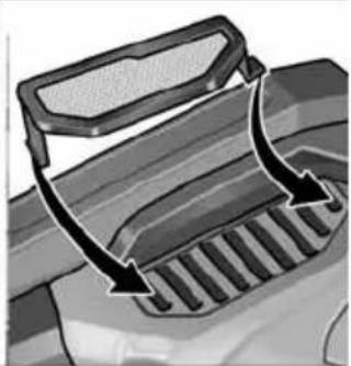
natural_image
Diagram of a vehicle's exhaust griddling with arrows indicating airflow direction (no text or symbols)
Peter Lameli
Technical Head

Klaus Peter Weinper Head of Quality Department (QD)
15/12/2020
natural_image
Illustration of a hand using a tire to lift a car wheel, with directional arrows indicating motion (no text or symbols)natural_image
Illustration of a robotic hand gripping a metal rail, no text or symbols presentnatural_image
Mechanical assembly diagram showing a mechanical component with three circular parts and a central shaft (no text or symbols)natural_image
Mechanical assembly diagram showing a cutting tool interacting with a workpiece, with an inset close-up of the tool's end (no text or symbols visible)natural_image
Illustration of a hand using a tool to adjust or install a mechanical component, with no visible text or symbols.natural_image
Illustration of a hand using a tool to adjust a mechanical component with arrows indicating motion (no text or symbols present)natural_image
Close-up of a mechanical component with an arrow indicating direction (no text or symbols visible)natural_image
Close-up of a mechanical component with a black arrow pointing to a button (no text or symbols visible)natural_image
Close-up of a microwave oven with control panel and buttons, showing a black arrow pointing to the button (no text or symbols visible)natural_image
Close-up of a car's front panel showing a mesh grille and a curved arrow indicating motion (no text or symbols)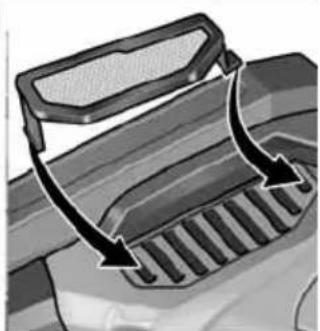
natural_image
Diagram of a vehicle's exhaust griddling with arrows indicating airflow direction (no text or symbols)
Peter Lameli
Technical Head
Klaus Peter Weinper Head of Quality Department (QD)
15/12/2020
natural_image
Illustration of a hand using a roller to cut a tire on a textured surface, with directional arrows indicating motion (no text or symbols)natural_image
Illustration of a person using a robotic arm to lift a rope on a metal railing (no text or symbols)natural_image
Mechanical assembly diagram showing a mechanical component with three parts and a directional arrow indicating motion (no text or symbols)natural_image
Mechanical assembly diagram showing a tool interacting with a workpiece, with an inset close-up of the component (no text or symbols visible)natural_image
Illustration of a hand using a tool to adjust or install a mechanical component, with no visible text or symbols.natural_image
Illustration of a hand using a tool to adjust or install a mechanical component, with arrows indicating motion (no text or symbols present)natural_image
Close-up of a mechanical component with an arrow indicating a process or operation, no visible text or symbols.natural_image
Close-up of a mechanical component with an arrow pointing to a button, no visible text or symbolsnatural_image
Close-up of a microwave oven with control buttons and a plus button, no visible text or symbolsnatural_image
Close-up of a car's front bumper with an arrow indicating direction (no text or symbols)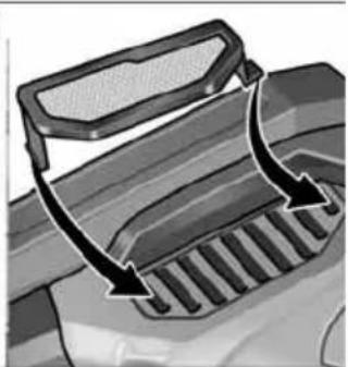
natural_image
Diagram of a vehicle's exhaust griddling with arrows indicating airflow direction (no text or symbols)Peter Lameli Technical Head

Klaus Peter Weinper Head of Quality Department (QD)
15/12/2020
natural_image
Illustration of a hand using a power tool to cut a tire on a textured surface, with directional arrows indicating motion (no text or symbols)natural_image
Illustration of a person using a robotic device on a metal platform (no text or symbols)natural_image
Mechanical assembly diagram showing a mechanical component with three parts and a directional arrow indicating rotation (no text or symbols)Substituir os rolos

Rolo de acionamento:
natural_image
Mechanical assembly diagram showing a tool interacting with a workpiece, with an inset close-up of the component (no text or symbols visible)natural_image
Illustration of a hand using a tool to adjust or install a mechanical component, with no visible text or symbols.natural_image
Illustration of a hand using a tool to adjust or install a mechanical component, with arrows indicating motion (no text or symbols present)natural_image
Close-up of a mechanical component with a black arrow indicating a process step, no visible text or symbolsnatural_image
Close-up of a mechanical component with a black arrow pointing to a button (no text or symbols visible)natural_image
Close-up of a kitchen microwave oven with control panel and buttons (no visible text or symbols)natural_image
Close-up of a car's front bumper with an arrow indicating direction (no text or symbols)
natural_image
Diagram of a vehicle's roof grating system with arrows indicating direction (no text or symbols)EN 60745 de acordo com as determinações das directivas 2014/30/UE, 2006/42/CE, 2011/65/UE.
Peter Lameli Technical Head

Klaus Peter Weinper Head of Quality Department (QD)
15/12/2020
natural_image
Illustration of a hand using a tool to cut a tire on a textured surface, with directional arrows indicating motion (no text or symbols)natural_image
Illustration of a person using a robotic device on a metal platform (no text or symbols)natural_image
Mechanical assembly diagram showing a pin roller being inserted into a bracket (no text or symbols)Rollen vervangen

Aandrijfrol:
natural_image
Mechanical assembly diagram showing a cutting tool with a workpiece and a close-up inset of the component (no text or symbols visible)natural_image
Illustration of a hand using a tool to adjust or install a mechanical component, with no visible text or symbols.natural_image
Illustration of a hand using a tool to adjust a mechanical component with arrows indicating motion (no text or symbols present)natural_image
Close-up of a mechanical component with a black arrow indicating a process step, no visible text or symbolsnatural_image
Close-up of a mechanical component with a black arrow pointing to a button, no visible text or symbolsnatural_image
Close-up of a microwave oven with control panel and buttons, showing a black arrow pointing to the button (no text or symbols visible)Peter Lameli Technical Head

Klaus Peter Weinper Head of Quality Department (QD)
15-12-2020
Drivenhed BME 18.0-EC
1 Gearhoved
2 Lynkobling til forsatser
3 Vippekontakt
natural_image
Illustration of a hand using a tire to lift a textured surface with directional arrows indicating motion (no text or symbols)natural_image
Illustration of a robotic arm gripping a metal railing (no text or symbols)natural_image
Mechanical assembly diagram showing a mechanical component with three circular parts and a central shaft (no text or symbols)Skift af ruller
Drivrulle:
■ Udtag akku.
natural_image
Mechanical assembly diagram showing a cutting tool with a magnified inset view of the component (no text or symbols present)natural_image
Illustration of a hand using a tool to adjust or install a mechanical component, with no visible text or symbols.natural_image
Illustration of a hand using a tool to adjust or install a mechanical component, with arrows indicating motion (no text or symbols present)natural_image
Close-up of a mechanical component with an arrow indicating direction, no visible text or symbols■ Skub vippekontakten fremad og hold den fast.
■ Slip vippekontakten for at slukke.
natural_image
Diagram of a mechanical component with an arrow indicating direction (no text or symbols present)■ Frigør vippekontakten ved at trykke på bagerste ende for at slukke.
i BEMAERK
natural_image
Close-up of a microwave oven with control panel and door (no visible text or symbols)natural_image
Diagram showing two views of a vehicle's front panel with mesh and grating surfaces, no text or symbols present.Peter Lameli Technical Head
Klaus Peter Weinper Head of Quality Department (QD)
15-12-2020
Drivenhet BME 18.0-EC
1 Drivhode
2 Hurtigkobling for forsatser
3 Skyvebryter
■ Løsne låseskruen på forsatsen (1.).
■ Trykk på låsespaken, og hold den inntrykt (2.).
■ Løft forsatsen (3.).
Fest fast verktøyet
natural_image
Illustration of a hand using a tool to cut a tire on a textured surface, with directional arrows indicating motion (no text or symbols)natural_image
Illustration of a robotic hand gripping a metal rod, no text or symbols presentnatural_image
Mechanical assembly diagram showing a pin adjustment mechanism with two circular components and a central shaft (no text or labels)Skifte hjul

Drivhjul:
natural_image
Mechanical assembly diagram showing a tool interacting with a workpiece, with no visible text or symbols.natural_image
Illustration of a hand using a tool to adjust or install a mechanical component, with no visible text or symbols.natural_image
Illustration of a hand using a tool to adjust or install a mechanical component, with arrows indicating motion (no text or symbols present)■ For skift av slipearmen løsnes de tre festeskruene.
■ Ta av slipearmen.
■ Fest på en ny slipearm med hjelp av de tre skruene.
Arbeidstips
natural_image
Close-up of a mechanical component with a black arrow indicating a process or operation, no visible text or symbols.natural_image
Close-up of a mechanical component with an arrow pointing to a button, no visible text or symbolsnatural_image
Close-up of a microwave oven with control panel and buttons, showing a close-up of the lid (no text or symbols visible)natural_image
Close-up of a car's front bumper with a curved arrow indicating motion (no text or symbols)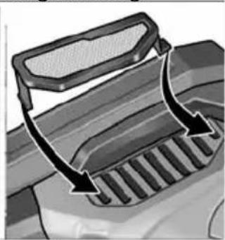
natural_image
Diagram of a vehicle's intake manifold with arrows indicating direction (no text or symbols)Peter Lameli Technical Head

Klaus Peter Weinper Head of Quality Department (QD)
15.12.2020
Drivenhet BME 18.0-EC
1 Växelhus
natural_image
Illustration of a hand using a tool to lift a tire on a textured surface, with directional arrows indicating motion (no text or symbols)natural_image
Illustration of a robotic hand gripping a large cylindrical object on a metal railing (no text or symbols visible)natural_image
Mechanical assembly diagram showing a mechanical component with three parts and a directional arrow indicating motion (no text or symbols)Byta rullar

Drivrulle:
natural_image
Mechanical assembly diagram showing a cutting tool and a workpiece with a cylindrical component, no text or symbols present.natural_image
Illustration of a hand using a tool to adjust or install a mechanical component, with no visible text or symbols.natural_image
Illustration of a hand using a tool to adjust a mechanical component with arrows indicating motion (no text or symbols present)natural_image
Close-up of a mechanical component with an arrow indicating direction, no visible text or symbolsnatural_image
Close-up of a mechanical component with a black arrow pointing to a textured area, no visible text or symbols.natural_image
Close-up of a microwave oven with control panel and buttons, showing a close-up of the lid (no text or symbols visible)natural_image
Two-panel illustration showing a car's side profile of the roof and grille, with arrows indicating direction (no text or symbols)Peter Lameli Technical Head
Klaus Peter Weinper Head of Quality Department (QD)
2020-12-15
natural_image
Illustration of a hand using a power tool to cut a tire on a textured surface, with directional arrows indicating motion (no text or symbols)natural_image
Illustration of a robotic hand gripping a metal rod, no text or symbols presentnatural_image
Mechanical assembly diagram showing a clamping mechanism with three components (no text or labels)Rullien vaihto

Vetorulla:
natural_image
Mechanical assembly diagram showing a tool interacting with a workpiece, with no visible text or symbols.natural_image
Illustration of a hand using a tool to adjust or install a mechanical component, with no visible text or symbols.natural_image
Illustration of a hand using a tool to adjust or install a mechanical component with arrows indicating motion (no text or symbols present)natural_image
Close-up of a mechanical component with a black arrow indicating direction, no visible text or symbolsnatural_image
Close-up of a car's dashboard handle with a black arrow pointing to the left side (no text or symbols visible)natural_image
Close-up of a microwave oven with control panel and buttons, showing a close-up of the lid (no text or symbols visible)natural_image
Two-panel illustration showing car door frame and side profile of a mesh grille with arrows indicating direction (no text or symbols)
Peter Lameli Technical Head

Klaus Peter Weinper Head of Quality Department (QD)
15.12.2020
natural_image
Illustration of a hand using a tire to lift a surface with directional arrows indicating motion (no text or symbols)natural_image
Illustration of a robotic arm gripping a metal rod, no text or symbols presentnatural_image
Mechanical assembly diagram showing a pin roller being inserted into a housing (no text or symbols)Αλλαγή κυλίνδρων

natural_image
Mechanical assembly diagram showing a tool interacting with a workpiece, with an inset close-up of the component (no text or symbols visible)natural_image
Illustration of a hand using a tool to adjust or install a mechanical component, with no visible text or symbols.natural_image
Illustration of a hand using a tool to adjust a mechanical component (no text or symbols visible)natural_image
Close-up of a mechanical component with an arrow indicating direction, no visible text or symbolsnatural_image
Close-up of a mechanical component with an arrow pointing to a button (no text or symbols visible)natural_image
Close-up of a microwave oven with control panel and buttons, showing a close-up of the lid (no text or symbols visible)natural_image
Two-panel illustration showing car exterior and side mirror components with arrows indicating rotation (no text or symbols)Peter Lameli Technical Head
Klaus Peter Weinper Head of Quality Department (QD)
15/12/2020
natural_image
Illustration of a hand using a power tool to cut a tire on a textured surface, with directional arrows indicating motion (no text or symbols)natural_image
Illustration of a robotic hand reaching toward a rail railing (no text or symbols)natural_image
Mechanical assembly diagram showing a clamping mechanism with no visible text or symbolsnatural_image
Mechanical assembly diagram showing a cutting tool and a workpiece with a cylindrical component, no text or symbols present.natural_image
Illustration of a hand using a tool to adjust or install a mechanical component, with no visible text or symbols.natural_image
Illustration of a hand using a tool to adjust a mechanical component (no text or symbols visible)natural_image
Close-up of a mechanical component with an arrow indicating direction, no visible text or symbolsnatural_image
Close-up of a mechanical component with an arrow pointing to a button (no text or symbols visible)natural_image
Close-up of a microwave oven with control panel and buttons, showing a close-up of the lid (no text or symbols visible)natural_image
Close-up of a car's front bumper with a curved arrow indicating direction (no text or symbols)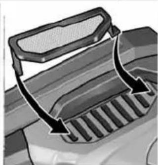
natural_image
Diagram of a vehicle's exhaust grating mechanism with arrows indicating flow direction (no text or symbols)Peter Lameli Technical Head
Klaus Peter Weinper
Head of Quality
Department (QD)
15.12.2020
natural_image
Illustration of a hand using a power tool to cut a tire on a textured surface, with directional arrows indicating motion (no text or symbols)natural_image
Illustration of a robotic hand gripping a metal rod, no text or symbols presentnatural_image
Mechanical assembly diagram showing a mechanical component with three circular parts and a central shaft (no text or symbols)Wymiana rolek

Rolka napędowa:
natural_image
Mechanical assembly diagram showing a cutting tool with a magnified inset view of the component (no text or symbols present)natural_image
Illustration of a hand using a tool to adjust or install a mechanical component, with no visible text or symbols.natural_image
Illustration of a hand using a tool to adjust a mechanical component (no text or symbols visible)natural_image
Close-up of a mechanical component with an arrow indicating a process or operation, no visible text or symbols.natural_image
Close-up of a mechanical component with an arrow pointing to a button, no visible text or symbolsnatural_image
Close-up of a microwave oven with control panel and buttons, showing a close-up of the lid (no text or symbols visible)natural_image
Two-panel illustration showing a car's side profile of the roof and grille, with arrows indicating airflow direction (no text or symbols)2014/30/UE, 2006/42/WE, 2011/65/UE.
Klaus Peter Weinper
Head of Quality
Department (QD)
15.12.2020
natural_image
Illustration of a hand using a tool to lift a tire on a textured surface, with directional arrows indicating motion (no text or symbols)natural_image
Illustration of a robotic hand gripping a metal rod against a rail, no text or symbols presentnatural_image
Mechanical assembly diagram showing a pin inserted into a housing component (no text or symbols)Görgőcsere

Meghajtógörgő:
natural_image
Mechanical assembly diagram showing a tool interacting with a workpiece, with an inset close-up of the component (no text or symbols visible)natural_image
Illustration of a hand using a tool to adjust or install a mechanical component, with no visible text or symbols.natural_image
Illustration of a hand using a manual tool to adjust or install a mechanical component, with arrows indicating motion (no text or symbols present)natural_image
Close-up of a mechanical component with a black arrow indicating a process step, no visible text or symbolsnatural_image
Close-up of a mechanical component with a black arrow pointing to a button, no visible text or symbolsnatural_image
Close-up of a microwave oven with control panel and buttons, showing a close-up of the lid (no text or symbols visible)natural_image
Close-up of a car's front bumper with an arrow indicating direction (no text or symbols)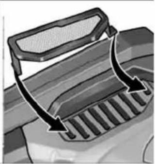
natural_image
Diagram of a vehicle's exhaust griddling with arrows indicating airflow direction (no text or symbols)
Peter Lameli
Technical Head

Klaus Peter Weinper Head of Quality Department (QD)
15.12.2020
Pohonná jednotka BME 18.0-EC
natural_image
Illustration of a hand using a tire to lift a car wheel, with directional arrows indicating motion (no text or symbols)natural_image
Illustration of a person using a robotic arm to lift a horizontal bar (no text or symbols present)natural_image
Mechanical assembly diagram showing a mechanical component with three circular parts and a central shaft (no text or symbols)Výměna válečků
Hnací váleček:
natural_image
Mechanical assembly diagram showing a tool interacting with a workpiece, with no visible text or symbols.natural_image
Mechanical assembly diagram showing a hand turning a tool into a mechanical component (no text or symbols visible)natural_image
Illustration of a hand using a tool to adjust a mechanical component with arrows indicating motion (no text or symbols present)natural_image
Close-up of a mechanical component with a black arrow indicating a process or operation, no visible text or symbols.natural_image
Close-up of a mechanical component with a black arrow pointing to a button (no text or symbols visible)natural_image
Close-up of a microwave oven with control panel and buttons, showing a close-up of the lid (no text or symbols visible)natural_image
Two-panel illustration showing car door trim and grille adjustment, with arrows indicating direction of change (no text or symbols)Peter Lameli Technical Head
Klaus Peter Weinper Head of Quality Department (QD)
15.12.2020
Hnacia jednotka BME 18.0-EC
■ Otvorte upínaciu páčku na nadstavci (1.).
■ Hnaciu jednotku nasadte v požadovanej polohe k nadstavcu a zatlačte nadol tak, aby počuteľne zapadla (2.).
■ Zatvorte upínaciu páčku (3.).
i UPOZORNENIE
■ Uvoľnite aretačnú skrutku na nadstavci (1.).
■ Stlačte odblokovaciu páčku a držte ju stlačenú (2.).
■ Zdvihnite nadstavec (3.).
Upevnenie nástroja
natural_image
Illustration of a hand using a power tool to lift a tire, with arrows indicating motion direction (no text or symbols)natural_image
Illustration of a robotic hand gripping a metal rod against a rail, with no visible text or symbols.natural_image
Mechanical assembly diagram showing a pulley mechanism with three components (no text or labels)Výmena kladky

Hnacia kladka:
natural_image
Mechanical assembly diagram showing a cutting tool with a magnified inset view of the component (no text or symbols present)natural_image
Illustration of a hand using a tool to adjust or install a mechanical component, with no visible text or symbols.natural_image
Illustration of a hand using a tool to adjust or install a mechanical component, with arrows indicating motion (no text or symbols present)natural_image
Close-up of a mechanical component with an arrow indicating direction, no visible text or symbolsnatural_image
Close-up of a mechanical component with an arrow pointing to a button, no visible text or symbolsnatural_image
Close-up of a microwave oven with control panel and buttons, showing a close-up of the lid (no text or symbols visible)natural_image
Close-up of a car's front bumper with a curved arrow indicating direction (no text or symbols)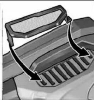
natural_image
Diagram of a vehicle's intake manifold with arrows indicating direction (no text or symbols)Peter Lameli Technical Head
Klaus Peter Weinper Head of Quality Department (QD)
15.12.2020
Pogonska jedinica BME 18.0-EC
1 Glava prijenosnika
2 Brza spojka za nastavke
3 Klizač prekidača
■ Otvorite polugu za zatezanje na nastavku (1.).
■ Pogonsku jedinicu postavite u željeni položaj na nastavak i pritišćite prema dolje dok čujno ne uskoči (2.).
■ Zatvorite polugu za zatezanje (3.).
i NAPUTAK
Ako se nastavak čujno ne uglavi, lagano zakrenite vreteno alata ili pogonski valjak nastavka kako bi spojka mogla zahvatiti.
- Otpustite vijak za fiksiranje (1.). - Pogonsku jedinicu stavite na brzu spojku (2.). - Ponovno pritegnite vijak za zaključavanje (3.).
Demontaža nastavaka
■ Otvorite polugu za zatezanje na nastavku (1.).
■ Pritisnite polugu za deblokadu i čvrsto ju držite (2.).
■ Skinite pogonsku jedinicu sa nastavka (3.).
■ Otpustite vijak za fiksiranje na nastavku (1.).
■ Pritisnite polugu za deblokadu i držite je pritisnutu (2.).
■ Podignite nastavak (3.).
natural_image
Illustration of a hand using a tire to lift a textured surface with directional arrows indicating motion (no text or symbols)Upute za rad s nastavkom žlijebne brusilice
natural_image
Illustration of a robotic arm gripping a metal rod (no text or symbols present)■ Brusilicu upotrebljavajte na teško pristupačnim mjestima kao što su npr. jako šiljasti unutrašnji kutovi na ogradama.
■ Brusni tanjur stavite na izradak kada alat postigne puni broj okretaja.
■ Za dobre rezultate brušenja ravnomjerno pomičite brusni tanjur po površini koju brusite.
■ Nemojte vršiti prejaki pritisak.
■ Za postizanje preciznih radijusa koristite kamen za profiliranje. Njime isprofilirajte brusnu ploču.
■ Nakon isključivanja brusna ploča još kratko vrijeme nastavlja s radom.
Nastavak trakaste brusilice za cijevi BR 50

POZOR!
Prije svih radova na električnom alatu izvadite akumulator iz alata.
natural_image
Mechanical assembly diagram showing a mechanical component with three circular parts and a central shaft (no text or symbols)Zamjena valjaka

Pogonski valjak:
■ Pritisnite blokadu vretena i držite je pritisnutu (1.).
■ Otpustite pogonski valjak u smjeru suprotnom od kazaljke na satu i izvucite ga (2.).
■ Stavite novi pogonski valjak i okrenite u smjeru kazaljke na satu.
■ Otpustite blokadu vretena.
Zakretni valjak:
■ Vijak otpustite imbus ključem i izvucite zakretni valjak (3.).
■ Stavite novi zakretni valjak i zategnite.
Upute za rad nastavka trakaste brusilice za cijevi

OPREZ!
■ Ekscentrični vijak okrenite i tako otpustite brusnu traku (3.).
■ Skinite brusnu traku (4.) (opcionalno).
■ Navucite novu brusnu traku na sredinu brusne ruke (5.).
■ Brusnu traku zategnite okretanjem ekscentričnog vijka.
■ Pokrov kućišta ponovno zaklopite na kućište.

OPREZ!
natural_image
Mechanical assembly diagram showing a cutting tool with a magnified inset view of its work (no text or symbols present)■ Dodatnu ručku pričvrstite na navoj u položaj 1 ili 2.
natural_image
Illustration of a hand using a tool to adjust or install a mechanical component, with no visible text or symbols.■ Pomoću prednjeg vijka na brusnoj ruci namjestite kretanje trake. Kad se traka kreće, postavku odaberite tako da traka prolazi u sredini preko potisnog valjka.
Zamjena brusne ruke
natural_image
Illustration of a hand using a tool to adjust or install a mechanical component, with arrows indicating motion (no text or symbols present)natural_image
Close-up of a mechanical component with a black arrow pointing to a section, no visible text or symbols■ Klizač prekidača gurnuti prema naprijed i čvrsto držati.
natural_image
Close-up of a mechanical component with a black arrow pointing to a button (no visible text or symbols)■ Radi isključivanja ozibnu sklopku deblokirati pritiskom na zadnji kraj.
i NAPUTAK
Nakon nestanka struje uključeni se aparat ne pokreće ponovno.
Odabir broja okretaja
natural_image
Close-up of a microwave oven with control panel and buttons, showing a black arrow pointing to the button (no text or symbols visible)■ Kako biste namjestili radnu brzinu, pritisnite tipku za regulaciju broja okretaja. Odabrana brzina ostaje pohranjena čak i pri isključivanju.
natural_image
Two-panel illustration showing a car's front and side views of a mesh grille (no text or symbols)- Izvadite filtar za prašinu i ispušite suhim komprimiranim zrakom.
Ugljene četkice
Peter Lameli Technical Head
Klaus Peter Weinper Head of Quality Department (QD)
15.12.2020
Pogonska enota BME 18.0-EC
1 Glava gonila
2 Hitra sklopka za nastavke
3 Prekucno stikalo
Za vklop in izklop.
■ Sprostite pritrdilni vijak na nastavku (1.).
■ Pritisnite ročico za odklop in jo držite pritisnjeno (2.).
■ Dvignite nastavek (3.).
Pritrditev nastavka
Vpenjalo omogoča menjavo nastavkov brez pribora.
■ Odstranite akumulatorsko baterijo.
■ Pritisnite in držite zaporo vretena (1.).
■ Nastavek oz. nosilec nastavka namestite na vpenjalo (vez utora in peresa) (2.).
■ Nastavek potisnite proti vzmeti navzdol (3.) in ga obrnite v smeri urnega kazalca (4.). Vpenjalo je zataknjeno.

OPOMBA
natural_image
Illustration of a hand using a tool to lift a tire on a textured surface, with directional arrows indicating motion (no text or symbols)■ Električno orodje previdno postavite na površino, ki jo želite obdelati, in ga z vzporednimi pomiki premikajte naprej in nazaj.
Navodila za delo z nastavkom za brušenje zvarov

POZOR!
natural_image
Illustration of a robotic arm gripping a metal rod (no text or symbols present)natural_image
Mechanical assembly diagram showing a pin inserted into a housing with two washers (no text or symbols)Zamenjava valjev

Pogonski valj:
■ Pritisnite in držite zaporo vretena (1.).
■ Pogonski valj sprostite tako, da ga zavrtite v levo in ga snamete (2.).
■ Namestite nov pogonski valj in ga pritrdite tako, da ga zavrtite v desno.
■ Izpustite zaporo vretena.
■ Odstranite akumulatorsko baterijo.
■ Snemite ročaj (1.).
■ Zavrtite ekscentrični vijak, da sprostite brusilni trak (3.).
■ Snemite brusilni trak (4.) (dodatna oprema).
■ Na sredino brusilne roke namestite nov brusilni trak (5.).
■ Zavrtite ekscentrični vijak, da napnete brusilni trak.
■ Pokrov ohišja znova nataknite na ohišje.
POZOR!
natural_image
Mechanical assembly diagram showing a tool interacting with a workpiece, with an inset close-up of the component (no text or symbols visible)natural_image
Illustration of a hand using a tool to adjust or install a mechanical component, with no visible text or symbols.natural_image
Illustration of a hand using a tool to adjust or install a mechanical component, with arrows indicating motion (no text or symbols present)■ Za menjavo brusilne roke sprostite tri pritrdilne vijake.
■ Snemite brusilno roko.
■ S tremi vijaki pritrdite novo brusilno roko.
Navodila za delo
natural_image
Close-up of a mechanical component with an arrow indicating direction, no visible text or symbols■ Prekucno stikalo potisnite naprej in ga pridržite.
■ Za izklop prekucno stikalo izpustite.
Neprekinjeno delovanje z uporabo prekucnega stikala
■ Prekucno stikalo potisnite naprej (1.) in ga s pritiskom na sprednji del zaskočite (2.).
natural_image
Close-up of a mechanical component with a black arrow pointing to a textured area, no visible text or symbols.■ Za izklop pritisnite na zadnji del prekucnega stikala, tako da sprostite zaporo.
i OPOMBA
natural_image
Close-up of a microwave oven with control buttons and a plus button, no visible text or symbolsnatural_image
Two-panel illustration showing a car's side profile and side profile of the roof cover (no text or symbols)■ Snemite filter za prah in ga izpihajte s suhim stisnjenim zrakom.
Ogljikove ščetke
Peter Lameli Technical Head
Klaus Peter Weinper Head of Quality Department (QD)
15.12.2020
Unitate de actionare BME 18.0-EC
natural_image
Illustration of a hand using a brake roller to lift a textured surface with directional arrows indicating motion (no text or symbols)natural_image
Illustration of a robotic hand gripping a metal rod, no text or symbols presentnatural_image
Mechanical assembly diagram showing a pin inserted into a housing component (no text or symbols)Înlocuirea rolelor
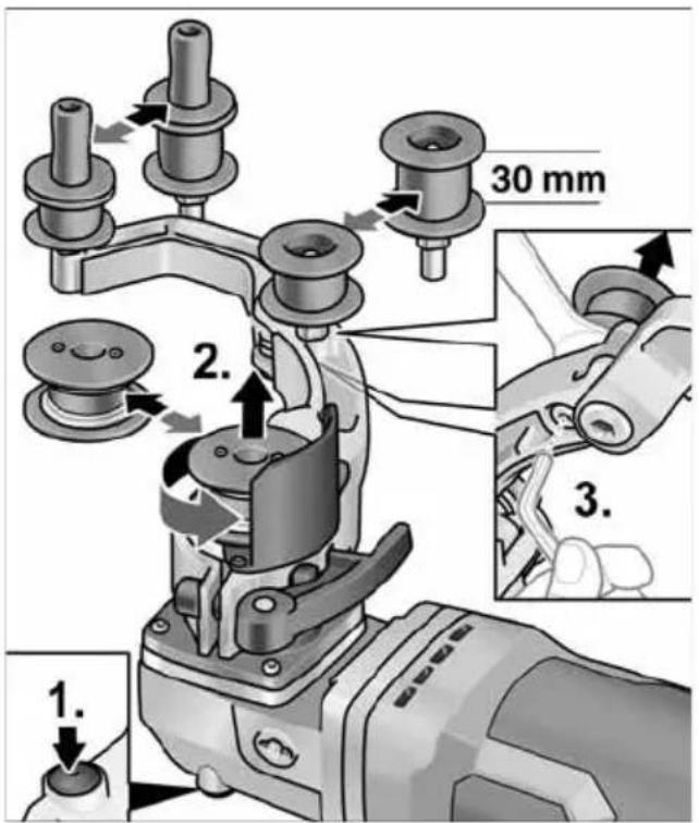
Rola de actionare:
natural_image
Mechanical assembly diagram showing a cutting tool and a workpiece with a magnified inset (no text or symbols)natural_image
Illustration of a hand using a tool to adjust or install a mechanical component, with no visible text or symbols.natural_image
Illustration of a hand using a tool to adjust or install a mechanical component, with arrows indicating motion (no text or symbols present)natural_image
Close-up of a mechanical component with a black arrow indicating a process or operation, no visible text or symbols.natural_image
Close-up of a mechanical component with a black arrow pointing to a button, no visible text or symbolsnatural_image
Close-up of a microwave oven with a control panel and indicator lights (no visible text or symbols)natural_image
Close-up of a car's front bumper with an arrow indicating direction (no text or symbols)
natural_image
Diagram of a vehicle's rear grille with arrows indicating direction (no text or symbols)EN 60745 / EN 62841 conform prevederilor Directivei 2014/30/UE, 2006/42/CE, 2011/65/UE.
Responsabili pentru documente tehnice: FLEX-Elektrowerkzeuge GmbH, R & D Bahnhofstrasse 15, D-71711 Steinheim/Murr

Peter Lameli Technical Head
Klaus Peter Weinper Head of Quality Department (QD)
15.12.2020
natural_image
Illustration of a hand using a power tool to cut a tire on a textured surface, with directional arrows indicating motion (no text or symbols)natural_image
Illustration of a person using a power tool on a metal ladder (no text or symbols)natural_image
Mechanical assembly diagram showing a pin inserted into a housing component (no text or symbols)Смяна на ролките

Задвижваща ролка:
natural_image
Mechanical assembly diagram showing a tool interacting with a cutting tool, with an inset close-up of the component (no text or symbols visible)natural_image
Illustration of a hand using a tool to adjust or install a mechanical component, with no visible text or symbols.natural_image
Illustration of a hand using a tool to adjust or install a mechanical component with arrows indicating motion (no text or symbols present)natural_image
Close-up of a mechanical component with a black arrow pointing to a button (no text or symbols visible)natural_image
Close-up of a computer control panel with an arrow pointing to a button (no text or symbols visible)natural_image
Close-up of a microwave oven with a power button and a plus button, showing no visible text or symbols.natural_image
Two-panel illustration showing a car's front and side views of a vehicle's roof and grille (no text or symbols)Peter Lameli Technical Head
Klaus Peter Weinper Head of Quality Department (QD)
15.12.2020
natural_image
Illustration of a hand using a power tool to move a tire on a textured surface, with directional arrows indicating motion (no text or symbols)natural_image
Illustration of a robotic hand gripping a metal rod (no text or symbols present)natural_image
Mechanical assembly diagram showing a pin roller being inserted into a housing (no text or symbols)Замена роликов

Приводной ролик:
natural_image
Mechanical assembly diagram showing a tool interacting with a workpiece, with an inset close-up of the component (no text or symbols visible)natural_image
Illustration of a hand using a tool to adjust or install a mechanical component, with no visible text or symbols.natural_image
Illustration of a hand using a tool to adjust a mechanical component with arrows indicating motion (no text or symbols present)natural_image
Close-up of a mechanical component with a black arrow indicating a process or operation, no visible text or symbols.natural_image
Close-up of a mechanical component with a black arrow pointing to a button (no text or symbols visible)natural_image
Close-up of a microwave oven with control panel and buttons, showing a black arrow pointing to the button (no text or symbols visible)natural_image
Close-up of a car's front bumper with a curved arrow indicating motion (no text or symbols)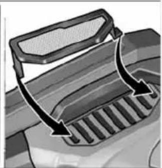
natural_image
Diagram of a vehicle's intake manifold with arrows indicating direction (no text or symbols)Peter Lameli Technical Head
Klaus Peter Weinper Head of Quality Department (QD)
natural_image
Illustration of a hand using a tire to lift a car wheel, with directional arrows indicating motion (no text or symbols)natural_image
Illustration of a person using a robotic arm to lift a rope on a metal railing (no text or symbols)natural_image
Mechanical assembly diagram showing a mechanical component with three circular parts and a central shaft (no text or symbols)Rullide vahetamine

Veorull:
natural_image
Mechanical assembly diagram showing a cutting tool with a magnified inset view of its work (no text or symbols present)natural_image
Illustration of a hand using a tool to adjust or install a mechanical component, with no visible text or symbols.natural_image
Illustration of a hand using a tool to adjust or install a mechanical component, with arrows indicating motion (no text or symbols present)natural_image
Close-up of a mechanical component with an arrow indicating direction (no text or symbols visible)natural_image
Close-up of a mechanical component with a black arrow indicating a process step, no visible text or symbolsnatural_image
Close-up of a microwave oven with control panel and buttons (no visible text or symbols)natural_image
Two-panel illustration showing a car's front and side views of a gridded door, with arrows indicating direction of movement (no text or symbols)
Peter Lameli
Technical Head

Klaus Peter Weinper Head of Quality Department (QD)
15.12.2020
natural_image
Illustration of a hand using a tool to cut a tire on a textured surface, with directional arrows indicating motion (no text or symbols)natural_image
Illustration of a robotic arm gripping a metal railing (no text or symbols)natural_image
Mechanical assembly diagram showing a clamping mechanism with three components (no text or labels)Ritinėlių keitimas

Varantysis ritinélis:
natural_image
Mechanical assembly diagram showing a cutting tool with a workpiece and a close-up inset of the component (no text or symbols visible)natural_image
Illustration of a hand using a tool to adjust or install a mechanical component, with no visible text or symbols.natural_image
Illustration of a hand using a tool to adjust a mechanical component with arrows indicating motion (no text or symbols present)natural_image
Close-up of a mechanical component with an arrow indicating a process or operation, no visible text or symbols.natural_image
Close-up of a mechanical component with an arrow pointing to a button (no text or symbols visible)natural_image
Close-up of a microwave oven with control panel and buttons, showing a close-up of the lid (no text or symbols visible)natural_image
Two-panel illustration showing a car's side profile of the front and rear compartments, with arrows indicating movement or force direction (no text or symbols)Peter Lameli Technical Head
Klaus Peter Weinper Head of Quality Department (QD)
15.12.2020
natural_image
Illustration of a hand using a tool to lift a tire on a textured surface, with directional arrows indicating motion (no text or symbols)natural_image
Illustration of a person using a device on a metal ladder (no text or symbols)natural_image
Mechanical assembly diagram showing a pin roller being inserted into a housing (no text or symbols)Rullīšu nomaiņa

Piedziñas rullitis:
■ Iznemiet akumulatoru.
■ Roktura demontāža (1.).
■ Atvāziet malā korpusa apvalku (2.).

natural_image
Mechanical assembly diagram showing a cutting tool and a workpiece with a cylindrical component, no visible text or symbols.natural_image
Illustration of a hand using a tool to adjust or install a mechanical component, with no visible text or symbols.natural_image
Illustration of a hand using a tool to adjust a mechanical component with arrows indicating motion (no text or symbols present)natural_image
Close-up of a mechanical component with an arrow indicating a process or operation, no visible text or symbols.natural_image
Close-up of a mechanical component with a black arrow pointing to a button, no visible text or symbolsnatural_image
Close-up of a microwave oven with control panel and buttons, showing a close-up of the button (no text or symbols visible)natural_image
Close-up of a car's front bumper with a curved arrow indicating motion (no text or symbols)
natural_image
Diagram of a vehicle's exhaust griddling with airflow arrows indicating movement (no text or symbols)■ Puteklu filtru noņemiet un izpūtiet ar sausu saspiesto gaisu.
Oğlsukas
Peter Lameli Technical Head
Klaus Peter Weinper Head of Quality Department (QD)
15.12.2020
natural_image
Two-panel illustration showing car door frame and side profile of a gridded cover (no text or symbols)natural_image
Close-up of a microwave oven with a black button and control panel (no visible text or symbols)natural_image
Close-up of a mechanical component with a black arrow pointing to a section, no visible text or symbolsnatural_image
Close-up of a computer mouse control panel with an arrow pointing to the handle (no text or symbols visible)natural_image
Illustration of a hand using a tool to adjust or install a mechanical component, with no visible text or symbols.natural_image
Illustration of a hand using a tool to adjust or install a mechanical component, with arrows indicating motion (no text or symbols present)natural_image
Mechanical tool diagram showing a cutting machine with a cylindrical component inserted, alongside an inset view of the machining process (no text or symbols present)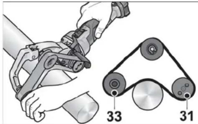
natural_image
Mechanical assembly diagram showing a mechanical component with three parts and a central shaft (no text or symbols)natural_image
Illustration of a person using a robotic arm on a metal platform (no text or symbols)natural_image
Close-up of hands using a power tool to cut a mechanical component on a textured surface, with no visible text or symbols.BF 140 الم parties shrimpي