USER MANUAL CoolAir RT 780 DOMETIC
natural_image
3D rendering of a white plastic enclosure or hood with curved and rectangular panels (no text or symbols visible)
RT780
EN
Assembly kit for Iveco Stralis AS/AS ^3 and AT (High roof)
Installation Manual 8
DE
Montagesatz für Iveco Stralis AS/AS ^3 und AT (Hochdach)
Montageanleitung 24
FR
Kit de montage pour Iveco Stralis AS/AS³ et AT (Toit élevé)
Instructions de montage....41
ES
Juego de montaje para Iveco Stralis AS/AS ^3 y AT (Techo alto)
Instrucciones de montaje 58
PT
Kit de montagem para Iveco Stralis AS/AS ^3 e AT (teto alto)
Instruções de montagem 75
IT
Set di montaggio per Iveco Stralis AS/AS ^3 e AT (Tetto alto)
Indicazioni di montaggio 92
NL
Montageset voor Iveco Stralis AS/AS³ en AT (Hoogdak)
Montagehandleiding 109
DA
Monteringssæt til Iveco Stralis AS/AS ^3 og AT (Højt tag)
Monteringsvejledning 126
SV
Monteringssats för Iveco Stralis AS/AS ^3 och AT (Högtak)
Monteringsanvisning 142
NO
4
natural_image
3D diagram of a rectangular mechanical component with an arrow indicating direction (no text or symbols)
7
8
| bl br gl gr ro sw w | | | | | |
| EN | Blue Brown Yellow | Green Red Black White | | | | |
| DE | Blau Braun Gelb Grün | Rot Schwarz | Weiß | | | | |
| FR | Bleu | Marron | Jaune | Vert | Rouge | Noir | Blanc |
| ES | Azul | Marrón | Amarillo | Verde | Rojo | Negro | Blanco |
| PT | Azul | Castanho | Amarelo | Verde | Cinzento | Vermelho | Preto |
| IT | Blu | Marrone | Giallo | Verde | Rosso | Nero | Bianco |
| NL | Blauw | Bruin | Geel | Groen | Rood | Zwart | Wit |
| DA | Blå | Brun | Gul | Grøn | Rød | Sort | Hvid |
| SV | Blå | Brun | Gul | Grön | Röd | Svart | Vit |
| NO | Blå | Brun | Gul | Grønn | Rød | Svart | Hvit |
| FI | Sininen | Ruskea | Keltainen | Vihreå | Punainen | Musta | Valkoinen |
| RU | Синий | Коричневый | Желтый | Зепеный | Красный | Черный | Белый |
| PL | Niebieski | Brązowy | Żółty | Zielony | Czerwony | Czamy | Biały |
| SK | Modrá | Hnedá | Żltá | Zelená | Červená | Čierna | Biela |
| CS | Modrá | Hnèda | Żlutá | Zelená | Červená | Černá | Bílá |
| HU | Kék | Barna | Sárga | Zöld | Piros | Fekete | Fehér |
Contents
1 Symbols and formats ....9
2 Safety instructions ....9
2.1 Using the device ..... 10
2.1 Using the device ..... 10
2.2 Handling electrical cables....10
3 Conventions in this manual .... 11
3.1 General information on the installation manual 11
3.2 Target group 11
4 Intended use .... 11
5 Scope of delivery....12
6 Accessories ....12
7 Installation....13
7.1 Notes on installation ..... 13
7.2 Removing the sunroof....15
7.3 Preparing unit fastening (Iveco Stralis AS ^3 only) .....15
7.4 Preparing the unit .....15
7.5 Attaching the seal for the cab roof ..... 16
7.6 Installing the unit in the sunroof 16
7.7 Installing the electrical supply lines....17
7.8 Fastening the cover frame....18
8 Configuration of unit software 18
8.1 Starting and ending configuration mode ..... 19
8.2 Menu level 1: Set temperature .....19
8.3 Menu level 2: Low voltage cut-off.... 20
8.4 Menu level 3: Operating mode .....21
8.5 Menu level 4: Default setting 22
8.6 Menu level 5: Temperature unit display 22
9 Technical data 23

WARNING!
Safety instruction: Failure to observe this instruction can cause fatal or serious injury.

CAUTION!
Safety instruction: Failure to observe this instruction can lead to injury.

NOTICE!
Failure to observe this instruction can cause material damage and impair the function of the product.

NOTE
Supplementary information for operating the product.
2 Safety instructions
You must read the entire manual thoroughly and carefully.
We can only guarantee the reliability of the air conditioning roof unit if the instructions are adhered to. The same applies to the prevention of injury and damage to property.
The manufacturer accepts no liability for damage in the following cases:
• Faulty assembly or connection
- Damage to the product resulting from mechanical influences and excess voltage
• Alterations to the product without express permission from the manufacturer
- Use for purposes other than those described in the operating manual
2.1 Using the device
- The freedom of movement of semi-trailers (of the outer edges of the semi-trailer when turning or jackknifing) and other vehicle attachments must not be restricted.
- Only use the air conditioning roof unit for the purpose specified by the manufacturer and do not make any alterations or structural changes to the device.
- Do not use the air conditioning roof unit if it is visibly damaged.
- The air conditioning roof unit must be installed safely so that it cannot tip over or fall down.
• Installation, maintenance and repair work may only be carried out by qualified personnel from a specialist company who are familiar with the risks involved and the relevant regulations.
- Do not use the air conditioning roof unit near flammable fluids and gases.
- Do not operate the air conditioning roof unit if the ambient temperature is below 0^ .
- Do not undo the upper cover of the air conditioning roof unit in the event of a fire. Use approved extinguishing agents instead. Do not use water to extinguish fires.
- Please inform your vehicle manufacturer if the height entered in your vehicle documents needs to be altered due to the installation of the air conditioning roof unit.
– Iveco Stralis AS/AT height: 166 mm.
– Iveco Stralis AS ^3 height: 188 mm
- Disconnect all power supply lines when working on the air conditioning roof unit (cleaning, maintenance, etc).
2.2 Handling electrical cables
- Use cable ducts to lay cables through walls with sharp edges.
- Do not lay loose or bent cables next to electrically conductive materials (metal).
- Do not pull on the cables.
- Attach and lay the cables in such a manner that they cannot be tripped over or damaged.
- The electrical power supply may only be connected by a specialist workshop.
- Fit a fuse of 25 amps to the connection to the vehicle's power supply.
- Never lay power supply lines (battery leads) in the vicinity of signal or control cables.
3 Conventions in this manual
This installation manual contains the essential information and instructions for installing the air conditioning roof unit. The information contained is orientated towards the company installing the air conditioning roof unit.
The following instructions are intended to help you properly use the installation manual:
- The installation manual is part of the scope of delivery and should be stored carefully.
- The installation manual provides you with important information on the installation of the device and can also be used as a reference material in the event of repairs.
- The manufacturer assumes no liability for non-observance of this installation manual. Any claims are excluded in this case.
3.2 Target group
The installation and configuration information in this manual is intended for qualified installation personnel who are familiar with the guidelines and safety precautions to be applied during the installation of lorry accessory parts.
4 Intended use
The installation kit (AS/AT: ref. no. 9100300104, AS ^3 : ref. no. 9100300105) enables the installation of an air conditioning roof unit CoolAir RT780 (ref. no. 9105305547) in a roof ventilation opening (hatch) provided at the plant in a Iveco Stralis AS/AT (high roof) or Iveco Stralis AS ^3 (high roof) driver cab.

NOTICE!
- The RT780 unit is not suitable for installation in construction machines, agricultural machines or similar equipment. They will not work properly if exposed to strong vibrations.
- Operating the RT780 unit with voltages other than those specified can result in damage to the devices.

NOTE
The RT780 unit is only designed for ambient temperatures of up to 43 °C.
5 Scope of delivery
CoolAir RT780 installation kit for Iveco Stralis AS/AT, ref. no. 9100300104
Part designation Quantity Ref. no.
| Installation manual 1 4445102177 |
| Cover frame 1 4443000260 |
| 2.5 m insulating tape (profile: 10 x 20 mm) 1 – |
| Spacer sleeve L = 18 mm, ∅ 14 mm | 12 | 4443900236 |
| Hex screw M8 x 45 12 – |
| Washer 8.4 x 20 12 – |
| Spring washer M8 12 – |
| Connection cable 6 mm2 x 4 m | 1 | 4441300149 |
| Cable binder | 1 – | |
CoolAir RT780 installation kit for Iveco Stralis AS ^3 , ref. no. 9100300105
Part designation Quantity Ref. no.
| Installation manual 1 4445102177 |
| Cover frame 1 4443000260 |
| 2.5 m insulating tape (profile: 35 x 20 mm) | 1 – |
| Spacer sleeve L = 40 mm | 12 4443900237 |
| Hex screw M8 x 65 12 – | |
| Washer 8.4 x 20 12 – | |
| Spring washer M8 12 – | |
| Connection cable 8 mm ^2 x 9.5 m | 1 4441300097 |
| Cable binder | 1 – |
6 Accessories
Available as accessories (not included in the scope of delivery):
Part designation Ref. no.
| Connection cable 8 mm ^2 x 11 m | 9100300027 |
7 Installation

NOTICE!
- The air conditioning roof unit may only be installed by qualified personnel from a specialist company. The following information is intended for technicians who are familiar with the guidelines and safety precautions to be applied.
- The manufacturer only assumes liability for parts included in the scope of delivery. The validity of the warranty expires if the device is installed together with third-party parts.
- Check whether the roof of the vehicle is able to support the weight of a person before climbing onto it. Ask the vehicle manufacturer about the permitted roof loads.
7.1 Notes on installation
These installation instructions must be read completely prior to the installation of the air conditioning roof unit.
The following tips and instructions must be observed while installing the air conditioning roof unit:

WARNING!
Make sure that all electrical components are electrically discharged before carrying out work on them!
- Always check whether any vehicle components could be damaged or their operation impaired by the unit before installing the air conditioning roof unit. You can use fig. 1, page 3 and fig. 2, page 3 to check the dimensions of the installed unit. The dotted line indicates the middle of the sunroof opening.
- Before installation, find out (by consulting the manufacturer of the vehicle) whether the construction is designed for the static weight and the loads of the parking cooler when the vehicle is in motion. The manufacturer of the air conditioning roof unit assumes no liability whatsoever.
- The roof inclination of the mounting surface may not exceed 20^ in the direction of travel.
- The supplied assembly parts must not be modified during installation.
- The ventilation slots (grill) may not be covered (minimum distance from other attachment parts: 10 cm).
-
You can connect the unit to the battery via the lorry's terminal block or directly. The terminal block is to be preferred for the connection. On some vehicles, larger consumers connected to the terminal block are switched off after a short while if the power requirement is too high. Ask your vehicle manufacturer for the specifications of the terminal block.
-
When installing the system and making the electrical connections, observe the guidelines from the body manufacturer.
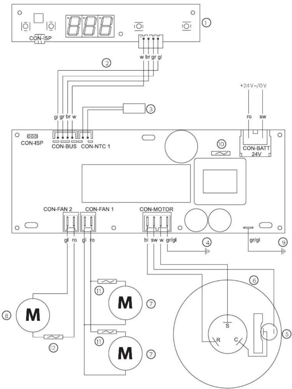
- Pay attention to the connection plan for the device:
| No. in fig. 8, page 6 | Designation |
| 1 | C | o | n | t | r | o |
| 2 Connection cable |
| 3 Room temperature sensor |
| 4 | E | a | r | t | h | |
| 5 Klickson (compressor) |
| 6 | C | o | m | p | r | e |
| 7 | C | o | n | d | e | n |
| 8 | V | a | p | o | r | i |
| 9 | E | a | r | t | h | |
| 10 25 A fuse |
| 11 2 A fuse |
| 12 4 A fuse |

WARNING!
Before installing the air conditioning roof unit, all connections to the battery of the vehicle must be disconnected.
Non-observance of this regulation can result in danger of electrocution.

CAUTION!
Improper installation of the air conditioning roof unit can result in irreparable damage to the device and put the safety of the user at risk.
The manufacturer will not be held liable for claims if the air conditioning roof unit is not installed according to this installation manual. That applies to malfunctions and the safety of the air conditioning roof unit, in particular to injuries and damage to property.

NOTE
After installing the unit, the specified parameters of the unit software must be checked (chapter "Configuration of unit software" on page 18).
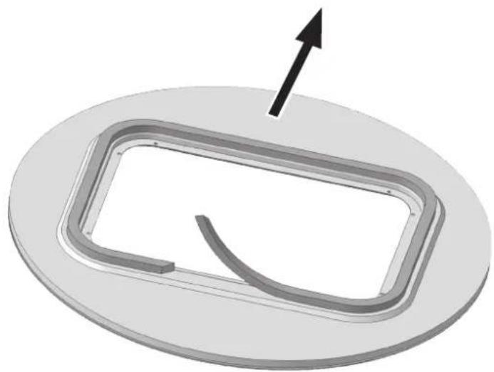
7.2 Removing the sunroof
▶Remove all screws and fixtures of the existing sunroof.
▶Take out the sunroof.
Remove the sealant around the opening, so that the surface is clean and free of grease.

NOTE
Dispose of all waste material, glue, silicone and seals separately. Observe the local disposal guidelines.
7.3 Preparing unit fastening (Iveco Stralis AS ^4 only)
▶ Enlarge the 12 existing ∅ 6.5 mm holes for fastening the sunroof to a diameter of 8.5 mm.
7.4 Preparing the unit

NOTICE!
During preparatory work on the surfaces, secure the unit from falling down. Make sure that the work surface is clean and level to ensure that the unit is not damaged.
▶ Place the air conditioning roof unit on a work surface with the housing facing down.

NOTICE!
Screw in the thread insert vertically.
Do not exceed the screw torque of 10 Nm.
▶Screw in the 12 self-threading M8 thread inserts in the blind holes marked with "1" and "4" (fig. 3, page 4).
Use the supplied 1/4" bit for this.
7.5 Attaching the seal for the cab roof

NOTICE!
Ensure that the adhesive surface for the seal between the unit and the cab roof is clean (free of dust, oil, etc.).
▶ Stick the 2.5 m insulating tape to the cab roof, following the outline of the sunroof (fig. 4, page 4):
- RT780 Iveco Stralis AS/AT: insulating tape 10 x 20 mm
- RT780 Iveco Stralis AS ^3 : insulating tape 35 x 20 mm
▶Provide the abutting edge and the top edge of the insulating tape with an unhardened plastic butyl sealing compound (e.g. SikaLastomer-710).
7.6 Installing the unit in the sunroof
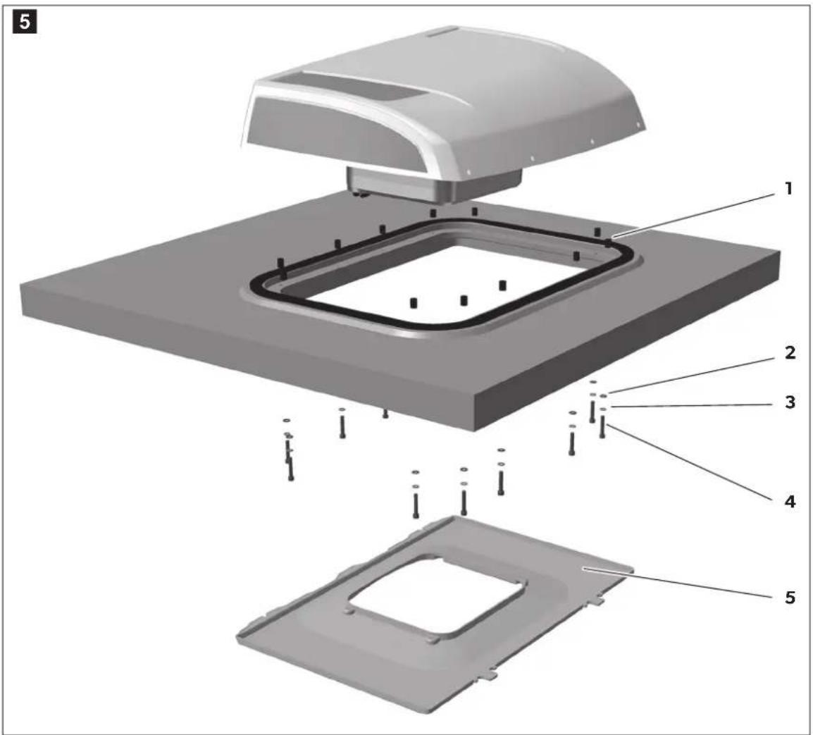
▶ Set the unit down centrally aligned and in the direction of travel (fig. 1, page 3) on the sunroof opening.

NOTE
Make sure the air conditioning roof unit is centred perfectly. The seal must be applied continuously around the air conditioning roof unit after being placed on the roof of the vehicle. This is the only way to ensure a tight seal.
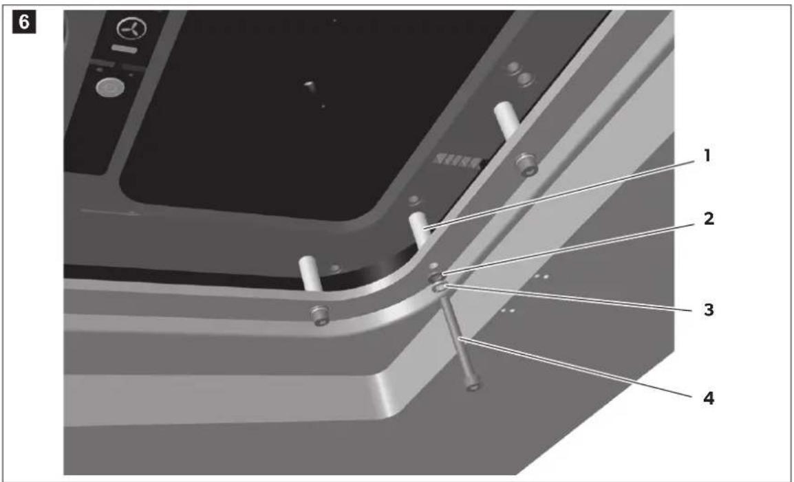
▶ Position the spacer sleeve (fig. 6 1, page 5) on the fixing drill holes as shown in fig. 6, page 5.
- RT780 Iveco Stralis AS/AT: spacer sleeve L = 18 mm
- RT780 Iveco Stralis AS ^3 : spacer sleeve L= 40 mm
Screw one hex screw (fig. 6 4, page 5) with washer (fig. 6 2, page 5) and spring washer (fig. 6 3, page 5) into each of the 12 thread inserts on the underside of the unit.
- RT780 Iveco Stralis AS/AT: hex screw M8 x 45 mm
- RT780 Iveco Stralis AS ^3 : hex screw M8 x 65 mm

NOTICE!
Do not exceed the specified torque under any circumstances. This is the only way to ensure that the thread inserts are not torn out.
▶ Tighten the screws with a torque of 8 Nm.
7.7 Installing the electrical supply lines

WARNING!
- The electrical power supply may only be performed by qualified personnel with specialist knowledge.
- Make sure there is no voltage present on electrically operated components before carrying out work on them!

NOTICE!
- Fit a fuse of 25 amps to the connection to the vehicle's power supply.
- The battery must be able to supply the required current and voltage (chapter "Technical data" on page 23).

NOTE
The unit is equipped as standard with:
- Iveco Stralis AS/AT: a 4 m long cable with a cross-section of 6mm^2
- Iveco Stralis AS ^3 : a 9.5 m long cable with a cross-section of 8 mm ^2
If longer cable lengths are required, then the cable cross-section must be increased by an authorised specialist workshop:
In this case cut off the cable as closely as possible to the unit (max. 0.5 m) and then establish a suitable connection with a larger cable cross-section.
The manufacturer recommends:
- Iveco Stralis AS/AT: when the cable is extended by 4 m to 6 m in length, use a cross-section of at least 8 mm ^2 .
- Iveco Stralis AS/AT: when the cable is extended by 9 m to 11 m in length, use a cross-section of at least 10 mm ^2 .
Iveco Stralis AS/AT: You can connect the unit to the battery via the lorry's terminal block or directly. The terminal block is to be preferred for the connection. Ask your vehicle manufacturer for the specifications of the terminal block.
Iveco Stralis AS ^3 : You can connect the unit to the battery via the lorry's terminal block or directly. Here, the connection directly to the battery should be preferred, as the consumer which is connected to the terminal block switches off after approx. 10 min if there is a high power requirement.
▶Lay the supply line and connect it to the vehicle (red line to plus, black line to minus).
▶Plug in the supply line plug into the socket of the air conditioning roof unit supply line.
To relieve strain on the supply line, secure it with a cable tie, e.g. to the cab roof.
7.8 Fastening the cover frame

NOTICE!
Screw the screws in carefully order not to damage the cover frame.
▶ Fasten the cover frame (fig. 5 5, page 5) the same way as for the original frame for the sliding roof.
8 Configuration of unit software
Before you first start up the unit, the controls can be adapted to suit the installation conditions. This must be done by the person installing the unit.
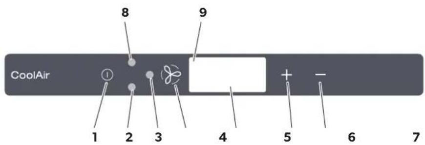
In configuration mode, the following unit software parameters must be set at the control panel (fig. 7, page 6).
| Menu level | Parameter Meaning | Default setting |
| 1 Set temperature | The unit starts at the temperature defined here. | 20 °C (68 °F) |
| 2 cut-off | L o w | The battery monitor shuts down the unit at the voltage defined here. | Characteristic figure 4 = 22,8 V |
| 3 Operating mode | The unit starts with the operating mode defined here. | 0 = Automatic mode |
| 4 Default settings | Parameters 1 – 3 can be reset to the default settings. | -- |
| 5 display | T e m | The temperature can be displayed in °C or °F. | e°C u n |

NOTE
Configuration mode can still be activated if the undervoltage protection mechanism has switched off the unit and only residual voltage is available.
8.1 Starting and ending configuration mode
The adjustable parameters can be changed in configuration mode:
When using the ① button to switch on the unit, hold both buttons + and - pressed until the compressor LED flashes.
√You are now in configuration mode.
√ The display version (e. g. "3.1S") appears in the display for 2 seconds.
√The first digit of the display shows the menu level and the second and third digits show the parameters which can be set, e.g. 1.17 for menu level 1 and a set target value of 17 °C.

NOTE
If you make no entry on the control panel for 60 seconds, the unit quits configuration mode and shuts down.
▶Press the button to quit configuration mode.
The unit always starts with a defined value for the room temperature. This parameter can be configured between 17 and 30 °C (62 and 86 °F).
▶ Start configuration mode (chapter "Starting and ending configuration mode" on page 19).
√The first digit of the display shows the menu level and the second and third show the parameter which can be set.
▶Press the button to change the parameters.
▶ Use the + and - buttons to select the target value (in °C) at which the unit should start operation.
√The digits in the display flash until the parameter you entered is confirmed.
▶Press the button to confirm your entry.
√The set value is saved and is then used when the unit is restarted.
√You are now in menu level 1 again and can use the + and - buttons to switch between menu levels.
The battery monitor protects the battery from excessive discharging.

NOTICE!
When the battery monitor switches the device off, the battery only has part of its charging capacity. Avoid starting repeatedly or operating electrical consumers. Make sure that the battery is recharged. As soon as the required voltage is available again, the unit can be operated again.
If only the set power supply is available here for the air conditioning roof unit, the unit is switched off.
▶ Start configuration mode (chapter "Starting and ending configuration mode" on page 19).
√The first digit of the display shows the menu level and the second and third show the parameter which can be set.
▶Press the + button once to switch to menu level 2.
▶Press the button to change the parameter.
√The digits in the display flash until the parameter you entered is confirmed.
▶Use the + and - buttons to set the value for low voltage shutdown. The characteristic figures at second and third place on the display represent the voltage (V) at which the unit is shut down:
| Characteristic figure | Low voltage shutdown |
| 122.2 623.0 | |
| 222.4 723.1 | |
| 322.6 823.2 | |
| 422.8 923.4 | |
| 522.9 1023.6 | |
| Characteristic figure | Low voltage shutdown |
| |
| |
| |
| |
| |
▶Press the button to confirm your entry.
√The set value is saved and is then used when the unit is restarted.
√You are now in menu level 2 again and can use the + and - buttons to switch between menu levels.
The unit always starts with a defined operating mode for room temperature. This parameter can be configured:
▶ Start configuration mode (chapter "Starting and ending configuration mode" on page 19).
√The first digit of the display shows the menu level and the second and third show the parameter which can be set.
▶Press the + button twice to switch to menu level 3.
▶Press the button to change the parameters.
√The digits in the display flash until the parameter you entered is confirmed.
▶ Use the + and - buttons to set the mode with which the unit starts up:
| Characteristic figure | Operating mode |
| Automatic mode | |
| Operating mode 1 | |
| Operating mode 2 | |
| Operating mode 3 | |
▶Press the button to confirm your entry.
√The set value is saved and is then used when the unit is restarted.
√You are now in menu level 3 again and can use the + and - buttons to switch between menu levels.
You can reset the parameters you set in configuration mode on menu levels 1 to 3 to the default settings:
▶ Start configuration mode (chapter "Starting and ending configuration mode" on page 19).
√The first digit of the display shows the menu level and the second and third show the parameter which can be set.
▶Press the + button three times to switch to menu level 4.
√The display shows --.
▶Press the button, to reset the unit to the factory settings.
√ --flashes in the display.
▶Press the + button.
√The display shows 00.
▶Press the button to confirm your entry.
√The parameters set in configuration mode are reset to the default setting.
√ You are now in menu level 4 and can use the + and - buttons to switch between menu levels.
The system can display the room temperature in ^ C or ^ F. This parameter can be configured:
▶ Start configuration mode (chapter "Starting and ending configuration mode" on page 19).
√The first digit of the display shows the menu level and the second and third show the parameter which can be set.
▶Press the + four times to switch to menu level 5.
▶Press the button to change the parameters.
√The digits in the display flash until the parameter you entered is confirmed.
▶ Use the + and - buttons to select the temperature unit that the system should display.
▶Press the button to confirm your entry.
√The set value is saved and is then used when the unit is restarted.
√You are now in menu level 5 again and can use the + and - buttons to switch between menu levels.
9 Technical data
| Air conditioning roof unit CoolAir RT780 |
| Ref. number: 9105306291 | |
| Cooling capacity: 820 W | |
| Rated input voltage: 24 V--- | |
| Input voltage range: | 22.5 V--- - 30 V--- |
| Max. current consumption: 22 A | |
| Low voltage shutdown: Configurable (chapter “Menu level 2: Low voltage cut-off” on page 20) |
| Dimensions (L x B x H): | 635 x 830 x 288 mm |
| Weight: approx. 21 kg | |
Inhaltsverzeichnis
7 Installation....29
7 Installation....46
7 Installation....147
7.1 Information om installationen ....147
7.2 Demontera tackluckan....149
dometic.com/sales-offices