USER MANUAL PVKO 50 B2 PARKSIDE
natural_image
Exterior view of a cylindrical industrial vacuum cleaner with cooling fans and wheels (no visible text or symbols)

text_image
PDF ONLINE
www.1idl-service.com
VERTICAL COMPRESSOR 50L - PVKO 50 B2 VERTIKALER KOMPRESSOR 50L - PVKO 50 B2 COMPRESSEUR VERTICAL 50 L - PVKO 50 B2

VERTICAL COMPRESSOR 50L
Operating and Safety Instructions
Translation of Original Operating Manual

COMPRESSEUR VERTICAL 50 L
Before reading, unfold the page containing the illustrations and familiarise yourself with all functions of the device.
DE AT CH
GB / IE Operating and Safety Instructions Page 01
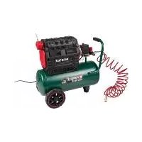
text_image
Technical diagram of two cylindrical industrial machines with numbered components and labeled parts
2
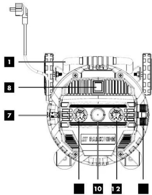
text_image
1
8
7
10 1 2
3
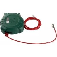
natural_image
Technical line drawing of a cylindrical industrial vessel with mounting feet and a rotary knob, labeled with number 5 (no text or symbols on the diagram itself)
text_image
4
D
6
C
A
D
6
C
A
text_image
5
124
text_image
6
7
7.3
7.1 7.2
7
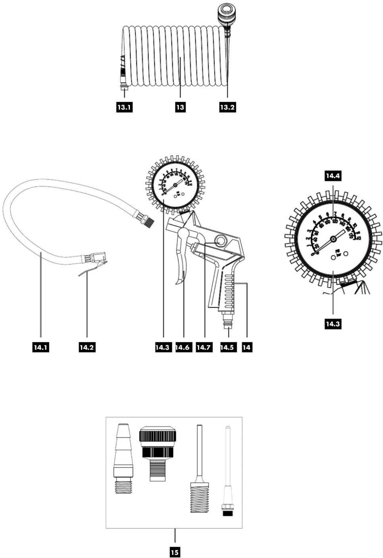
Table of contents: Page:
- Explanation of the symbols on the device....2
- Introduction....3
- Device description (Fig. 1 -7) ....3
- Scope of delivery 3
- Proper use....3
- General power tool safety warnings....4
- Technical data....6
- Unpacking....7
- Before commissioning....7
- Assembly and operation....7
- Using the accessories (included in the scope of delivery) (Fig. 7)....8
- Electrical connection....9
- Cleaning, maintenance, storage and ordering spare parts....9
- Disposal and recycling 10
- Troubleshooting....11
- Warranty certificate....12
- Exploded view....114
- Declaration of conformity....116
1. Explanation of the symbols on the device

GB IE
Warning - Read the operating manual to reduce the risk of injury.

GB IE
Wear hearing protection. Excessive noise can result in a loss of hearing.
GB IE
Warning - Hot surfaces!
GB IE
Warning against electrical voltage

GB IE
Warning! Compressor can start up without warning.
GB IE
Do not expose the machine to rain. The device may only be stationed, stored and operated in dry ambient conditions.

GB IE
Specification of the sound power level in dB
⚠ Attention!
GB IE
We have marked points in this operating manual that impact your safety with this symbol.
2. Introduction
Manufacturer:
scheppach
Günzburger Straße 69
D-89335 Ichenhausen
Dear Customer
We hope your new tool brings you much enjoyment and success.
Note:
In accordance with the applicable product liability laws, the manufacturer of this device assumes no liability for damage to the device or caused by the device arising from:
- Improper handling
- Failure to comply with the operating manual,
• Repairs carried out by third parties, unauthorised specialists
• Installing and replacing non-original spare parts,
- Improper use
- Failures of the electrical system in the event of the electrical regulations and VDE provisions 0100, DIN 57113 / VDE 0113 not being observed
Note:
Read the whole text of the operating manual before assembly and commissioning.
This operating manual should help you to familiarise yourself with your device and to use it for its intended purpose.
The operating manual includes important instructions for safe, proper and economic operation of the device, for avoiding danger, for minimising repair costs and downtimes, and for increasing the reliability and extending the service life of the device.
In addition to the safety instructions in this operating manual, you must also observe the regulations applicable to the operation of the device in your country.
Keep the operating manual at the device, in a plastic sleeve, protected from dirt and moisture. They must be read and carefully observed by all operating personnel before starting the work.
The device may only be used by personnel who have been trained to use it and who have been instructed with respect to the associated hazards.
The required minimum age must be observed.
In addition to the safety instructions in this operating manual and the separate regulations of your country, the generally recognised technical rules relating to the operation of such machines must also be observed.
We accept no liability for accidents or damage that occur due to a failure to observe this manual and the safety instructions
3. Device description (Fig. 1 - 7)
- Transport handle
- Quick-coupling (regulated compressed air)
- Pressure vessel
- Wheel
- Drain screw for condensate
- Foot
- Safety valve
7.1. Drain nut
7.2. Safety connection
7.3. Cap
- On/off switch
- Manometer (regulated pressure)
- Pressure regulator
- Manometer (container pressure)
- Wheel bolt
- Spiral hose, 5 m
13.1 Connection
13.2 Quick-coupling (Spiral hose)
- Compressed air tyre inflation meter
14.1 Inflation hose
14.2 Valve plug connection
14.3 pressure gauge
14.4 Scale
14.5 Connection
14.6 Trigger lever
- Adapter set
A. Hexagonal bolt
B. Nut
C. Washer
D. Flange nut
4. Scope of delivery
- Compressor
- 2x wheels (4)
- 2x feet (6)
- Assembly material
- Operating manual
- Spiral hose, 5 m (13)
- Compressed air tyre inflation meter (14)
- Adapter set (15)
5. Proper use
The compressor is used to generate compressed air for pneumatically powered tools that can be operated with an air rate of up to 140 l/min. (e.g. tyre inflaters, air blow guns, paint spray guns). Due to the limited air flow rate, it is not possible to operate tools with a very high compressed air consumption (e.g. orbital sanders, straight grinders and impact screwdriver).
The machine may only be used in the intended manner. Any use beyond this is improper. The user/operator, not the manufacturer, is responsible for damages or injuries of any type resulting from this.
The device may only be operated by persons who are aged 16 and above. An exception to this is use by minors if the use takes place as part of occupational training in order to gain proficiency under the supervision of an instructor.
Please note that our equipment was not designed with the intention of use for commercial or industrial purposes. We assume no guarantee if the device is used in commercial or industrial applications, or for equivalent work.
Failure to follow all instructions listed below may result in electric shock, fire and/or serious injury.
Save all warnings and instructions for future reference.
The term "power tool" in the warnings refers to your mains-operated (corded) power tool or battery-operated (cordless) power tool.
Work area safety
a. Keep your work area clean and well-lit. Cluttered or dark areas invite accidents.
b. Do not operate electric tools in explosive atmospheres, such as in the presence of flammable liquids, gases or dust. Electric tools produce sparks that may ignite dust or vapours.
c. Keep children and other people away while using the electric tool. You may lose control of the power tool if distracted.
Electrical safety
a. Power tool plugs must match the outlet. Never modify the plug in any way. Do not use any adapter plugs with earthed (grounded) power tools. Unmodified plugs and matching outlets will reduce risk of electric shock.
b. Avoid body contact with earthed surfaces, such as pipes, heaters, ovens and refrigerators. There is an increased risk of electric shock if your body is earthed or grounded.
c. Do not expose power tools to rain or wet conditions. Water entering a power tool will increase the risk of electric shock.
d. Do not abuse the cord. Never use the cord for carrying, pulling or unplugging the power tool. Keep cord away from heat, oil, sharp edges or moving parts. Damaged or entangled cords increase the risk of electric shock.
e. If you work with an electric tool outdoors, only use extension cables that are also suitable for outdoor use. Using an extension cable suitable for outdoor use reduces the risk of an electric shock. Only use approved and appropriately identified extension cables for use outdoors. Only use cable reels in the unrolled state.
f. If operating a power tool in a damp location is unavoidable, use a residual current circuit breaker with a trigger current of 30 mA or less to protect the power supply. Using a fault-current circuit breaker reduces the risk of an electric shock.
Personal safety
a. Stay alert, watch what you are doing and use common sense when operating a power tool. Do not use a power tool while you are tired or under the influence of drugs, alcohol or medication. A moment of carelessness when using electrical tools can result in serious injuries.
b. Use personal protective equipment. Always wear eye protection. Wearing personal protective equipment, such as dust masks, anti-slip safety shoes, safety helmet or hearing protection, depending on the type and use of the electric tool, reduces the risk of injuries.
c. Prevent unintentional starting. Ensure the switch is in the off-position before connecting to power source and/or battery pack, picking up or carrying the tool. Carrying electric tools with your finger on the switch or connecting electric tools to the power supply when they are already switched on invites accidents.
d. Remove any adjusting key or wrench before turning the power tool on. A wrench or a key left attached to a rotating part of the power tool may result in personal injury.
e. Do not overreach. Keep proper footing and balance at all times. This enables better control of the power tool in unexpected situations.
f. Dress properly. Do not wear loose clothing or jewellery. Keep hair, clothing and gloves away from moving parts. Loose clothes, jewellery or long hair can be caught in moving parts. When working outdoors, rubber gloves and anti-slip footwear is recommended. Tie long hair back in a hair net.
g. If dust extraction and collection devices can be mounted, make sure that they are connected and used properly. Use of dust collection can reduce dust-related hazards.
h. Do not let familiarity gained from frequent use of tools allow you to become complacent and ignore tool safety principles. A careless action can cause severe injury within a fraction of a second.
a. Do not force the power tool. Use the correct power tool for your application. The correct power tool will do the job better and safer at the rate for which it was designed.
b. Do not use the power tool if the switch does not turn it on and off. Any power tool that cannot be controlled with the switch is dangerous and must be repaired.
c. Disconnect the plug from the power source and/or remove the battery pack, if detachable, from the power tool before making any adjustments, changing accessories, or storing power tools. These precautionary measures will prevent the electric tool from starting unintentionally.
d. Store idle power tools out of the reach of children and do not allow persons unfamiliar with the power tool or these instructions to operate the power tool. Power tools are dangerous in the hands of untrained users. Unused electric tools should be stored in a dry, elevated or closed location out of the reach of children.
e. Maintain power tools and accessories. Check whether moving parts function properly and do not get stuck and whether parts are broken or are damaged and thus adversely affect the electric tool function. If damaged, have the power tool repaired before use. Many accidents are caused by poorly maintained power tools.
f. Keep cutting tools sharp and clean. Properly maintained cutting tools with sharp cutting edges are less likely to bind and are easier to control.
g. Use the power tool, accessories and tool bits etc. in accordance with these instructions, taking into account the working conditions and the work to be performed. Use of the power tool for operations different from those intended could result in a hazardous situation.
h. Keep handles and grasping surfaces dry, clean and free from oil and grease. Slippery handles and grasping surfaces do not allow for safe handling and control of the tool in unexpected situations.
Service
a. Only have your electric tool repaired by qualified specialists and only with original spare parts. This ensures that safety of the electric tool is maintained.
Safety instructions for compressors
Attention!
The following basic safety measures must be observed when using this compressor for protection against electric shock, and the risk of injury and fire.
Read and observe these instructions before using the device.
Safe work.
-
Take care of your tools
-
Keep your compressor clean so that you can work well and safely.
- Follow the maintenance instructions.
- Check the connection cable of the electric tool regularly and have it replaced by a recognised specialist when damaged.
-
Check extension cables regularly and replace them when damaged.
-
Pull the connector out of the socket
- When the electric tool is not in use or prior to maintenance and when replacing tools such as saw blades, bits, milling heads.
- Check the electric tool for potential damage
- Protective devices or other parts with minor damage must be carefully inspected to ensure that they function correctly and as intended prior to continued use of the electric tool.
- For your own safety, only use accessories and additional equipment that are indicated in the operating manual or have been recommended or indicated by the manufacturer. Use of other tools or accessories that those recommended in the operating manual or in the catalogue could represent a personal danger to you.
- Replacing the connection line
If the power tool's supply cord is damaged it must be replaced with a specially prepared and approved supply cord available from Customer Service.
- Filling tyres
- Check the tyre pressure immediately after filling using a suitable pressure gauge, e.g. at a petrol station.
- Street-legal compressors in construction site operation
Ensure that all hoses and fixtures are suitable for the maximum permissible working pressure of the compressor.
-
Set-up location
-
Only set up the compressor on a flat surface.
- Starting the motor is forbidden if the temperature is below 0^ C.
- Do not touch the hot components of the compressor.
- It is recommended to equip the feed hoses with a safety cable in cases where the pressure is above 7 bar, e.g. using a wire cable.
- Avoid over-stressing the piping system by using flexible hose connections to prevent kinking.
- Do not tilt the compressor more than 30^ from the vertical.
Additional safety instructions
Do not operate the compressor in the rain.
When used in combination with spraying accessories (e.g. paint spray gun), keep the spray equipment away from the device when filling and do not spray towards the compressor.
The following general instructions must also be observed:
Safety instructions for working with compressed air and air blow guns
- Ensure there is sufficient distance to the product, at least 2.50 ~m , and keep the compressed air tools / compressed air attachments away from the compressor during operation.
- Compressor pump and lines reach high temperatures during operation. Touching them will cause burns.
-
The air drawn in by the compressor must be kept free of impurities that can cause fires or explosions in the compressor pump.
-
When disconnecting the hose coupling, hold the coupling piece of the hose firmly with your hand. This will ensure that you avoid injuries caused by the hose recoiling.
- Wear safety goggles when working with the air blow gun. Minor injuries can be caused by foreign objects and blown away parts.
- Wear safety goggles and a respirator when working with the compressed air pistol. Dusts are harmful to health! Minor injuries can be caused by foreign objects and blown away parts.
- Do not blow on people or clean clothing whilst on the body with the air blow gun. Danger of injury!
Safety instructions when using spraying attachments (e.g. paint sprayers):
- Keep the spray attachment away from the compressor when filling so that no liquid comes into contact with the compressor.
- Never spray in the direction of the compressor when using the spraying attachments (e.g. paint sprayers). Moisture can lead to electrical hazards!
- Do not use paints or solvents with a flash point of less than 55^ C. Risk of explosion!
- Do not heat paints and solvents. Risk of explosion!
- If harmful liquids are processed, filter devices (face masks) are required for protection. Also observe the information on protective measures provided by the manufacturers of such substances.
- The information and labelling of the hazardous substances ordinance affixed to the outer packaging of the processed materials must be observed. If necessary, take additional protective measures, in particular wear suitable clothing and masks.
- Do not smoke during the spraying process or in the working area. Risk of explosion! Paint vapours are also highly flammable.
- Fireplaces, naked flames lights or sparking machinery must not be present or operated.
- Do not store or consume food or drinks in the work area. Paint fumes are harmful to health.
- The working area must be larger than 30 m^3 and sufficient air exchange must be ensured during spraying and drying.
- Do not spray into the wind. Always observe the regulations of the local police authorities when spraying flammable or hazardous spraying materials.
- Do not use media such as white spirit, butyl alcohol and methylene chloride in conjunction with the PVC pressure hose. These media destroy the pressure hose.
- The work area must be separated from the compressor so that it cannot come into direct contact with the working medium.
Operation of pressure vessels
- Anyone who operates a pressure vessel must keep this in good working order, operate and monitor it correctly, perform the necessary maintenance and servicing works immediately and implement safety measures as required according to the circumstances.
-
The regulatory authority can instruct necessary monitoring measures in individual cases.
-
A pressure vessel must not be operated if it exhibits a defect that poses a danger to personnel or third parties.
- Check the pressure vessel for rust and damage each time before use. The compressor shall not be operated if the pressure vessel is damaged or rusty. If you discover damage, please contact the customer service workshop.
Warning!
This power tool generates an electromagnetic field during operation. This field can impair active or passive medical implants under certain conditions.
In order to prevent the risk of serious or deadly injuries, we recommend that persons with medical implants consult with their physician and the manufacturer of the medical implant prior to operating the power tool.
Ensure careful storage of the safety instructions.
Residual risks
The machine has been built according to the state-of-the-art and the recognised technical safety requirements. However, individual residual risks can arise during operation.
- Health hazard due to electrical power, with the use of improper electrical connection cables.
• Furthermore, despite all precautions having been met, some non-obvious residual risks may still remain.
- Residual risks can be minimised if the "Safety Instructions" and the "Intended Use" together with the operating manual as a whole are observed.
- Avoid accidental starting of the machine: the operating button may not be pressed when inserting the plug in an outlet. Use the tool that is recommended in this operating manual. This is how to ensure that your machine provides optimum performance.
- Keep your hands away from the working area when the machine is in operation.
7. Technical data
| Mains power connection 230 V | ~ 50 Hz |
| Engine output 1500 W | |
| Operating mode S3 25%* | |
| Compressor speed 4000 min | -1 |
| Pressure vessel volume ca. 50 l | |
| Operating pressure ca. 10 bar | |
| Theo. Suction capability | approx. 240 l/min |
| Theo. Power output | max. 140 l/min |
| Protection category | IP 30 |
| Device weight | 24 kg |
| Max. installation altitude (above sea level) | 1000 m |
Technical changes reserved!
* Operating mode S3, periodic intermediate duty
Noise and vibration
⚠ Warning: Noise can have serious effects on your health. If the machine noise exceeds 85 dB (A), please wear suitable hearing protection.
Noise data
The noise levels have been determined in accordance with EN ISO 3744:1995.
Sound power level L_WA 95.5 dB(A)
Sound pressure level L_bA 75.5 dB(A)
Uncertainty K_wc/pA 1.9 dB(A)
Vibration parameters
Vibration q....18.313 m/s²
Uncertainty K_h 1.5 m/s ^2
Wear hearing protection.
- The total vibration emission values specified and the device emissions values specified have been measured in accordance with a standardised test procedure and can be used for comparison of one electric tool with another.
- The total vibration emission values specified and the device emissions values specified can also be used for an initial estimation of the load.
A warning:
- The vibration values and noise emission values can vary from the specified values during the actual use of the electric tool, depending on the type and the manner in which the electric tool is used, and in particular the type of workpiece being processed.
- It is necessary to determine the safety measures for the protection of the operator based on an assessment of the vibration load during the actual conditions of use (In doing so, all parts of the operating cycle must be taken into account such as times in which the electric tool is switched off or times in which it is switched on, but is not running under a load).
8. Unpacking
- Open the packaging and carefully remove the device.
- Remove the packaging material, as well as the packaging and transport safety devices (if present).
- Check whether the scope of delivery is complete.
- Check the device and accessory parts for transport damage. In the event of complaints the carrier must be informed immediately. Later claims will not be recognised.
- If possible, keep the packaging until the expiry of the warranty period.
- Familiarise yourself with the product by means of the operating instructions before using for the first time.
- With accessories as well as wearing parts and replacement parts use only original parts. Replacement parts can be obtained from your dealer.
- When ordering please provide our article number as well as type and year of manufacture for your equipment.
⚠ WARNING!
The device and the packaging material are not children's toys! Do not let children play with plastic bags, films or small parts! There is a danger of choking or suffocating!
9. Before commissioning
- Before connecting the machine, make certain that the data on the type plate matches with the mains power data.
- Check the device for transport damage. Immediately report any damage to the transport company that delivered the compressor.
- The compressor must be installed close to the consumer.
- Long air lines and supply cables (extension cable) should be avoided.
- Ensure that the intake air is dry and dust-free.
- Do not deploy the compressor in damp or wet areas.
- Operate the compressor only in suitable areas (well ventilated, ambient temperature +5°C to 40°C). There must be no dust, acids, vapours, explosive or flammable gases in the room.
- The compressor is suitable for use in dry rooms. It must not be used in areas where splashed water is present.
- The compressor may only be used outdoors briefly when the ambient conditions are dry.
- The compressor must always be kept dry and must not be left outdoors after work is complete.
10. Assembly and operation
Attention!
Always make sure the device is fully assembled before commissioning!
You require the following for assembly:
2 x open-ended spanner, 13 mm (not included in the scope of delivery)
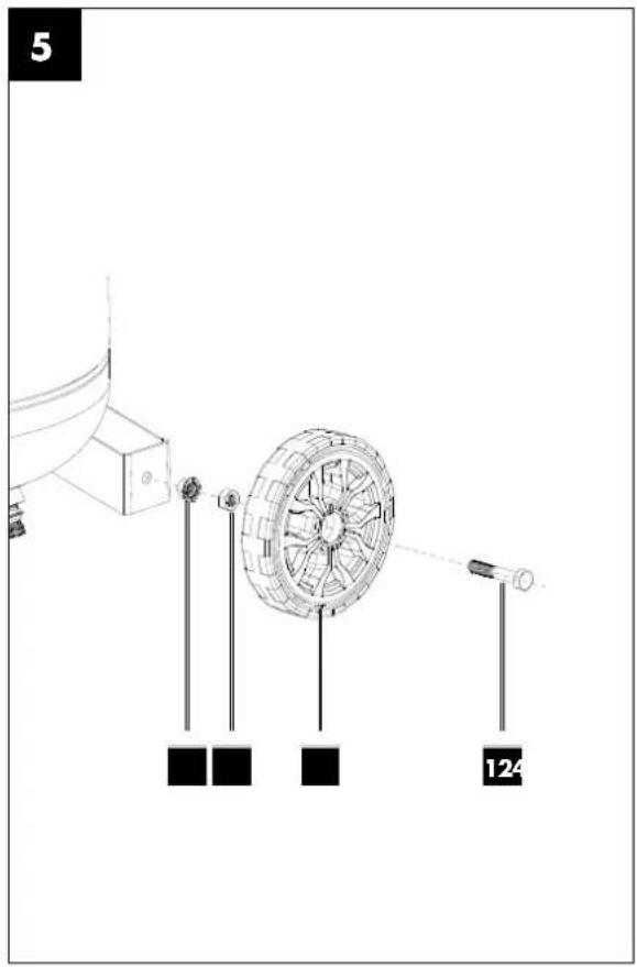
10.1 Installing the wheels (Fig. 5)
- Feed the wheel bolt (12) through the hole in the wheel (4).
- Screw the nut (B) onto the wheel bolt (12). Make sure that the wheel (4) can still be turned on the screw.
- Feed the wheel bolt (12) through the hole in the wheel linkage.
- Fasten the wheel (4) with the flange nut (D). If necessary, use an open-ended spanner (not included in the scope of delivery).
- Repeat the steps with the other tyre (4).
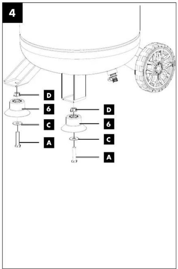
- Fit the enclosed feet (6) with the 2 hexagonal bolts (A), 2 washers (C) and 2 flange nuts (D) as shown in Fig. 4.
10.3 Mains power connection
- The compressor is equipped with a mains cable with an earthed plug. This can be connected to any mains socket 230V 50Hz with an earth contact and that is protected at 16 A.
- Before commissioning, ensure that the mains voltage matches with the operating voltage and the machine's power rating on the type plate.
- Long supply lines, as well as extensions, cable drums etc. cause voltage drop and can prevent the motor from starting.
- In the case of temperatures below +5^ C , motor starting can be endangered by sluggishness.
10.4 On/off switch (Fig. 2)
- The compressor is switched on by setting the on/off switch (8) to position I.
- The compressor is switched off by setting the on/off switch (8) to position 0.
10.5 Pressure adjustment: (Fig. 2)
- The actual pressure in the pressure vessel (3) is shown on the pressure gauge (11)
- The desired pressure can be adjusted using the manometer (10) which can be tapped at the quick-couplings (2).
- The set pressure can be read off the manometer (9).
- The pressure at the quick-coupling (2) can be adjusted from 0 to 10 bar.
10.6 Pressure switch adjustment
• The pressure switch is set in the factory.
- Switch-on pressure approx. 8 bar
- Switch-off pressure approx. 10 bar
10.7 Fitting the compressed air hose
- Push the compressed air hose into one of the two quick-couplers (2). The compressed air hose latches into place.
10.8 Dismantling the compressed air hose
- Press the coupling ring on the quick coupler (2) towards the device. The compressed air hose pops out of the quick-coupling (2).
Attention!
The compressed air hose is flung away depending on the pressure present in the compressor.
In order to prevent injury, hold the compressed air hose tightly immediately after the quick-coupling (2) when disassembling.
11. Using the accessories (included in the scope of delivery) (Fig. 7)
11.1 Spiral hose 5m (13)
Attention!
Never crush or kink the spiral hose (13). The spiral hose may get damaged.
⚠ Attention!
Do not use a damaged compressed air hoses. Damaged compressed air hoses can cause injuries.
11.1.1 Usage
- To assemble the spiral hose (13), insert the connection (13.1) of the spiral hose (13) into the quick-coupling (2) of the compressor (see 10.7).
- Insert a compressed air device, e.g. compressed air tyre inflation meter (14), into the quick-coupling (13.2).
- To dismantle, press the coupling ring on the quick-coupling (13.2) towards the hose. The compressed air device, e.g. compressed air tyre inflation meter (14), jumps out of the quick-coupling (13.2).
- To dismantle the compressed air hose on the compressor, see 10.8.
11.2 Compressed air tyre inflation meter (14)
Note
The compressed air required to fill a tire must be oil-free. No oiler may be connected in front of the device. It is better to use your own compressed air hose when working with the tire inflation meter, as there may still be oil residues in other compressed air hoses.
Note
Note that a tire pressure set, with the compressed air tyre inflation meter (14) must be checked again with a calibrated pressure gauge.
11.2.1 Mounting the compressed air tyre inflation meter (14)
The inflation hose (14.1) with valve plug connection (14.2) must be mounted to the compressed air tyre inflation meter (14).
- Screw the threaded connection of the inflation hose (14.1) into the mounting thread of the compressed air tyre inflation meter (14).
- Carefully tighten the threaded connection of the inflation hose (14.1).
11.2.2 Usage
The compressed air tyre inflation meter (14) has three functions:
• Pressure measurement
- Filling pressure
- Releasing pressure
Pressure measurement
- Place the valve plug connection (14.2) on the tyre valve. To do this, press the lever on the valve plug connection (14.2) to unlock the clamping mechanism.
- As soon as you release the lever, the valve plug connection (14.2) clamps on the tyre valve.
- The pressure can be read off at the pressure gauge (14.3). On the outer edge of the scale (14.4) you will find the unit bar (1bar = 100kPa).
- On the inner edge of the scale (14.4) you will find the unit PSI.
- Press the lever of the valve plug connection (14.2) again to release the valve plug connection from the valve.
Filling pressure
- Connect the connection (14.5) of the compressed air tyre inflation meter (14) to a compressed air hose, e.g. spiral hose (13) (see 11.1).
- Place the valve plug connection (14.2) on the tyre valve. To do this, press the lever on the valve plug connection (14.2) to unlock the clamping mechanism.
- As soon as you release the lever, the valve plug connection (14.2) clamps on the tyre valve.
- Press the trigger lever (14.6). Compressed air flows into the tire.
When filling, the pressure gauge (14.3.) shows a pressure slightly above the actual tyre pressure. As soon as you release the trigger lever (14.6), you can read off the actual tyre pressure on the pressure gauge (14.3).
Releasing pressure
If the tyre pressure is too high, press the air release button (14.7). Hereby, compressed air will be released. Lower the tyre pressure to the desired value.
11.3 Adapter set (15)
With the adapter set (15) you can inflate e.g. balls, air mattresses or bicycle tyres.
11.3.1 Usage
- Select the right adapter for your application from the adapter set (15).
- Attach the selected adapter to the valve plug connection (14.2) of the compressed air tyre inflation meter (14). To do this, press the lever on the valve plug connection (14.2) to unlock the clamping mechanism.
- As soon as you release the lever, the valve plug connection (14.2) clamps on the adapter.
- Press the lever of the valve plug connection (14.2) again to release the valve plug connection from the valve.
12. Electrical connection
The electrical motor installed is connected and ready for operation. The connection complies with the applicable VDE and DIN provisions. The customer's mains connection as well as the extension cable used must also comply with these regulations.
When working with spray attachments and during temporary use outdoors, the device must be connected to a residual current circuit breaker with a trigger current of 30 mA or less.
Damaged electrical connection cable
The insulation on electrical connection cables is often damaged.
This may have the following causes:
- Pressure points, where connection cables are passed through windows or doors.
- Kinks where the connection cable has been improperly fastened or routed.
- Places where the connection cables have been cut due to being driven over.
• Insulation damage due to being ripped out of the wall outlet.
- Cracks due to the insulation ageing.
Such damaged electrical connection cables must not be used and are life-threatening due to the insulation damage.
Check the electrical connection cables for damage regularly. Ensure that the connection cables are disconnected from electrical power when checking for damage. Electrical connection cables must comply with the applicable VDE and DIN provisions. Only use connection cables with the designation H05VV-F.
The printing of the type designation on the connection cable is mandatory.
Safety instructions for the replacement of damaged or defective power supply cables
Type X:
If the power cord of this device is damaged, it must be replaced by the manufacturer, their service department or a similarly qualified person to avoid dangers.
AC motor
• The mains voltage must be 230 V\~.
- Extension cables up to 25 m long must have a cross-section of 1.5 mm ^2 .
Connections and repair work on the electrical equipment may only be carried out by electricians.
• Type of current for the motor
• Machine data - type plate
• Engine data - type plate
13. Cleaning, maintenance, storage and ordering spare parts
⚠ Attention!
Pull out the mains plug before carrying out any cleaning or maintenance work! Danger of injury due to electric shocks!
⚠ Attention!
Wait until the device has cooled down completely! Danger of burning!
⚠ Attention!
Depressurise the device before carrying out any cleaning or maintenance work! Danger of injury!
13.1 Cleaning
- Keep the device as free of dust and dirt as possible. Rub the device clean with a clean cloth or blow it off with compressed air at low pressure.
- We recommend that you clean the device directly after every use.
- Clean the device at regular intervals using a damp cloth and a little soft soap. Do not use any cleaning products or solvents; they could attack the plastic parts of the device. Make sure that no water can penetrate the device interior.
- The hose and injection tools must be disconnected from the compressor before cleaning. The compressor must not be cleaned with water, solvents or similar.
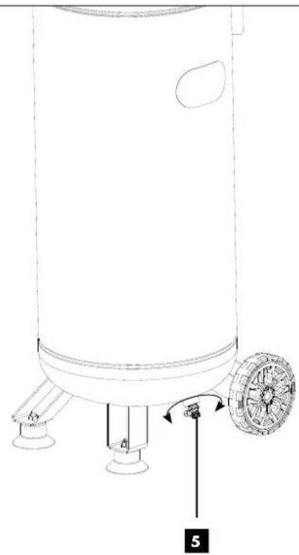
13.2 Maintenance of the pressure vessel (Fig. 3) ⚠ Attention!
To ensure a long service life for the pressure vessel (3), drain off the condensate after each use by opening the drain screw (5). Release the boiler pressure beforehand (see 13.4.1).
The drain screw (5) is opened by turning it anti-clockwise (when looking at the screw on the bottom of the compressor) so that the condensate can be completely drained out of the pressure vessel (3).
In order to drain the condensation water completely out of the pressure vessel (3), it must be tilted slightly to the side so that the drain screw (5) is the lowest point.
Then close the drain screw (5) again (turn clockwise). Check the pressure vessel (3) for rust and damage each time before use.
The compressor shall not be operated if the pressure vessel (3) is damaged or rusty. If you discover damage, please contact the customer service workshop.
The condensate from the pressure vessel may contain oil residue. Dispose of the condensate in an environmentally-friendly way at the appropriate collection point.
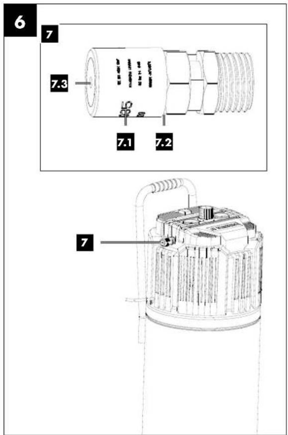
13.3 Safety valve (Fig. 1/6)
The safety valve (7) is set to the maximum permissible pressure of the pressure vessel (3). It is not permitted to adjust the safety valve (7) or to remove the connection lock (7.2) between the drain nut (7.1) and its cap (7.3).
In order for the safety valve (7) to function properly when needed, it must be actuated every 30 operating hours and at least 3 times a year.
Turn the drain nut (7.1) anti-clockwise to open the safety valve (7) drain.
The safety valve (7) now audibly lets out air. Then turn the drain nut (7.1) clockwise again to tighten.
13.4 Storage
⚠ Attention!
Disconnect the mains plug, vent the device and all connected compressed air tools. Store the compressor in such a way that it cannot be used by unauthorised persons.
Attention!
Store the compressor only in dry locations that are inaccessible for unauthorised persons. Do not tilt the unit, only store it upright!
13.4.1 Releasing overpressure
Release overpressure in the compressor by switching off the compressor and using up the compressed air still in the pressure vessel (3), e.g. with a compressed air tool running at idle or with an air blow gun.
13.5 Transport (Fig. 1)
The compressor can be tilted it up by means of the transport handle (1) so that it can be transported on the wheels (4).
13.6 Ordering spare parts
Please provide the following information when ordering spare parts;
- Device type
• Device article number
With this product, it is necessary to note that the following parts are subject to natural or usage-related wear, or that the following parts are required as consumables.
Wearing parts*: Clutch
* may not be included in the scope of supply!
14. Disposal and recycling
The device is supplied in packaging to avoid transport damages. This packaging is raw material and can thus be used again or can be reintegrated into the raw material cycle.
The device and its accessories are made of different materials, such as metal and plastic. Take defective components to special waste disposal sites. Check with your specialist dealer or municipal administration!

The packaging is made of environmentally friendly materials that can be disposed of at your local recycling centre.
You can find out how to dispose of the disused device from your local authority or city administration.
Do not throw old equipment away with household waste!

This symbol indicates that this product must not be disposed of in household waste as per Waste Electrical and Electronic Equipment directive (2012/19/EU) and national laws. This product must be handed over at the end collection point. This can be done, for example, by using it when purchasing a similar product or delivering it to harmonised collection point for the recycling of old electrical electronic devices. Improper handling of old devices can negative effects on the environment and on human health potential hazardous materials which are often contain in old electrical and electronic devices. By disposing of product properly, you are also contributing to the effective natural resources. Information about collection points for devices can be found at your municipal authority, the local provider, an authorised location for the disposal of old electrical and electronic devices or your waste collection ser-
15. Troubleshooting
| Fault Possible cause Remedy |
| Compressor does not run. | Mains voltage not present. Check cable, mains plug, fuse and socket. | |
| Mains voltage too low. | Avoid extension cables that are too long. Use extension cables with sufficient conductor cross-section. |
| Outdoor temperature too low. | Do not operate at outside temperatures below 0°C. |
| Motor overheating. | Let the motor cool down, if necessary, eliminate the cause of overheating. |
| Compressor runs, but no pressure. | Non-return valve leaking Replace the non-return valve. | |
| Seals defective. | Replace the seals, have defective seals replaced at a specialist workshop. |
| Drain screw for condensate leaking. | Tighten the screw by hand. Check the seal on the screw and replace if necessary. |
| Compressor running, pressure shown on the manometer, but tools are not running. | Hose connections leaking. | Check compressed air hose and tools, replace if necessary. |
| Quick-coupler leaking. | Check quick coupling, replace if necessary. |
| Pressure set too low at pressure regulator. Turn up | the pressure regulator further. |
16. Warranty certificate
Dear Customer,
All of our products undergo strict quality checks to ensure that they reach you in perfect condition. In the unlikely event that your device develops a fault, please contact our service department at the address shown on this guarantee card. Of course, if you would prefer to call us then we are also happy to offer our assistance under the service number printed below. Please note the following terms under which guarantee claims can be made:
- These guarantee terms cover additional guarantee rights and do not affect your statutory warranty rights. We do not charge you for this guarantee.
- Our guarantee only covers problems caused by material or manufacturing defects, and it is restricted to the rectification of these defects or replacement of the device. Please note that our devices have not been designed for use in commercial, trade or industrial applications. Consequently, the guarantee is invalidated if the equipment is used in commercial, trade or industrial applications or for other equivalent activities. The following are also excluded from our guarantee: compensation for transport damage, damage caused by failure to comply with the installation/assembly instructions or damage caused by unprofessional installation, failure to comply with the operating instructions (e.g. connection to the wrong mains voltage or current type), misuse or inappropriate use (such as overloading of the device or use of non-approved tools or accessories), failure to comply with the maintenance and safety regulations, ingress of foreign bodies into the device (e.g. sand, stones or dust), effects of force or external influences (e.g. damage caused by the device being dropped) and normal wear resulting from proper operation of the device.
The guarantee is rendered null and void if any attempt is made to tamper with the device.
- The guarantee is valid for a period of 3 years starting from the purchase date of the device. Guarantee claims should be submitted before the end of the guarantee period within two weeks of the defect being noticed. No guarantee claims will be accepted after the end of the guarantee period. The original guarantee period remains applicable to the device even if repairs are carried out or parts are replaced. In such cases, the work performed or parts fitted will not result in an extension of the guarantee period, and no new guarantee will become active for the work performed or parts fitted. This also applies when an on-site service is used.
- In order to assert your guarantee claim, please contact the service partner shown below. If the complaint is within the guarantee period, we will provide you with a return slip, with which you can return your defective device free of charge to us. It would help us if you could describe the nature of the problem in as much detail as possible. If the defect is covered by our guarantee then your device will either be repaired immediately and returned to you, or we will send you a new device.
Of course, we are also happy offer a chargeable repair service for any defects which are not covered by the scope of this guarantee or for units which are no longer covered. To take advantage of this service, please send the device to our service address.
Service-Hotline (GB): Service-Hotline (IE):
00800 4003 4003 00800 4003 4003
(0,00 EUR/Min.) (0,00 EUR/Min.)
Service-Email (GB): Service-Email (IE):
service.GB@scheppach.com
service.IE@scheppach.com
Service Address (GB): Service Address (IE):
Forest Park & Garden LetMeRepair
Coed Court, Taffsmead Road 1 Langlands Court / Kelvin South Business Park
Treforest, Ind. Estate, Pontypridd CF375SW East Kilbride G75 0YB

text_image
PDF ONLINE
www.lidl-service.com
At www.lidl-service.com you can download this and many more manuals, product videos plus installation software.
The QR code takes you directly to the Lidl service page (www.lidl-service.com) and you can open your operating manual by entering the article number (IAN) 373215_2104.
Inhalt:
Seite:
Günzburger Straße 69
D-89335 Ichenhausen
Verehrter Kunde
13.5 Transport (Abb. 1)
service.AT@scheppach.com
service.CH@scheppach.com
Service Adresse (DE): Service Adresse (AT):
Günzburger Straße 69
D-89335 Ichenhausen
Cher client,
13.5 Transport (fig.1)
Service-hotline (BE):
00800 4003 4003
(0,00 €/Min.)
Email du service (FR):
service.FR@scheppach.com
E-mailadres (BE):
service.BE@scheppach.com
Scheppach France Strassburg
2, Impasse Jean Millot
FR - 6700 Strasbourg
Serviceadres (BE):
Service Center Bruyninckx
Guldendelle 30
BE - 1930 Zventem (Nossegem)

text_image
PDF ONLINE
www.iidl-service.com
Günzburger Straße 69
D-89335 Ichenhausen
Geachte klant,
13.5 Transport (afb. 1)
service.NL@scheppach.com
Serviceadres / Adresse du service (NL):
Günzburger Straße 69
D-89335 Ichenhausen
Vážený zákazníku,
Günzburger Straße 69
D-89335 Ichenhausen
Szanowny Kliencie,
13.5 Transport (rys. 1)
Günzburger Straße 69
D-89335 Ichenhausen
Vážený zákazník,
Günzburger Straße 69
Günzburger Straße 69
D-89335 Ichenhausen
Kære kunde,
13.5 Transport (fig. 1)
Kompressoren kan transporteres ved at kippe transportgrebet (1) ned på hjulene (4).
13.6 Bestilling af reservedele
Husk at angive følgende oplysninger, når der bestilles reservedele;
text_image
Technical diagram of a mechanical device with numbered parts and exploded view, showing internal components and assembly relationships.
Translation of the original CE declaration of conformity
Standard references:
EN 1012-1:2010; EN 62841-1:2015; EN 61000-6-1:2007; EN IEC 61000-6-1:2019; EN 61000-6-3:2007/A1:2011
This declaration of conformity is issued under the sole responsibility of the manufacturer.
Subject to change without notice
Documents registrar: Thomas Schuster
Günzburger Str. 69, D-89335 Ichenhausen
CE