PDST 10 B3 - Air compressor PARKSIDE - Free user manual and instructions
Find the device manual for free PDST 10 B3 PARKSIDE in PDF.

| Product type | Pneumatic maintenance unit (compressed air conditioner) |
| Brand | Parkside |
| Model | PDST 10 B3 |
| Maximum operating pressure | 8 bar |
| Pressure adjustment range | 0.5 to 8 bar |
| Input connection | Male connector (pre-assembled) |
| Output connection | Quick-release coupling |
| Oil reservoir capacity | Approximately 100 ml (estimate) |
| Condensate collection reservoir capacity | Approximately 200 ml (estimate) |
| Recommended oil | Compressor oil |
| Supplied material | 1 maintenance unit, 2 mounting screws, 2 wall plugs, 1 instruction manual |
| Intended use | For compressed air tools, domestic use only |
| Prohibited applications | Explosive environments, with grease guns, sandblasters, etc. |
| Main functions | Filtration, pressure regulation, compressed air lubrication |
| Maintenance and cleaning | Regularly drain condensate, clean with a damp cloth |
| Safety | Disconnect power supply before maintenance, do not exceed 8 bar |
| Warranty period | 3 years from date of purchase |
| After-sales service France | Tel. 0800 919270, email kompernass@lidl.fr |
Frequently Asked Questions - PDST 10 B3 PARKSIDE
User questions about PDST 10 B3 PARKSIDE
0 question about this device. Answer the ones you know or ask your own.
Ask a new question about this device
Download the instructions for your Air compressor in PDF format for free! Find your manual PDST 10 B3 - PARKSIDE and take your electronic device back in hand. On this page are published all the documents necessary for the use of your device. PDST 10 B3 by PARKSIDE.
USER MANUAL PDST 10 B3 PARKSIDE
text_image
PDF ONLINE www.lidl-service.com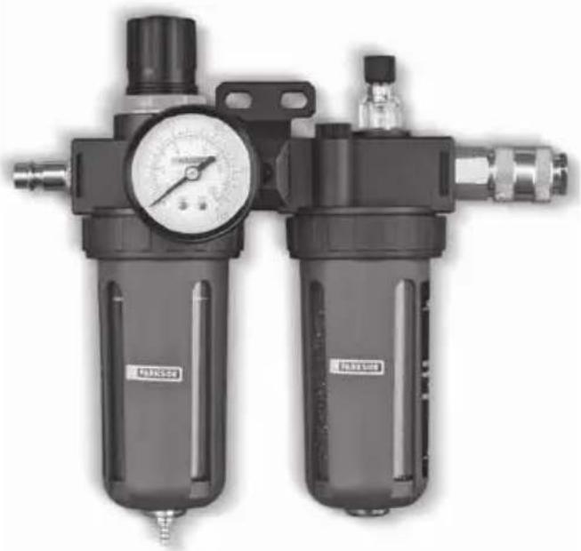
natural_image
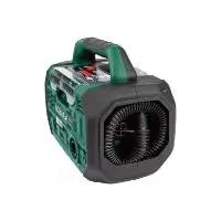
Close-up of a black industrial air filter control unit with pressure gauge and side washers (no visible text or symbols)AIR FILTER REGULATOR & LUBRICATOR / DRUCKLUFT-WARTUNGSEINHEIT / UNITÉ DE MAINTENANCE PNEUMATIQUE PDWE 8 B2
GB
AIR FILTER REGULATOR & LUBRICATOR
Translation of the original instructions
FR
UNITÉ DE MAINTENANCE PNEUMATIQUE
Before reading, unfold the page containing the illustrations and familiarise yourself with all functions of the device.
DE
GB Translation of the original instructions Page 1
| DE | Originalbetriebsanleitung | Seite | 11 |
| FR | Traduction des instructions d'origine Page 21 | ||
| NL | Vertaling van de originele gebruiksaanwijzing Pagina 33 | ||
| CZ | Překlad originálního provozního návodu Strana 43 | ||
| PL | Tłumaczenie oryginalnej instrukcji obsługi | Strona 53 | |
| SK | Preklad originálneho návodu na obsluhu | Strana 63 | |
| ES | Traducción del manual de instrucciones original | Página 73 | |
| DK | Oversættelse af den originale driftsvejledning | Side 83 |
text_image
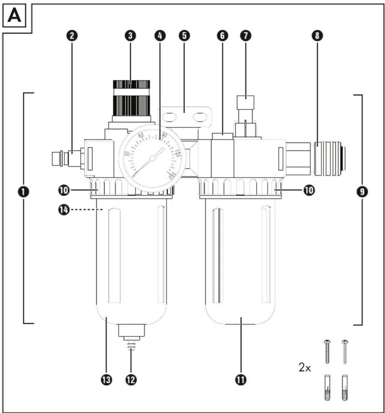
A 1 2 3 4 5 6 7 8 9 10 10 14 13 12 11 2x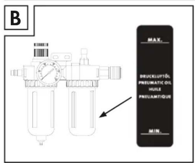
text_image
B MAX. DRUCKLUPTÖL PNEUMATIC OIL HUILE PNETUAMTIQUE MIN.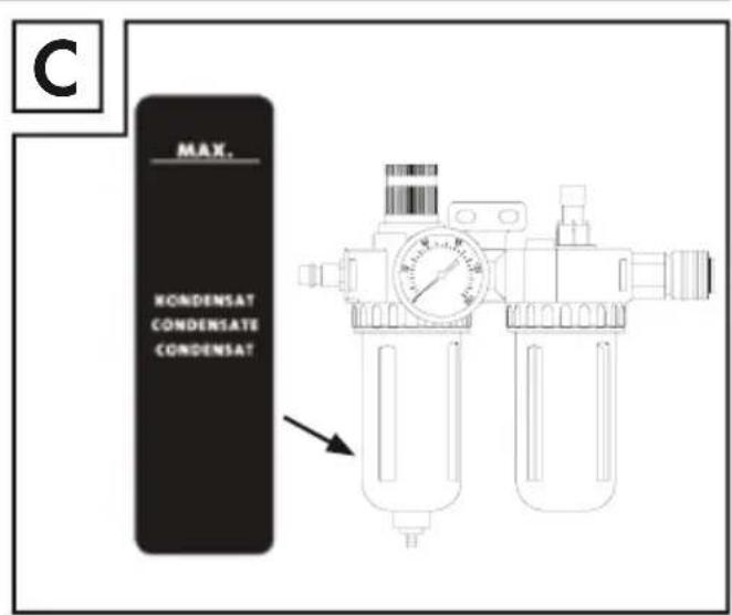
text_image
C MAX. KONDENSAT CONDENSATE CONDENSATContents
Introduction 2
Intended use 2
Features 2
Package contents 2
Technical specifications 2
General safety instructions for compressed air tools....3
Safety instructions for the use of compressed air appliances. 3
User safety 4
Prohibited areas of application 4
Important note 4
Before use 4
Installation 4
Filling the oil mister unit 5
Use 5
Setting the working pressure 6
Filter unit 6
Draining condensate using the drain valve 6
Oil mister unit 7
Maintenance and cleaning 7
Disposal 8
Kompernass Handels GmbH warranty 8
Service....9
Importer....9
AIR FILTER REGULATOR & LUBRICATOR PDWE 8 B2
Introduction
Congratulations on the purchase of your new appliance. You have chosen a high-quality product. The operating instructions are part of this product. They contain important information about safety, usage and disposal. Before using the product, please familiarise yourself with all of the operating and safety instructions. Use the product only as described and for the range of applications specified. Please also pass these operating instructions on to any future owner.
Intended use
The compressed air maintenance unit is used to oil the compressed air for compressed air tools, and filters out condensate from the compressed air at the same time. Use the product only as described and for the range of applications specified. Retain these instructions for future reference. Pass all relevant documents to any future owner. Any use which deviates from the intended use is prohibited and potentially dangerous. Damage caused by failure to observe the instructions or misuse is not covered by the warranty and does not fall under the manufacturer's liability. The appliance is designed for domestic use and must not be used for commercial or industrial purposes.
Symbols on the compressed air tool
 | Read the operating instructions before use. |
 | Wear a dust mask. |
 | Wear protective goggles. |
 | Wear hearing protection. |
 | Wear protective gloves. |
Features
① Filter unit
② Connector nipple (pre-assembled)
③ Air pressure regulator
4 Compressed air manometer
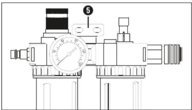
⑤ Wall bracket
6 Oil refill inlet
⑦ Oil outlet screw
8 Quick coupling
⑨ Oil mister unit
10 Locking ring
⑪ Container for compressed air oil
12 Drain valve
13 Condensate collector
14 Filter insert
Package contents
1 air Filter Regulator & Lubricator including connections
1 mounting accessories
(2x mounting screws, 2x wall plugs)
1 set of operating instructions
Technical specifications
Working pressure max. 8 bar Oil suitable compressor oil
Generalsafety instructions for compressed air tools

WARNING!
▶ PLEASE READ THE OPERATING INSTRUCTIONS CAREFULLY BEFORE USE. THEY ARE A PART OF THIS APPLIANCE AND MUST BE AVAILABLE AT ALL TIMES!
The type plate shows all technical data of this compressed air maintenance unit, please inform yourself about the technical conditions of this appliance.
This appliance may be used by people aged 16 years and above and by people with limited physical, sensory or mental capabilities or lack of experience and knowledge, provided that they are under supervision or have been told how to use the appliance safely and are aware of the potential risks. Do not allow children to use the appliance as a plaything. Cleaning and user maintenance tasks may not be carried out by children unless they are supervised.
The compressed air maintenance unit is used in conjunction with a compressor for the maintenance and care (e.g. filtering, oiling and regulating) of your compressed air tools. The compressed air maintenance unit may only be used with a compressed air compressor. When using the unit, observe the maximum compressed air values of the connected tools and check these several times during use. This product is intended for private use only. The compressed air maintenance unit may only be used for its intended purpose. Any other use deviating from this is prohibited!
■ Proper use also involves compliance with the safety instructions as well as the assembly instructions contained in the operating instructions. The manufacturer or dealer accepts no liability for damage caused by improper or incorrect use.
■ Use only accessories suitable for this product. People who use the compressed air maintenance unit and carry out any maintenance work must familiarise themselves with it. They must also be informed of potential hazards. The applicable accident prevention regulations must be observed correctly and conscientiously.
■ Any changes made to the compressed air maintenance unit will preclude any liability on the part of the manufacturer for any associated damage.
Safety instructions for the use of compressed air appliances

RISK OF INJURY!
▶ Disconnect the compressed air supply before changing tools, adjusting and servicing.
▶ When undoing a connection, always hold the compressed air hose firmly in your hands. Injuries may occur due to the compressed air hose whipping back.
The compressed air maintenance unit must be installed before it can be put safely into operation. A stable wall is suitable for mounting (with screws).
■ We recommend using only lubricants specified by the manufacturer.
■ Never exceed the specified maximum pressure values of the compressed air maintenance unit.
■ The compressed air maintenance unit may only be connected to a compressed air source which does not exceed the working pressure of 8 bar.
■ Do not place the compressed air lines near heat, oil or sharp edges.
The compressed air maintenance unit may only be operated in conjunction with a compressed air compressor. The use of other compressed air sources, such as a compressed air cylinder, is prohibited. There is a risk of fire and/or explosion.
■ Make sure that you keep children and people with limited physical or mental abilities away from the compressed air maintenance unit and connected compressed air tools.
■ Use only original spare parts for repairs. Non-original spare parts can cause serious damage.
■ When carrying out maintenance, adjustment and repair work, always disconnect the compressed air maintenance unit from the compressed air supply first.
■ Modifications to the compressed air maintenance unit are prohibited.
- Do not use the compressed air maintenance unit unless it is in perfect condition. If in doubt, consult a specialist before using the appliance.
■ Have all repairs carried out by qualified professionals.
User safety
■ Before each application, test the compressed air tool you are using.
Do not use the compressed air maintenance unit with a higher operating pressure than that indicated in the technical data. Before connecting your air tools to the compressed air maintenance unit, make sure they are properly and securely connected.
Prohibited areas of application
- Do not use this compressed air maintenance unit in potentially explosive atmospheres. Avoid working in environments containing substances such as flammable gases, liquids, and paint or dust mists. These substances can be ignited by very hot surfaces on the compressed air unit.
Important note
- Do not use the compressed air maintenance unit in conjunction with compressed air appliances that are suitable for use with processed compressed air (e.g. grease guns, sandblasting devices, tyre inflators, etc.).
Before use
Installation
NOTE: To minimise potential injury or damage, the compressed air maintenance unit must be mounted on a suitable wall prior to initial operation. Ensure the compressed air maintenance unit is mounted stably and horizontally.
For wall mounting, use the wall bracket ⑤ for marking on the wall and for screwing with the supplied mounting material (see scope of delivery, see fig. D).
text_image
Technical diagram of a pressure relief valve with labeled component 5 and pressure gauge(fig. D)
Filling the oil mister unit

CAUTION!
▶ Before filling or removing the oil reservoir ⑪ make sure that the compressed air maintenance unit has been disconnected from the compressed air source.
Remove the oil reservoir ⑪ by turning the locking ring ⑩ clockwise (see fig. E). Fill the oil reservoir ⑪ with suitable compressor oil until the max. marking is reached (see Fig. B).
- Then manually rotate the oil reservoir anticlockwise to the desired position ⑪ (do not use tools).
natural_image
Technical diagram of a pressure regulator with gauges and housing, showing mechanical components and directional arrow (no text or labels)(fig. E)
Use

CAUTION!
▶ Ensure that the connected compressed air line is clean and oil-free so that the compressed air maintenance unit can be used properly. Also make sure that the compressed air system is pressure-free. In order to minimise pressure losses, it is preferable to keep the compressed air lines as short as possible.
- Connect the compressed air maintenance unit to the compressed air source.
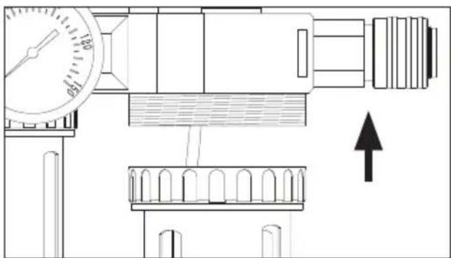
- First release the locking device by pulling the air pressure regulator ③ upwards (see Fig. F).
Set the air pressure regulator ③ to the lowest setting by rotating it anticlockwise. The desired settings are adopted by pressing the air pressure regulator ③ downwards.
Connect the compressed air supply line of the tool to be connected to the quick coupling ⑧ (on the right side - output) of the compressed air maintenance unit. A triangle "▶" on the surface of the unit indicates the flow direction of the compressed air.
Connect the compressed air supply line of the compressed air source via the connector nipple ② (on the left side inlet) of the compressed air maintenance unit. A triangle "▶" is marked on the surface in close proximity to the inlet, which indicates the flow direction of the compressed air.
natural_image
Technical line drawing of a mechanical pressure regulator with valve and gauges (no text or symbols)(fig. F)
Before using the compressed air maintenance unit, check the direction of the compressed air flow using the "▶" mark on the surface. Incorrect installation will not generate sufficient pressure.
Setting the working pressure
After connecting the compressed air maintenance unit to a compressed air source, you can adjust the desired operating pressure by using the air pressure regulator ③.
The applied working pressure of the compressed air source is displayed on the compressed air pressure gauge ④.
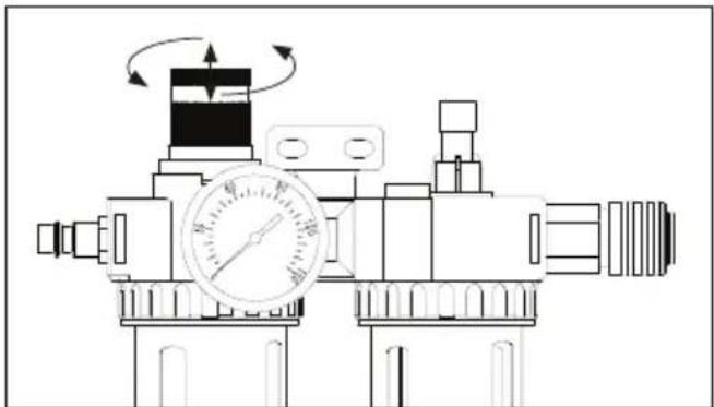
- First release the locking device by pulling the air pressure regulator ③ upwards (see fig. F).
♦ Turn anticlockwise to reduce the pressure. Turn clockwise to increase the pressure.
Read the pressure setting from the compressed air manometer 4.
◆ Lock the setting by pushing the air pressure regulator ③ downward.
NOTE
▶ Make sure that the maximum possible operating pressure of the compressed air maintenance unit and the compressed air tool used is not exceeded.
Filter unit
The filter unit ① is connected to the air pressure regulator ③. The maximum working pressure is 8 bar and the working pressure is adjustable from 0.5 to 8 bar. The filter unit ① is used to filter condensate and stores the condensate in the condensate collector ⑬.
The fill level of the condensate can be inspected through the transparent viewing window (see fig. C). The stored condensate can be discharged via the drain valve 12.
Draining condensate using the drain valve
Ensure that the compressed air maintenance unit is mounted horizontally so that the condensate can also be collected horizontally in the condensate collector ⑬. Do not use the filter unit ① if the condensate collector ⑬ is not fitted.
NOTE
Before emptying the condensate collector 13, make sure the compressed air maintenance unit has been disconnected from the compressed air source. Otherwise, the collected condensate may spray out in an uncontrolled manner.
The drain valve ⑫ opens as soon as it is disconnected from the compressed air.
In order to drain the stored condensate from the condensate collector ⑬, use an appropriate container.
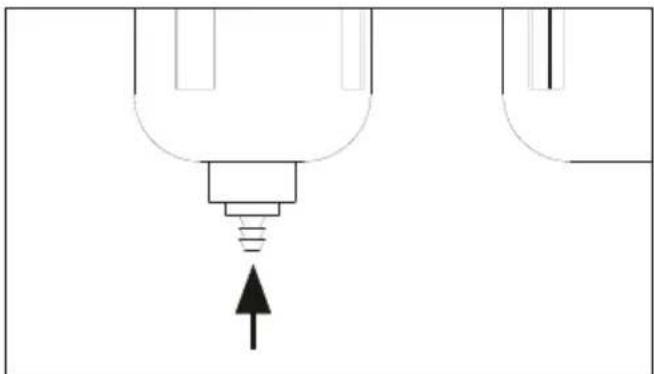
Press against the drain valve 12 from below (see fig. G), it will open and the condensate will flow into the container.
natural_image
Pure diagram of a mechanical component with an upward arrow, no text or symbols present(fig. G)
Oil mister unit
The oil mister unit ⑨ is connected to the filter unit ①. Its function is to lubricate the filtered compressed air which is being transported in the direction of the compressed air tool.
The fill level of the oil reservoir ⑪ (integrated in the oil mister unit) can be inspected through the transparent viewing window. Use only oil that is suitable for this compressed air maintenance unit (see above).
Turn the oil outlet screw ⑦ (mounted on the sight glass) clockwise ("−") to reduce the amount of oil required. Turn it anticlockwise (+") to increase the amount of oil.
The integrated sight glass makes continuous monitoring of the filtered compressed air possible.
To top up the oil, unscrew the screw of the oil refill inlet ⑥ with a suitable Allen key. Fill the container with the help of a suitable funnel and then replace the screw using the Allen key.
| Fault Causes | The solution | |
| Insufficient lubrication. | Oil outletscrew 7 turned too far in direction("-"). | Increase the oil quantity |
| The compressed air oil quantity is too low, i.e. below the minimum fill quantity. | Pour more oil into the oil reservoir 11. Pay attention to the maximum filling quantity. | |
| The operating pressure of the compressed air is too weak. | The pressure regulator 3 is closed too tightly. | Increase the pressure. |
Maintenance and cleaning

WARNING! RISK OF INJURY! Disconnect the appliance from the compressed air supply.
NOTE
The compressed air maintenance unit must be serviced and overhauled at regular intervals to ensure proper functioning and compliance with safety requirements. Improper and incorrect operation can lead to failures and damage to the appliance.
■ Never use harsh and/or abrasive cleaning agents or solvents. These could damage the plastic parts of the compressed air maintenance unit.
■ Never allow water to get inside the oiler.
■ Make sure that the housing and the inside of the compressed air maintenance unit remain free of dust and dirt. To ensure this is the case, wipe the compressed air maintenance unit regularly with a clean cloth.
■ Clean the compressed air maintenance unit and the connections at regular intervals with a damp cloth.
■ Empty the tank of the compressed air maintenance unit at regular intervals. To do this, press the drain valve 12 (see fig. G) on the underside upwards. Please note that the compressed air maintenance unit must be pressure-free for safety reasons.
Disconnect the compressed air maintenance unit from the compressed air source.
The drain valve 12 opens as soon as it is disconnected from the compressed air.
Disposal

The packaging consists of environmentally friendly material. It can be disposed of in local recycling containers.
Do not dispose of the appliance in the normal domestic waste!
Your local community or municipal authorities can provide information on how to dispose of the worn-out appliance.

Dispose of the packaging in an environmentally friendly manner. Note the labelling on the packaging and separate the packaging material components for disposal if necessary. The packaging material is labelled with abbreviations (a) and numbers (b) with the following meanings: 1–7: plastics, 20–22: paper and cardboard, 80–98: composites.

Your local community or municipal authorities can provide information on how to dispose of the worn-out product.

The product is recyclable, subject to extended producer responsibility and is collected separately.
This appliance has a 3-year warranty valid from the date of purchase. If this product has any faults, you, the buyer, have certain statutory rights. Your statutory rights are not restricted in any way by the warranty described below.
Warranty conditions
The warranty period starts on the date of purchase. Please keep your receipt in a safe place. This will be required as proof of purchase.
If any material or manufacturing fault occurs within three years of the date of purchase of the product, we will either repair or replace the product for you or refund the purchase price (at our discretion).
This warranty service requires that you present the defective appliance and the proof of purchase (receipt) within the three-year warranty period, along with a brief written description of the fault and of when it occurred.
If the defect is covered by the warranty, your product will either be repaired or replaced by us. The repair or replacement of a product does not signify the beginning of a new warranty period.
Warranty period and statutory claims for defects
The warranty period is not prolonged by repairs effected under the warranty. This also applies to replaced and repaired components. Any damage and defects present at the time of purchase must be reported immediately after unpacking. Repairs carried out after expiry of the warranty period shall be subject to a fee.
Scope of the warranty
This appliance has been manufactured in accordance with strict quality guidelines and inspected meticulously prior to delivery.
The warranty covers material faults or production faults. The warranty does not extend to product parts subject to normal wear and tear or to fragile parts which could be considered as consumable parts such as switches or parts made of glass.
The warranty does not apply if the product has been damaged, improperly used or improperly maintained. The directions in the operating instructions for the product regarding proper use of the product are to be strictly followed. Uses and actions that are discouraged in the operating instructions or which are warned against must be avoided.
This product is intended solely for private use and not for commercial purposes. The warranty shall be deemed void in cases of misuse or improper handling, use of force and modifications / repairs which have not been carried out by one of our authorised Service centres.
The warranty period does not apply to
■ Normal reduction of the battery capacity over time
■ Commercial use of the product
■ Damage to or alteration of the product by the customer
■ Non-compliance with safety and maintenance instructions, operating errors
■ Damage caused by natural hazards
Warranty claim procedure
To ensure quick processing of your case, please observe the following instructions:
■ Please have the till receipt and the item number (IAN) 373204_2104 available as proof of purchase.
■ You will find the item number on the type plate on the product, an engraving on the product, on the front page of the operating instructions (below left) or on the sticker on the rear or bottom of the product.
If functional or other defects occur, please contact the service department listed either by telephone or by e-mail.
■ You can return a defective product to us free of charge to the service address that will be provided to you. Ensure that you enclose the proof of purchase (till receipt) and information about what the defect is and when it occurred.

You can download these instructions along with many other manuals, product videos and installation software at www.lidl-service.com.
This QR code will take you directly to the Lidl service page (www.lidl-service.com) where you can open your operating instructions by entering the item number (IAN) 373204_2104.
NOTE
For Parkside tools, please send us only the defective item without the accessories (e.g. battery, storage case, assembly tools, etc.).
Service
GB Service Great Britain
Tel.: 0800 404 7657
E-Mail: kompernass@lidl.co.uk
IE Service Ireland
Tel.: 1890 930 034
(0,08 EUR/Min., (peak))
(0,06 EUR/Min., (off peak))
E-Mail: kompernass@lidl.ie
IAN 373204_2104
Importer
Please note that the following address is not the service address. Please use the service address provided in the operating instructions.
KOMPERNASS HANDELS GMBH
BURGSTRASSE 21
44867 BOCHUM
GERMANY
www.kompernass.com
Inhaltsverzeichnis
Einleitung 12
text_image
Technical diagram of a pressure relief valve with labeled component 5 and pressure gauge(Abb. D)
natural_image
Technical diagram of a mechanical device with pressure gauge and directional arrow (no text or symbols)(Abb. E)
Inbetriebnahme

ACHTUNG!
natural_image
Technical line drawing of a mechanical pressure regulator with valve and gauges (no text or symbols)(Abb. F)
natural_image
Pure diagram of a light bulb with an arrow pointing upward, no text or symbols present(Abb. G)
Ölneblereinheit
KOMPERNASS HANDELS GMBH
BURGSTRASSE 21
44867 BOCHUM
DEUTSCHLAND
www.kompernass.com
Table des matières
Introduction 22
text_image
Technical diagram of a pressure relief valve with labeled component 5 and pressure gauge(Fig. D)
natural_image
Technical diagram of a pressure regulator with gauges and housing (no text or labels)(Fig. E)
Mise en service

ATTENTION!
natural_image
Technical line drawing of a mechanical pressure regulator with valve and gauges (no text or symbols)(Fig. F)
natural_image
Pure diagram of a lamp with an arrow pointing to it, no text or symbols present(Fig. G)
KOMPERNASS HANDELS GMBH
BURGSTRASSE 21
44867 BOCHUM
ALLEMAGNE
www.kompernass.com
Inhoud
Inleiding....34
text_image
Technical diagram of a pressure regulator with labeled component 5 and dial indicator(Afb. D)
natural_image
Technical diagram of a mechanical device with pressure gauge and directional arrow (no text or symbols)(Afb. E)
Ingebruikname

LET OP!
natural_image
Technical line drawing of a mechanical pressure regulator with valve and gauges (no text or symbols)(Afb. F)
natural_image
Pure diagram of a mechanical component with an upward arrow, no text or symbols present(Afb. G)
Olievernevelaar
KOMPERNASS HANDELS GMBH
BURGSTRASSE 21
44867 BOCHUM
DUITSLAND
www.kompernass.com
Obsah
Úvod 44
text_image
Technical diagram of a pressure regulator with labeled component 5 and measurement dial(Obr. D)
natural_image
Technical diagram of a mechanical device with pressure gauge and directional arrow (no text or symbols)(Obr. E)
Uvedení do provozu

POZOR!
natural_image
Technical line drawing of a mechanical pressure regulator with valve and gauges (no text or symbols)(Obr. F)
natural_image
Pure diagram of a mechanical component with an upward arrow, no text or symbols present(Obr. G)
KOMPERNASS HANDELS GMBH
BURGSTRASSE 21
44867 BOCHUM
NĚMECKO
www.kompernass.com
Spis treści
Wstep....54
text_image
Technical diagram of a pressure relief valve with labeled component 5 and pressure gauge(Rys. D)
natural_image
Technical diagram of a pressure regulator with gauges and adjustment knobs (no text or labels)(rys. E)
Uruchomienie

UWAGA!
natural_image
Technical line drawing of a mechanical pressure regulator with valve and gauges (no text or symbols)(Rys. F)
natural_image
Pure diagram of a lamp with an arrow pointing to it, no text or symbols present(Rys. G)
KOMPERNASS HANDELS GMBH
BURGSTRASSE 21
44867 BOCHUM
NIEMCY
www.kompernass.com
Obsah
Úvod 64
text_image
Technical diagram of a pressure regulator with labeled component 5 and measurement dial(Obr. D)
natural_image
Technical diagram of a pressure regulator with gauges and housing, showing mechanical components and directional arrow (no text or labels)(Obr. E)
natural_image
Technical line drawing of a mechanical pressure regulator with directional arrows indicating motion (no text or symbols)(Obr. F)
natural_image
Pure electrical circuit lines without any symbols(Obr. G)
KOMPERNASS HANDELS GMBH
BURGSTRASSE 21
44867 BOCHUM
NEMECKO
www.kompernass.com
Índice
Introducción 74
Uso previsto 74
Equipamiento 74
Volumen de suministro....74
text_image
Technical diagram of a pressure regulator with labeled component 5 and dial indicator(Fig. D)
natural_image
Technical diagram of a mechanical device with pressure gauge and directional arrow (no text or labels)(Fig. E)
natural_image
Technical line drawing of a mechanical pressure regulator with rotating dial (no text or symbols)(Fig. F)
natural_image
Pure diagram of a mechanical component with an upward arrow, no text or symbols present(Fig. G)
KOMPERNASS HANDELS GMBH
BURGSTRASSE 21
44867 BOCHUM
ALEMANIA
www.kompernass.com
Indholdsfortegnelse
Indledning 84
text_image
Technical diagram of a pressure relief valve with labeled component 5 and pressure gauge(Fig. D)
natural_image
Technical diagram of a mechanical device with pressure gauge and directional arrow (no text or symbols)(Fig. E)
Ibrugtagning

OBS!
natural_image
Technical line drawing of a mechanical pressure regulator with valve and gauges (no text or symbols)(Fig. F)
natural_image
Pure diagram of a mechanical component with an upward arrow, no text or symbols present(Fig. G)
Tågesmører
KOMPERNASS HANDELS GMBH
BURGSTRASSE 21
44867 BOCHUM
TYSKLAND
www.kompernass.com

KOMPERNASS HANDELS GMBH
BURGSTRASSE 21
44867 BOCHUM
GERMANY
www.kompernass.com
Last Information Update · Stand der Informationen · Version des informations · Stand van de informatie
Stav informaci · Stan informacji · Stav informacií · Estado de las informaciones · Tilstand af information:
08 / 2021 · Ident.-No.: PDWE8B2-072021-1