DSCAG 125 FH - Slicer FESTOOL - Free user manual and instructions
Find the device manual for free DSCAG 125 FH FESTOOL in PDF.

| Product type | Diamond saw |
| Brand | Festool |
| Model | DSC-AG 125 FH |
| Tool diameter | 125 mm |
| Cutting depth | 27 mm |
| Weight (angle grinder) | 2.3 kg |
| Weight (dust hood) | 0.6 kg |
| Power supply | 220-240 V~, 50/60 Hz |
| Power consumption | 1400 W |
| No-load speed | 3500 - 11000 min-1 |
| Max. peripheral speed | 80 m/s |
| Spindle thread | M14 |
| Dust extraction connection | 27/36 mm |
| Protection class | II |
| Electronic functions | Soft start, speed regulation, kickback protection, anti-vibration (VIBRASTOP), constant speed, restart protection, thermal overload protection |
| Safety | Dust hood, tilting hood with kickback lever, auxiliary handle, spindle stop, safety switch |
| Sound pressure level | LPA = 90 dB(A) |
| Sound power level | LWA = 101 dB(A) |
| Vibration emission (cutting) | ah = 4.0 m/s2, K = 1.5 m/s2 |
| Maintenance | Regular cleaning of ventilation slots; worn brushes automatic stop; repair by Festool authorized workshop |
| Spare parts | Only Festool original parts |
| Intended use | Grooving and cutting of concrete, stone, tile without water |
Frequently Asked Questions - DSCAG 125 FH FESTOOL
User questions about DSCAG 125 FH FESTOOL
0 question about this device. Answer the ones you know or ask your own.
Ask a new question about this device
Download the instructions for your Slicer in PDF format for free! Find your manual DSCAG 125 FH - FESTOOL and take your electronic device back in hand. On this page are published all the documents necessary for the use of your device. DSCAG 125 FH by FESTOOL.
USER MANUAL DSCAG 125 FH FESTOOL
natural_image
Exterior view of a black and white electric toothbrush with visible blade and gear (no text or symbols)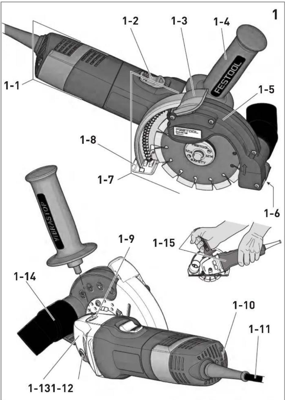
Head of Research, Development and Technical Documentation
Wendlingen, 2017-05-15
natural_image
Five black circular icons representing different workplace safety symbols: helmet, glasses, headphones, hand, and boots (no text or labels)Trennen a h = 4,0 m/s^2
$$ K = 1, 5 \mathrm{m} / \mathrm{s} ^ {2} $$
natural_image
Technical illustration of a mechanical component with cross-sectional views (no text or symbols)Original operating manual
1 S y m b o
Symbol Significance

Warning of general danger

Risk of electric shock

Read operating instructions and safety notices!

Wear ear protection.

Wear protective gloves.

Wear a dust mask.

Wear protective goggles.

Wear sturdy footwear!

Disconnect from the power supply!

Do not dispose of as domestic waste.

Tip or advice

Handling instruction

Safety class II

Only place packed cutting disk in Systainer!
2 Safety instructions
2.1 General safety instructions

WARNING! Read all safety warnings, instructions, illustrations and specifications provided with this power tool. Failure to follow all instructions listed below may result in electric shock, fire and/or serious injury.
Save all warnings and instructions for future reference.
The term "power tool" in the warnings refers to your mains-operated (corded) power tool or battery-operated (cordless) power tool.
2.2 Machine-related safety instructions
Safety Warnings Common for Grinding, Sanding, Wire Brushing or Abrasive Cutting-Off Operations:
a. This power tool is intended to fun
grinder, sander, wire brush, or cut-off tool. Read all safety warnings, instructions, illustra-
tions and specifications provided with this power tool. Failure to follow all instructions listed below may result in electric shock, fire and/or serious injury.
b. Operations such as polishing are not recommended to be performed with this power tool. Operations for which the power tool was not designed may create a hazard and cause personal injury.
c. Do not use accessories which are not specifically designed and recommended by the tool manufacturer. Just because the accessory can be attached to your power tool, it does not assure safe operation.
d. The rated speed of the accessory must be at least equal to the maximum speed marked on the power tool. Accessories running faster than their rated speed can break and fly apart.
e. The outside diameter and the thickness of your accessory must be within the capacity rating of your power tool. Incorrectly sized accessories cannot be adequately guarded or controlled.
f. Threaded mounting of accessories must match the grinder spindle thread. For accessories mounted by flanges, the arbour hole of the accessory must fit the locating diameter of the flange. Accessories that do not match the mounting hardware of the power tool will run out of balance, vibrate excessively and may cause loss of control.
g. Do not use a damaged accessory. Before each use inspect the accessory such as abrasive wheels for chips and cracks, backing pad for cracks, tear or excess wear, wire brush for loose or cracked wires. If power tool or accessory is dropped, inspect for damage or install an undamaged accessory. After inspecting and installing an accessory, position yourself and bystanders away from the plane of the rotating accessory and run the power tool at maximum no-load speed for one minute. Damaged accessories will normally break apart during this test time.
h. Wear personal protective equipment. Depending on application, use face shield, safety goggles or safety glasses. As appropriate, wear dust mask, hearing protectors, gloves and workshop apron capable of stopping small abrasive or workpiece fragments. The eye protection must be capable of stopping flying debris generated by various operations. The dust mask or respirator must be capable of filtrating parti-
cles generated by your operation. Prolonged exposure to high intensity noise may cause hearing loss.
i. Keep bystanders a safe distance away from work area. Anyone entering the work area must wear personal protective equipment. Fragments of workpiece or of a broken accessory may fly away and cause injury beyond immediate area of operation.
j. Hold the power tool by insulated gripping surfaces only, when performing an operation where the cutting accessory may contact hidden wiring or its own cord. Cutting accessory contacting a "live" wire may make exposed metal parts of the power tool "live" and could give the operator an electric shock.
k. Position the cord clear of the spinning accessory. If you lose control, the cord may snagged and your hand or arm may be pulled into the spinning accessory.
1. Never lay the power tool down until the accessory has come to a complete stop. The spinning accessory may grab the surface and pull the power tool out of your control.
m.Do not run the power tool while carrying it at your side. Accidental contact with the spinning accessory could snag your clothing, pulling the accessory into your body.
n. Regularly clean the power tool's air vents. The motor's fan will draw the dust inside the housing and excessive accumulation of powdered metal may cause electrical hazards.
o. Do not operate the power tool near flammable materials. Sparks could ignite these materials.
p. Do not use accessories that require liquid coolants. Using water or other liquid coolants may result in electrocution or shock.
Further safety instructions for all operations
Kickback and Related Warnings:
Kickback is a sudden reaction to a pinched or snagged rotating wheel, backing pad, brush or any other accessory. Pinching or snagging causes rapid stalling of the rotating accessory which in turn causes the uncontrolled power tool to be forced in the direction opposite of the accessory's rotation at the point of the binding.
For example, if an abrasive wheel is snagged or pinched by the workpiece, the edge of the wheel that is entering into the pinch point can dig into the surface of the material causing the wheel to climb out or kick out. The wheel may either jump toward or away from the operator, depending on direction of the wheel's movement at the point of pinching. Abrasive wheels may also break under these conditions. Kickback is the result of power tool misuse and/or incorrect operating procedures or conditions and can be avoided by taking proper precautions as given below.
a. Maintain a firm grip on the power tool and position your body and arm to allow you to resist kickback forces. Always use auxiliary handle, if provided, for maximum control over kickback or torque reaction during start-up. The operator can control torque reactions or kickback forces, if proper precautions are taken.
b. Never place your hand near the rotating accessory. Accessory may kickback over your hand.
c. Do not position your body in the area where power tool will move if kickback occurs. Kick-be chatkowill propel the tool in direction opposite to the wheel's movement at the point of snagging.
d. Use special care when working corners, sharp edges etc. Avoid bouncing and snagging the accessory. Corners, sharp edges or bouncing have a tendency to snag the rotating accessory and cause loss of control or kickback.
e. Do not attach a saw chain woodcarving blade or toothed saw blade. Such blades create frequent kickback and loss of control.
Additional safety instructions for grinding and cutting-off operations
Safety Warnings Specific for Grinding and Abrasive Cutting-Off Operations:
a. Use only wheel types that are recommended for your power tool and the specific guard designed for the selected wheel. Wheels for which the power tool was not designed cannot be adequately guarded and are unsafe.
b. The grinding surface of centre depressed wheels must be mounted below the plane of the guard lip. An improperly mounted wheel that projects through the plane of the guard lip cannot be adequately protected.
c. The guard must be securely attached to the power tool and positioned for maximum safety, so the least amount of wheel is exposed towards the operator. The guard helps to protect the operator from broken wheel fragments, accidental contact with wheel and sparks that could ignite clothing.
d. Wheels must be used only for recommended applications. For example: do not grind with the side of cut-off wheel. Abrasive cut-off wheels are intended for peripheral grinding, side forces
applied to these wheels may cause them to shatter.
e. Always use undamaged wheel flanges that are of correct size and shape for your selected wheel. Proper wheel flanges support the wheel thus reducing the possibility of wheel breakage. Flanges for cut-off wheels may be different from grinding wheel flanges.
f. Do not use worn down wheels from larger power tools. Wheel intended for larger power tool is not suitable for the higher speed of a smaller tool and may burst.
Additional safety instructions for cutting-off operations
Additional Safety Warnings Specific for Abrasive Cutting-Off Operations:
a. Do not "jam" the cut-off wheel or apply excessive pressure. Do not attempt to make an excessive depth of cut. Overstressing the wheel increases the loading and susceptibility to twisting or binding of the wheel in the cut and the possibility of kickback or wheel breakage.
b. Do not position your body in line with and behind the rotating wheel. When the wheel, at the point of operation, is moving away from your body, the possible kickback may propel the spinning wheel and the power tool directly at you.
c. When wheel is binding or when interrupting a cut for any reason, switch off the power tool and hold the power tool motionless until the wheel comes to a complete stop. Never attempt to remove the cut-off wheel from the cut while the wheel is in motion otherwise kickback may occur. Investigate and take corrective action to eliminate the cause of wheel binding.
d. Do not restart the cutting operation in the workpiece. Let the wheel reach full speed and carefully re-enter the cut. The wheel may bind, walk up or kickback if the power tool is restarted in the workpiece.
e. Support panels or any oversized workpiece to minimize the risk of wheel pinching and kick-back. Large workpieces tend to sag under their own weight. Supports must be placed under the workpiece near the line of cut and near the edge of the workpiece on both sides of the wheel.
f. Use extra caution when making a "pocket cut" into existing walls or other blind areas. The protruding wheel may cut gas or water pipes, electrical wiring or objects that can cause kickback.
Additional safety instructions for wire brushing operations
Safety Warnings Specific for Wire Brushing Operations:
a. Be aware that wire bristles are thrown by the brush even during ordinary operation. Do not overstress the wires by applying excessive load to the brush. The wire bristles can easily penetrate light clothing and/or skin.
b. If the use of a guard is recommended for wire brushing, do not allow any interference of the wire wheel or brush with the guard. Wire wheel or brush may expand in diameter due to work load and centrifugal forces.
Further safety information
- The power tool is not permitted for operation in damp and wet environments, if it is raining or snowing or there is fog, and in an explosive environment.
- Only use the approved extension cable and cable connections for outdoor applications.
- Do not carry the power tool by the cable.
- Only insert the connector of the connection cable in the socket when the power tool is switched off.
- Always remove the mains plug from the socket before you replace the cutting disc or perform other settings at the power tool.
- Only guide the power tool into the material when it is switched on (running).
- For safety reasons, the workpiece must be clamped in a vice or other clamping device. A clamped workpiece frees up both hands for operating the power tool.
- Cutting or grinding stone or masonry is only permitted with the use of a guide block.
- Do not work on ladders.
- People under 16 years of age are prohibited from working with the power tool.
- Do not use quick clamping nuts for clamping the cutting disc.
- During the installation ensure that the direction of rotation marked on the label and/or the diamond tool by the arrow corresponds to the direction of rotation of the power tool used.
- The flange and the safety clamping nut must be tightened to a minimum tightening torque of 20 Nm.
- Use suitable tools with corresponding specifications for the materials being processed - see information on the diamond disc and the packaging.
- Avoid mechanical damage to the diamond tool, whether it is caused by force, impact or heat.
- Guide the diamond disc vertically into the section.
- Always work with an oscillating movement, so that the disc can cool and to avoid the diamond disc overloading.
- Allow the equipment to cool after several cuts or intensive cutting, in order to avoid the diamond tool overheating.
- Do not use the diamond cutting disc for sanding. Do not exert any lateral pressure on the diamond cutting disc.
- Diamond tools are self-sharpening. Reduced cutting performance and a circular fiery edge indicate a blunt diamond tool. The tool can be sharpened by making short cuts in an abrasive material (sand-lime brick, asphalt or aerated concrete). Sporadic sparks typically occur when cutting stone. They are therefore not critical.
- Only operate the power tool with a mounted extraction hood and additional handle, unless otherwise specified.
- Do not cut metal objects, nails or screws.

natural_image
Five black circular icons representing different workplace safety symbols: mask, helmet, hand, and boot (no text or labels)- Wear suitable protective equipment such as ear protection, safety goggles, a dust mask for work which generates dust, protective gloves when working with raw materials and when changing tools, and sturdy footwear.
- Use suitable detectors to determine if utility lines are hidden in the work area or call the local utility company for assistance. Contact with electric lines can lead to fire and electric shock. Damaging a gas line can lead to explosion. Penetrating a water line causes property damage or may cause an electric shock.
- Hazardous or toxic dust may arise when working (e.g. paint products which contain lead, some types of wood, etc.). Materials containing asbestos can only be processed by qualified individuals. Contact with or inhalation of this dust may pose a risk for the operating personnel or individuals in the vicinity. Observe the safety regulations applicable in your country.

Wear a P2 respiratory mask to protect your health and use a suitable extractor.
2.3 Emission levels
Levels determined in accordance with EN 60745 are typically:
Sound pressure level L _PA = 90 dB(A)
Noise level L W_A = 101 dB(A)
Measuring uncertainty allowance K = 3 dB

CAUTION
Operating noise
Damage to hearing
▶ Use ear protection!
Vibration emission value a_h (vector sum for three directions) and uncertainty K measured in accordance with EN 60745:
Vibration emission level (3-axles)
Cutting a h = 4,0 m/s^2 K = 1,5 m/s^2
The specified emission values (vibration, noise)
- are used to compare machines.
- They are also used for making preliminary estimates regarding vibration and noise loads during operation.
- They represent the primary applications of the power tool.
Increase possible for other applications, with other insertion tools or if not maintained adequately. Take note of idling and downtimes of machine!
3 Intended use
Consisting of an angle grinder and extraction hood, the Dia cutting system is designed for grooving and cutting into concrete or stone materials and tiles without the use of water.
The extraction hood can only be operated with original Festool or Protocol angle grinders D 125.

The user is liable for improper or non-in-tended use.
4 T e c h n i
Dia cutting system DSC-AG 125 FH
Extraction hood DCC-AG 125 FH
| Tool diameter 125 mm | |
| Disc thickness max. 6,5 mm | |
| Cutting depth | 27 mm |
| Extractor hose diameter | 27/36 mm |
| Weight | 0,6 kg |
Angle grinders AG 125-14 DE
| Power supply 220 - 240 V ~ | |
| Mains frequency 50/60 Hz | |
| Power consumption 1400 W | |
| No-load speed 3500 - 11000 | min-1 |
| Circumferential speed 80 m/s | |
| Grinding spindle thread M 14 | |
| Weight 2,3 kg | |
| Safety class | ☐/II |
5 Machine features
| [1-1] | Angle grinders |
| [1-2] | On/Off switch |
| [1-3] | Pull-back arm |
| [1-4] | Additional handle |
| [1-5] | Pendulum hood |
| [1-6] | Cut indicator |
| [1-7] | Extraction hood |
| [1-8] | Guide table |
| [1-9] | Thread for additional handle |
| [1-10] | Speed control |
| [1-11] | Mains power cable |
| [1-12] | Spindle lock |
| [1-13] | Transmission housing |
| [1-14] | Extractor connector |
| [1-15] | Insulated gripping surfaces (grey shaded area) |
Accessories shown or described are sometimes not included in the scope of delivery.
The specified illustrations appear at the beginning of the Operating Instructions.
6 Settings


WARNING
Risk of injury, electric shock
▶ Always pull the mains plug out of the socket before performing any type of work on the machine!
6.1 Auxiliary handle

Always use an additional handle, in order to guarantee safe and fatigue-free working po-, unless otherwise specified.
With help of the special "VIBRASTOP" feature, the vibrations are reduced by the additional handle[1-4].
▶ Screw in additional handle [1-4] at the thread[1-9].
6.2 Electronics
Smooth start-up
The electronically controlled smooth start-up prevents kickbacks. A fuse with 16 A is sufficient thanks to the restricted start-up current.
Speed control
You can regulate the speed steplessly within the speed range using the adjusting wheel [1-10] (see Technical data). This enables you to optimise the speed to suit the respective material. Please also note the specifications on the tools.
Kickback protection
In the event of sudden speed reduction, for example as a result of a blockage in the cut, the power supply in the motor is interrupted. Following recommissioning, first of all the machine must be switched off and then switched back on again.
Restart protection
The integral restart protection prevents the machine from automatically starting up again after an interruption in power when the machine is used in continuous operating mode. In this case the machine must be switched off and then switched back on again.
Constant speed
The preselected motor speed is maintained on a constant level. Electronic controls ensure a steady cutting speed even when operating under different loads.
Overload protection dependent on the temperature
To protect against overheating, the safety electronics switch to cooling mode when a critical temperature is reached. The motor continues to run and the constant speed is deactivated. After a cooling time of approx. 10-20 seconds, the machine can be operated again at full load.
6.3 Dust extraction

WARNING
Dust hazard
▶ Always work with a dust extractor.
▶ Always observe country-specific regulations.
In order to ensure functional extraction, connect a Festool mobile dust extractor of class M or H and with minimum suction power of 3900 l/min and vacuum of 24,000 Pa, at the extractor connector[1-14].
Note: Always work with a connected dust extractor. Only use dust extractors with anti-static design, in order to avoid static discharges.
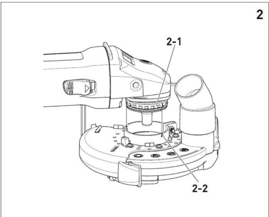
7 Mount extraction hood

WARNING! Never use an angle grinder without an extraction hood!
Upon purchase of the extraction hood as an accessory, you have to mount this at the angle grinder AG 125 or AGP 125, as described below:
▶ Remove cutting disc, see chapter 8.
▶ Insert clamping collar of the angle grinder[2-1] in the clamp. Insert guide pins[2-2] in the grooves at the clamping collar of the angle grinder[2].
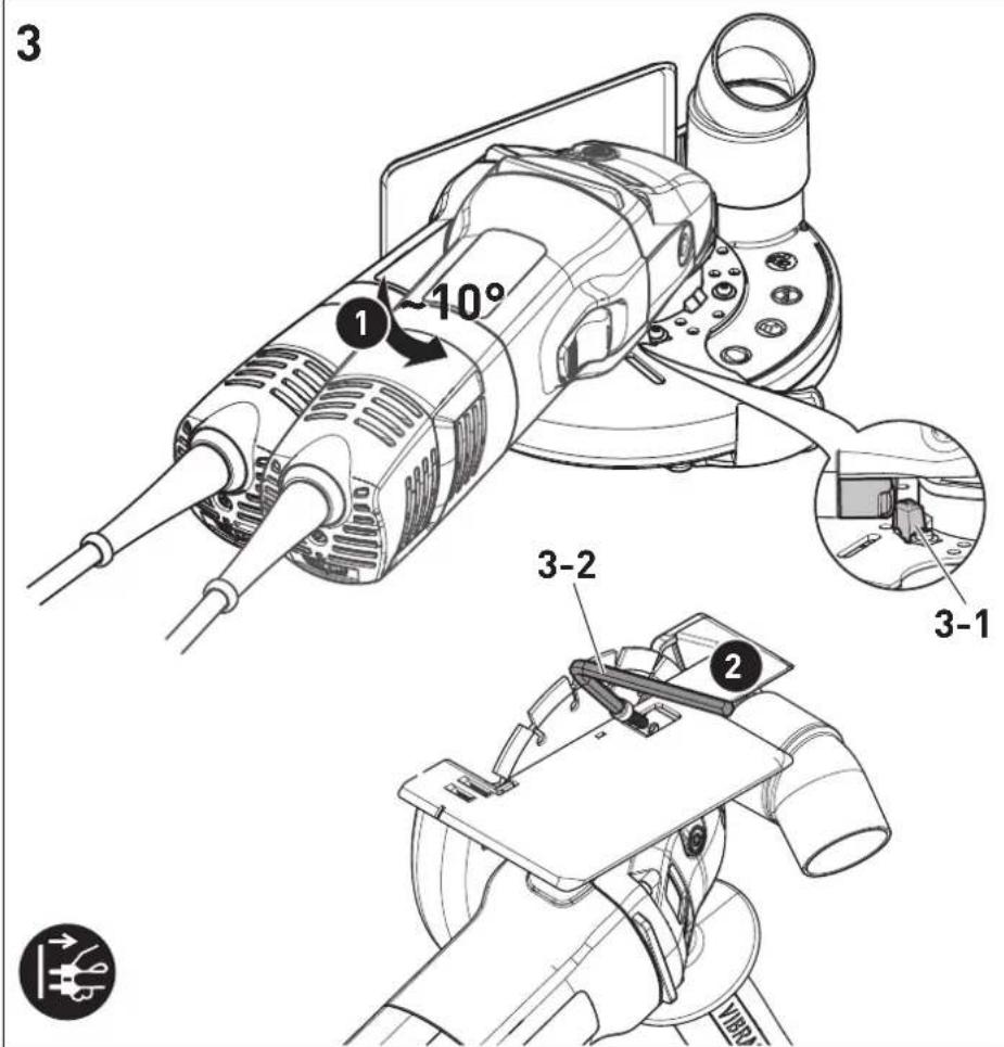
▶ Turn the angle grinder counter-clockwise as far as the stop (approx. 10^ ), [3] until it touches the stop[3-1].
▶ Screw clamp tightly to the screw using the hexagonal spanner supplied [3-2]. Ensure correct vertical position of the bearing cap of the angle grinder in the clamp.
Removal in reverse order.
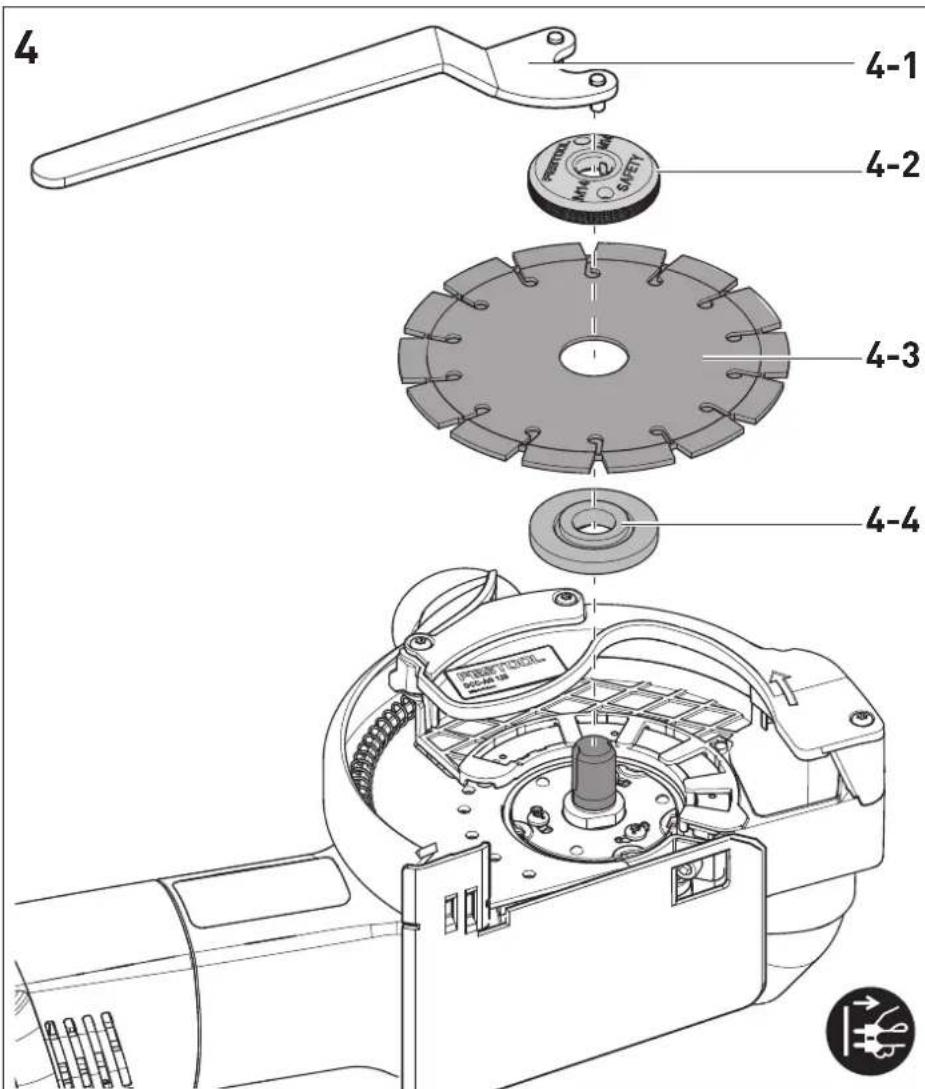
8 Replace diamond cutting disc

WARNING
Risk of accident and injury
▶ Do not use any other safety clamping nuts than the one supplied. Do not use quick clamping nuts!
▶ Only use cutting discs recommended by the manufacturer and flanges which are part of the items included with the sander.

CAUTION
Hot and sharp tools
Risk of injury
▶ Do not use insert tools that are blunt or defective.
▶ Wear protective gloves.
Only use undamaged safety clamping nuts!
natural_image
Diagram of a car wheel with cross-sectional views showing internal components (no text or labels)- Bonding material cutting discs cannot be used!
- The permissible circumferential speed of the discs must be 80 m/s.
- Allow new cutting discs to run for approximately one minute without load as a trial.
- Vibrating discs cannot be used.
- Protect the discs against impacts and grease.
- If the grinding and cutting discs are worn, it is recommended to replace these with new ones. This way the optimal grinding or cutting power of the device (circumferential speed of the grinding and cutting discs) is maintained.
▶ Clean the flange [4-4] and safety clamping nut[4-2], as well as the cutting disc surfaces[4-3].
▶ Position flange [4-4] with the attachment at the spindle of the angle grinder.
▶ Position cutting disk [4-3].

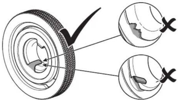
Pay attention to the prescribed direction of rotation (arrow on the cutting disk = arrow on the device).
The flange attachment must fit precisely in the disc opening.
▶ Position the safety clamping nut [4-2] on the cutting disc, press the spindle lock [1-12] and tighten the safety clamping nut using the wrench[4-1].

Before switching on, check whether the cutting disc and the pendulum hood [1-5] move freely.
Removal in reverse order.
9 Commissioning

WARNING
Unauthorised voltage or frequency!
Risk of accident
The mains voltage and the frequency of the power source must correspond with the specifications on the machine's name plate.
▶ In North America, only Festool machines with the voltage specifications 120 V/60 Hz may be used.
9.1 Switch on/off
Switching on
▶ Move the ON/OFF switch [1-2] forwards.
▶ Continuous operation: Pressing the front part of the switch at the same time locks the ON/OFF switch.
The electric power tool starts.
Only make contact with the material once the machine has reached operating speed.
Switching off
▶ Lift the power tool from the processed material.
▶ Release the ON/OFF switch[1-2].
▶ During continuous operation: Press the rear part of the ON/OFF switch[1-2].

WARNING
Rebound, ejected parts
Risk of injury
▶ Before setting down the machine, wait until the rotating tool has come to a complete stop.
9.2 Insulated gripping surfaces
The power tool must be held using two hands at the insulated gripping surfaces[1-15]: One hand at the motor housing behind the switch and one hand at the additional handle[1-4].
If the additional handle is removed for cuts close to the edge, the left hand must hold the power tool at the pull-back arm[1-3].
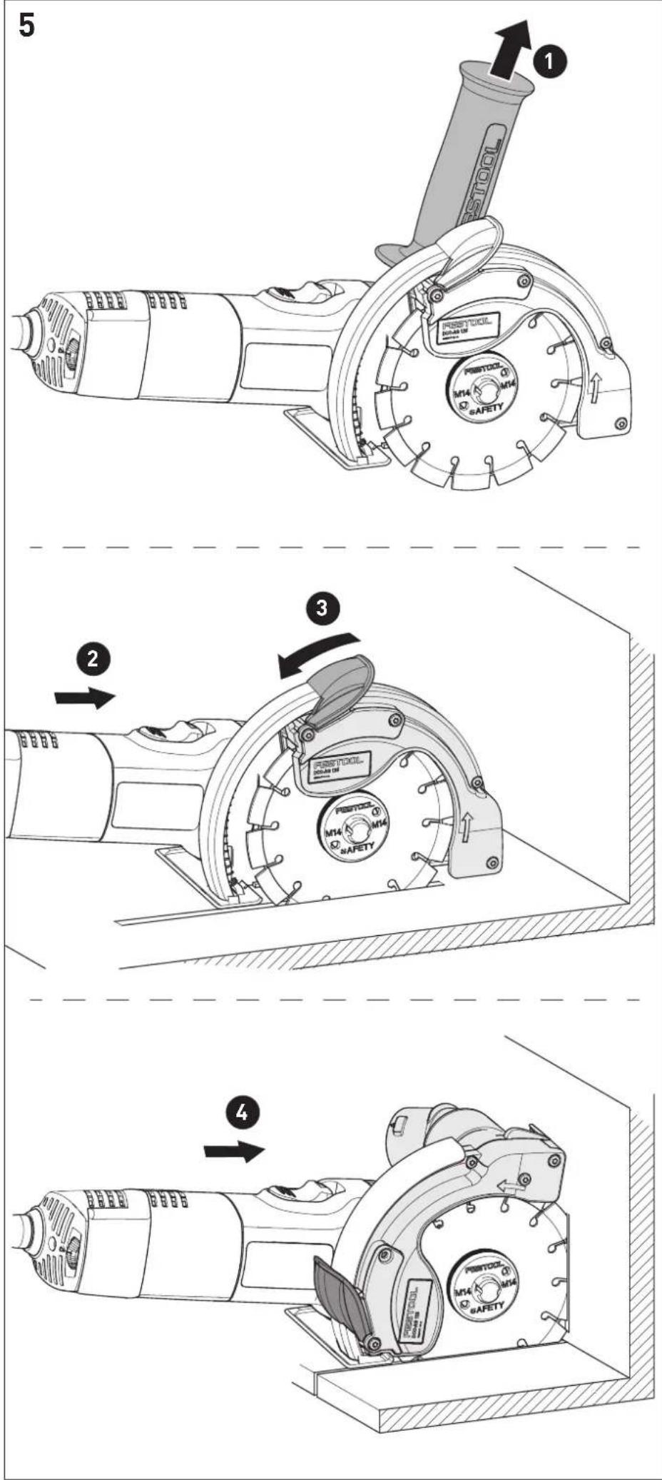
9.3 Cuts close to the edge [5]
![FESTOOL DSCAG 125 FH - Cuts close to the edge [5] - 1](/content/2026/03/557309/images/dbeb043f0e76f78e22e5426add63683c4882040902c1c9096469bb8e6bd45713.jpg)
WARNING! With the exception of cuts close to the edge, the extraction hood can only be used with the locked pendulum hood and the additional handle.
▶ Remove additional handle.
▶ Check whether the pendulum hood can move freely with the pull-back arm and automatically returns to the starting position.
▶ Hold the power tool using the right hand.
▶ Shortly before the wall unlock the pull-back arm of the extraction hood using the left hand.
▶ Pull back the pendulum hood using the pullback arm and, at the same time, continue cutting to get as close to the wall as possible.
The maximum function of the dust extraction is thus guaranteed.
▶ After the cutting process, bring the pendulum hood back to the starting position with the pull-back arm.
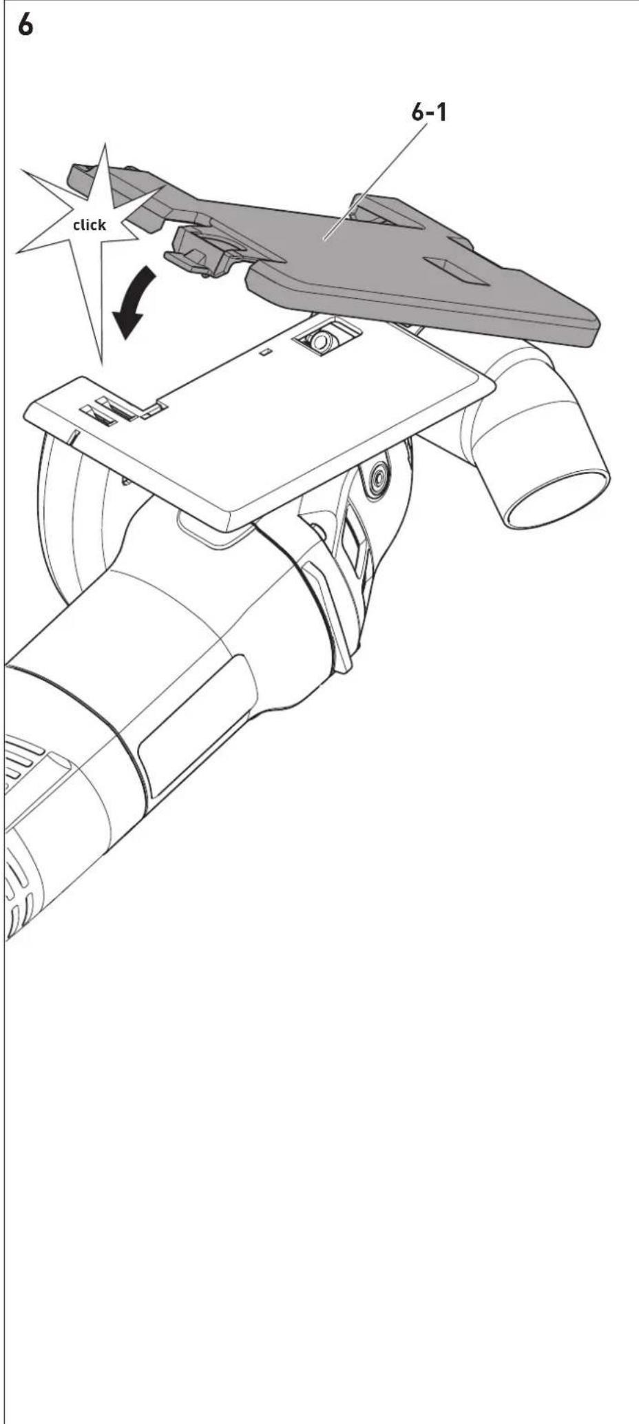
9.4 Tabletop
The tabletop [6-1] reduces the risk of surface damage to the workpiece. Push the tabletop to the front edge of the guide table of the extraction hood and lock into place.
10 Accessories

WARNING
Risk of injury
▶ Always pull the mains plug out of the socket before performing work on the machine such as changing and adjusting accessories!
Always use original Festool tools and accessories.
Using low-quality tools or accessories from other manufacturers may increase the risk of injury and cause serious machine imbalance that decreases the quality of the working results and accelerates machine wear.
The order numbers of the accessories and tools can be found in the Festool catalogue or on the Internet under "www.festool.com".
11 Service and maintenance

WARNING
Risk of injury, electric shock
▶ Always disconnect the mains plug from the socket before performing maintenance work on the machine!
▶ All maintenance and repair work which requires the motor housing to be opened must only be carried out by an authorised service workshop.

Customer service and repair only through manufacturer or service workshops: Please find the nearest address at: www.festool.com/service
Only use original Festool spare parts! Order No. at: www.festool.com/service

Regular cleaning of the machine, above all the adjustment devices and the guides, is an important safety factor.
- The packed machine can be stored in a dry location without heating, if the internal temperature does not fall below -5 °C. The unpacked machine
can only be stored in an enclosed, dry room, where the temperature does not fall below +5 °C and where no strong temperature fluctuations may occur.
- To ensure constant air circulation, always keep the cooling air openings in the motor housing clean and free of blockages.
- The machine automatically shuts down if the carbon brushes are worn. The machine must be sent to the bodyshop for maintenance.
- If the pendulum hood [1-5] does not automatically return to the starting position, clean the pendulum hood by repeated opening and closing. If the fault cannot be eliminated, hand over the machine to Customer Service.
- Check the plug and the cable regularly and should either become damaged, in order to avoid a hazard, have them replaced by an authorised after-sales service workshop.
12 Environment
Do not dispose of electric power tools in household waste! Recycle devices, accessories and packaging. Observe applicable country-specific regulations.
EU only: In accordance with European Directive on waste electrical and electronic equipment and implementation in national law, used electric power tools must be collected separately and handed in for environmentally friendly recycling.
Information on REACH: www.festool.com/reach
natural_image
Diagram of a car tire with cross-sectional views showing internal components (no text or labels)natural_image
Five black circular icons representing different workplace safety symbols: mask, helmet, hand, shoe, and boots (no text or labels)natural_image
Diagram of a car wheel with cross-sectional views showing internal components (no text or labels)natural_image
Diagram of a mechanical component with cross-sectional views showing internal structure (no text or labels)natural_image
Five black circular icons representing different workplace safety symbols: mask, helmet, hand, boot, and gear (no text or labels)natural_image
Diagram of a tire cross-section showing internal components and two close-up views (no text or labels)natural_image
Diagram of a mechanical component with cross-sectional views showing internal structure (no text or labels)natural_image
Diagram of a mechanical component with cross-sectional views showing internal structure (no text or labels)natural_image
Diagram of a mechanical component with cross-sectional views showing internal structure (no text or labels)natural_image
Diagram of a car tire with cross-sectional views showing internal components (no text or labels)- Ikke bruk kappeskiver med bindemiddel!
- Tillatt omkretshastighet for skivene skal være på 80 m/s.
- Prøvekjør nye kappeskiver i ca. ett minutt uten
belastning.
natural_image
Diagram of a car tire with cross-sectional views showing internal components (no text or labels)natural_image
Diagram of a mechanical component with cross-sectional views showing internal structure (no text or labels)natural_image
Diagram of a mechanical component with cross-sectional views showing internal structure (no text or labels)natural_image
Diagram of a car tire with cross-sectional views showing internal components (no text or labels)Declaration of Conformity
We as the manufacturer Festool GmbH, Wertstraße 20, 73240 Wendlingen, Germany declare under our sole responsibility that the product(s):
Designation:
Designation of Type(s):
Serial number(s) 1):
Angle grinder
DSC-AG 125, DSC-AG 125 FH
201807
fulfills all the relevant provisions of the following UK Regulations:
S.I. 2008/1597
S.I. 2016/1091
S.I. 2012/3032
Supply of Machinery (Safety) Regulations 2008
Electromagnetic Compatibility Regulations 2016
Restriction of the Use of Certain Hazardous Substances in Electrical and Electronic Equipment Regulations 2012
and are manufactured in accordance with the following designated standards:
• BS EN 60745-1:2009 + A11:2010
• BS EN 60745-2-3:2011+A13:2015
• BS EN 55014-1:2017
• BS EN 55014-2:2015
• BS EN IEC 61000-3-2:2019
• BS EN 61000-3-3:2013
• BS EN IEC 63000:2018
1) in the specified serial number range (S-Nr.) from 400000000 - 499999999

Place and date of declaration: Wendlingen, 15.04.2021
Signed on behalf of and in name of Festool GmbH

Markus Stark
Head of Productdevelopment
i.v. Q Brandt
Ralf Brandt
Head of Productconformity