DSCAG 125 PlusFS - Slicer FESTOOL - Free user manual and instructions
Find the device manual for free DSCAG 125 PlusFS FESTOOL in PDF.

| Brand | Festool |
| Model | DSCAG 125 PlusFS |
| Category | Cutter (diamond cutting system) |
| Tool diameter | 125 mm |
| Disc thickness (with blade) | max. 3 mm |
| Disc thickness (without blade) | max. 6.5 mm |
| Cutting depth (without rail) | 27 mm |
| Suction hose diameter | 27/36 mm |
| Total weight (hood + grinder) | approx. 4.5 kg |
| Power supply | 220-240 V~, 50/60 Hz |
| Power consumption | 1400 W |
| No-load speed | 3500 - 11000 min⁻¹ |
| Max. circumferential speed | 80 m/s |
| Spindle thread | M 14 |
| Main functions | Grooving and cutting concrete/stone without water |
| Onboard electronics | Starting current limitation, speed regulation, thermal protection, restart protection |
| Assembly | Adjustable suction hood, additional handle VIBRASTOP |
| Suction | Connection for Festool class L/M/H vacuum cleaner, anti-static hose recommended |
| Safety | Double insulation, kickback stop, restart protection, protective hood mandatory |
| Maintenance | Self-disconnecting brushes, cleaning of cooling slots, repair by authorized service center |
| Spare parts | Use only original Festool parts |
| Sound level | 90 dB(A) (intensity), 101 dB(A) (noise level) |
| Vibration | a_h = 4.0 m/s² (K=1.5 m/s²) |
Frequently Asked Questions - DSCAG 125 PlusFS FESTOOL
User questions about DSCAG 125 PlusFS FESTOOL
0 question about this device. Answer the ones you know or ask your own.
Ask a new question about this device
Download the instructions for your Slicer in PDF format for free! Find your manual DSCAG 125 PlusFS - FESTOOL and take your electronic device back in hand. On this page are published all the documents necessary for the use of your device. DSCAG 125 PlusFS by FESTOOL.
USER MANUAL DSCAG 125 PlusFS FESTOOL
GB Original operating manual - Dia cutting system 17
natural_image
Black and white photo of a mechanical device with no visible text or symbols1
3
4
natural_image
Diagram of a drill presser with two electric drill heads and a TBRASOP device, showing rotational motion (no text or symbols)4a
natural_image
Technical line drawing of a vehicle chassis frame with no visible text or symbols5
natural_image
Technical line drawing of a mechanical assembly with gears and levers (no text or symbols)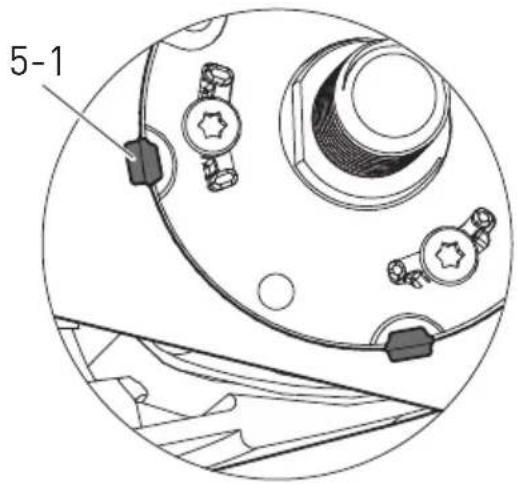
6
natural_image
Line drawing of a helicopter with visible propellers and control points (no text or symbols)Wolfgang Zondler Head of Research, Development and Technical Documentation
Wendlingen, 2017-05-15
Dia cutting system DSC-AG 125
1 Technical data
Exhaust Cover DCC-AG 125
| Tool∅ | 125 |
| Disc thickness | |
| with a bar max. 3 mm | |
| without a bar max. 6.5 mm | |
| Cut depth (without a guide bar) 27 mm | |
| Exhaust hose∅ | 27/36 |
| Weight | 2.2 |
Angular grinder AG 125-14 DE
| Voltage 220-240 V~ | |
| Frequency 50/60 Hz | |
| Input | 1400 W |
| Idle revolutions | 3500 - 11000 min ^-1 |
| Peripheral velocity | 80 m/s |
| Grinding spindle thread | M 14 |
| Limits to interaction current | ● |
| Constant electronics | ● |
| Heat protection | ● |
| Weight | 2,3 |
| Protection level | II /回 |
2 Symbols

Double insulation

Warning of general danger

Risk of electric shock

Use protective goggles!

Wear ear protection!

Read the instructions

Not to be included in municipal refuse
i Advice or tip
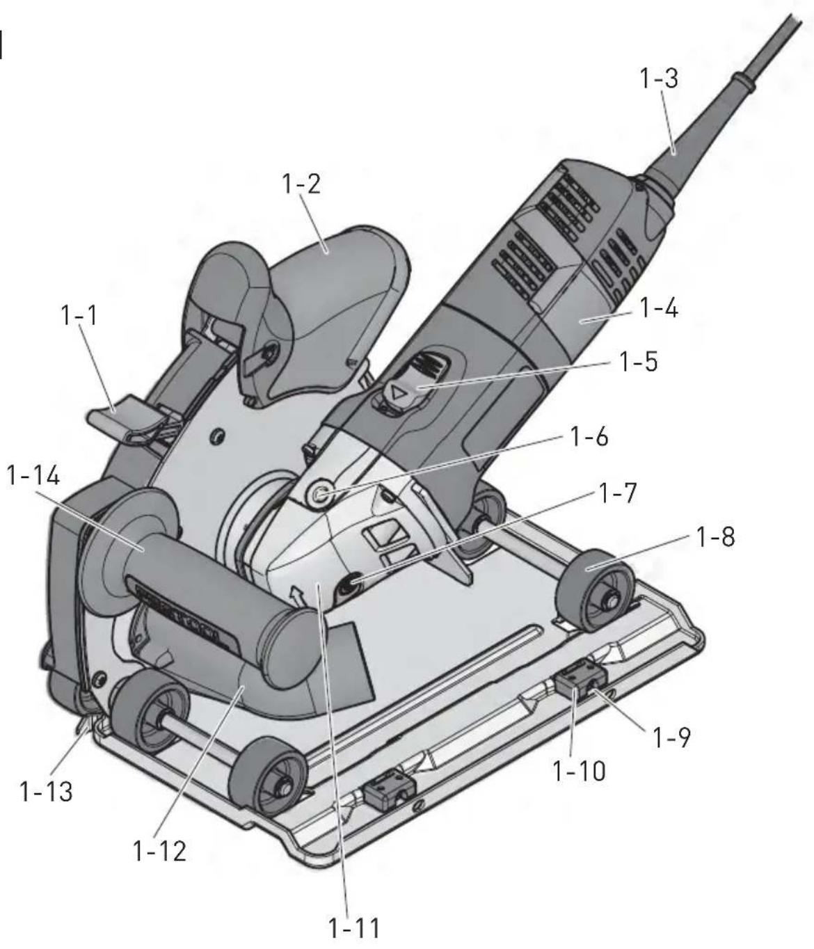
3 Control elements
[1-1] Arresting button
[1-2] Exhaust Cover
[1-3] Power cable
[1-4] Angular grinder
[1-5] Switch
[1-6] Threading for clamping and additional handle
[1-7] Spindle locking plunger
[1-8] Rollers
[1-9] Screw for setting bar clearance
[1-10] Bar guide
[1-11] Gear box
[1-12] Bar guide
[1-13] Cut indicator
[1-14] Additional handle kg
[1-15] Speed control
Accessories that are illustrated or described here are not always included in the scope of delivery.
The specified illustrations can be found at the beginning of the operating instructions.
4 Intended use
Consisting of an angle grinder and extraction hood, the Dia cutting system is designed for grooving and cutting into concrete or stone materials without the use of water.
The user proper is responsible for improper usage.
5 Notes on Safety Prevention
5.1 General safety instructions

WARNING! Read all safety warnings, instructions, illustrations and specifications provided with this power tool. Failure
to follow all instructions listed below may result in electric shock, fire and/or serious injury.
Save all warnings and instructions for future reference.
The term „power tool“ in the warnings refers to your mains-operated (corded) power tool or battery-operated (cordless) power tool.
5.2 Safety instructions for all operations
General safety instructions for grinding, abrasive cutting and wire brushing:
a) This power tool is intended to function as grinding, sanding with sandpaper, wire brushing and abrasive cutting. Read all safety warnings, instructions, illustrations and specifications provided with this power tool. Failure to follow all instructions listed below may result in electric shock, fire and/or serious injury.
b) Operations such as polishing is not recommended to be performed with this power tool. Operations for which the power tool was not
designed may create a hazard and cause personal injury.
c) Do not use accessories which are not specifically designed and recommended by the tool manufacturer. Just because the accessory can be attached to your power tool, it does not assure safe operation.
d) The rated speed of the accessory must be at least equal to the maximum speed marked on the power tool. Accessories running faster than their rated speed can break and fly apart.
e) The outside diameter and the thickness of your accessory must be within the capacity rating of your power tool. Incorrectly sized accessories cannot be adequately guarded or controlled.
f) The arbour size of wheels, fl anges, backing pads or any other accessory must properly fit the spindle of the power tool. Accessories with arbour holes that do not match the mounting hardware of the power tool will run out of balance, vibrate excessively and may cause loss of control.
g) Do not use a damaged accessory. Before each use inspect the accessory such as ABRASIV wheels for chips and cracks, backing pad for cracks, tear or excess wear, wire brush for loose or cracked wires. If power tool or accessory is dropped, inspect for damage or install an undamaged accessory. After inspecting and installing an accessory, position yourself and bystanders away from the plane of the rotating accessory and run the power tool at maximum no-load speed for one minute. Damaged accessories will normally break apart during this test time.
h) Wear personal protective equipment. Depending on application, use face shield, safety goggles or safety glasses. As appropriate, wear dust mask, hearing protectors, gloves and workshop apron capable of stopping small ABRASIV or workpiece fragments. The eye protection must be capable of stopping fl ying debris generated by various operations. The dust mask or respirator must be capable of filtrating particles generated by your operation. Prolonged exposure to high intensity noise may cause hearing loss.
i) Keep bystanders a safe distance away from work area. Anyone entering the work area must wear personal protective equipment. Fragments of workpiece or of a broken accessory may fly away and cause injury beyond im-
mediate area of operation.
j) Hold power tool by insulated gripping surfaces only, when performing an operation where the cutting accessory may contact hidden wiring or its own cord. Cutting accessory contacting a "live" wire may make exposed metal parts of the power tool "live" and shock the operator.
k) Position the cord clear of the spinning accessory. If you lose control, the cord may be cut or snagged and your hand or arm may be pulled into the spinning accessory.
1) Never lay the power tool down until the accessory has come to a complete stop. The spinning accessory may grab the surface and pull the power tool out of your control.
m) Do not run the power tool while carrying it at your side. Accidental contact with the spinning accessory could snag your clothing, pulling the accessory into your body.
n) Regularly clean the power tool's air vents. The motor's fan will draw the dust inside the housing and excessive accumulation of powdered metal may cause electrical hazards.
o) Do not operate the power tool near fl ammable materials. Sparks could ignite these materials.
p) Do not use accessories that require liquid coolants. Using water or other liquid coolants may result in electrocution or shock.
Further safety instructions for all operations
Kickback and Related Warnings
Kickback is a sudden reaction to a pinched or snagged rotating wheel, backing pad, brush or any other accessory. Pinching or snagging causes rapid stalling of the rotating accessory which in turn causes the uncontrolled power tool to be forced in the direction opposite of the accessory's rotation at the point of the binding.
For example, if an ABRASIV wheel is snagged or pinched by the workpiece, the edge of the wheel that is entering into the pinch point can dig into the surface of the material causing the wheel to climb out or kick out. The wheel may either jump toward or away from the operator, depending on direction of the wheel's movement at the point of pinching. ABRASIV wheels may also break under these conditions.
Kickback is the result of power tool misuse and/or incorrect operating procedures or conditions and can be avoided by taking proper precautions as given below.
a) Maintain a firm grip on the power tool and position your body and arm to allow you to
resist kickback forces. Always use auxiliary handle, if provided, for maximum control over kickback or torque reaction during start-up. The operator can control torque reactions or kickback forces, if proper precautions are taken.
b) Never place your hand near the rotating accessory. Accessory may kickback over your hand.
c) Do not position your body in the area where power tool will move if kickback occurs. Kickback will propel the tool in direction opposite to the wheel's movement at the point of snagging.
d) Use special care when working corners, sharp edges etc. Avoid bouncing and snagging the accessory. Corners, sharp edges or bouncing have a tendency to snag the rotating accessory and cause loss of control or kickback.
e) Do not attach a saw chain woodcarving blade or toothed saw blade. Such blades create frequent kickback and loss of control.
Additional safety instructions for grinding and cutting
Safety Warnings Specific for Grinding and ABRASIV Cutting-Off Operations:
a) Use only wheel types that are recommended for your power tool and the specific guard designed for the selected wheel. Wheels for which the power tool was not designed cannot be adequately guarded and are unsafe.
b) The guard must be securely attached to the power tool and positioned for maximum safety, so the least amount of wheel is exposed towards the operator. The guard helps to protect operator from broken wheel fragments and accidental contact with wheel.
c) Wheels must be used only for recommended applications. For example: do not grind with the side of cut-off wheel. ABRASIV cut-off wheels are intended for peripheral grinding, side forces applied to these wheels may cause them to shatter.
d) Always use undamaged wheel fl anges that are of correct size and shape for your selected wheel. Proper wheel fl anges support the wheel thus reducing the possibility of wheel breakage. Flanges for cut-off wheels may be different from grinding wheel fl anges.
e) Do not use worn down wheels from larger power tools. Wheel intended for larger power tool is not suitable for the higher speed of a smaller tool and may burst.
Additional safety instructions for abrasive cutting
Other special safety instructions for abrasive cutting:
a) Prevent the cutting disc from seizing and do not apply excessive pressure. Never make excessively deep cuts. Overloading the cutting disc increases the stress placed on the disc, susceptibility to tilting or seizing and the possibility of kickback or disc breakage.
b) Avoid the area in front of and behind the rotating cutting disc. If you move the cutting disc in the workpiece away from the body, the electric power tool may kick back, throwing the rotating disc directly towards you.
c) If the cutting disc seizes or you intend to take a break from work, switch off the machine and hold still until the disc comes to a complete stop. Never attempt to remove the rotating cutting disc from the cut, otherwise the machine may kick back. Identify and rectify the cause of the seizure.
d) Do not switch the electric power tool on again while the disc is still embedded in the workpiece. Allow the cutting disc to reach full speed before carefully continuing with the cut. Otherwise the disc may seize, jump out of the workpiece or cause a kickback.
e) Always support panels or large workpieces to minimise the risk of a kickback caused by a seized cutting disc. Large workpieces may sag under their own weight. The workpiece must be supported either side of the disc, both near the cut and along the edge.
f) Proceed with particular caution when making „pocket cuts“ in existing walls or other invisible areas. A cutting disc plunged into a wall may cut into gas or water pipes, electric cables or other objects and cause the machine to kick back.
Additional safety instructions for wire brushing operations
Safety Warnings Specific for Wire Brushing Operations:
a) Be aware that wire bristles are thrown by the brush even during ordinary operation. Do not overstress the wires by applying excessive load to the brush. The wire bristles can easily penetrate light clothing and/or skin.
b) If the use of a guard is recommended for wire brushing, do not allow any interference of the wire wheel or brush with the guard. Wire wheel
or brush may expand in diameter due to work load and centrifugal forces.
Further safety instructions
-The machine may not be used in damp and wet spaces, outdoor when it is rainy, foggy or snowy or in the explosive environment.
-Before use always inspect the fl exible lead and the plug. Have the defects repaired by a specialist repair shop.
-Outside the premise use only approved extension leads and cable connections.
- Apply the machine to the material only when switched on.
-Do not carry the machine by the lead.
-Do not work on a ladder.
-When operating the tool, use protective gloves and tough footwear.
-When operating the tool, use goggles and ear protectors.
-The dust generated during work is harmful to health. When operating the tool, use the dust extraction system and the respirator.
-Materials containing asbestos can only be processed by qualified individuals. Comply with the safety regulations that apply in your country.
-Flexible power supply cable always route from the tool backwards.
-Only use milling rings recommended by the manufacturer.
-The machine is only allowed be used when protective guard is in place and additional handle is fastened.
- Plug in the flexible power supply cable's plug into the wall socket when the machine is off.
-Make yourself sure whether the material that is going to be machined does not contain electric, water or gas lines – an injury could occur.
-Do not mill over metal objects, nails or screws.
-The machine is not allowed to be operated by a person under 16 years of age.
- Only for AS/NZS: The tool shall always be supplied via residual current device with a rated residual current of 30 mA or less.
-Do not use quick-change nuts for clamping the disc.
-When clamping, be careful about the direction of rotation marked on the label and/or the diamond tool, which must be the same as the direction of the actual rotation of the machine used.
-The fl ange and fastening nuts must be properly tightened.
-Use a tool with specifications suitable for the worked material – cf. the information on the diamond tool and its packaging.
- Put the diamond disc vertically to the cut.
-Always apply oscillating cuts to let the disc cool down and prevent overload of the diamond disc.
-After several cuts or intensive cutting make a cool-down break to prevent overheating of the diamond tool.
-Avoid mechanical damage to the diamond tool, whether by force, impact or heat.
-Do not use a diamond cutting disc for grinding. Do not apply a lateral pressure on a diamond cutting disc.
-Diamond tools are self-sharpening. A blunt tool is recognised by reduced cutting power and a circular "fi re" edge. Short cuts into abrasive materials (limestone/sandstone bricks, asphalt or gas concrete) may sharpen a blunt tool. Sporadic sparks while cutting stone are typical and do not mean a critical problem.
6 Emission levels
Measured values determined according to EN 60 745.
Typically the A-weighted noise level of the tool are:
Sound pressure level: 90 dB (A)
Sound power level: 101 dB (A)
Inaccuracy of measurement K = 3 dB (A)


CAUTION
Operating noise
Damage to hearing
▶ Use ear protection!
Measured values determined according to EN 60 745.
Vibration emission value a_h = 4,0 m/s^2
Inaccuracy of measurement K = 1.5 m/s^2
The specified emissions values (vibration, noise) -are used to compare machines.
-They are also used for making preliminary estimates regarding vibration and noise loads during operation.
-They represent the primary applications of the power tool.
Increase possible for other applications, with other insertion tools or if not maintained adequately. Take note of idling and downtimes of machine!
7 Safety elements assembly

WARNING
Risk of accident, electric shock
▶ Always pull the plug out of the socket before performing any type of work on the machine.

CAUTION
Always use the additional handle to guarantee a safe, non-tiring working posture.
7.1 Additional holder
Special construction "VIBRASTOP" regulates the vibrations with additional holder [1-14]. Additional holder can be screwed from the left or right side of gearbox.
7.2 Exhaust cover
Assembly
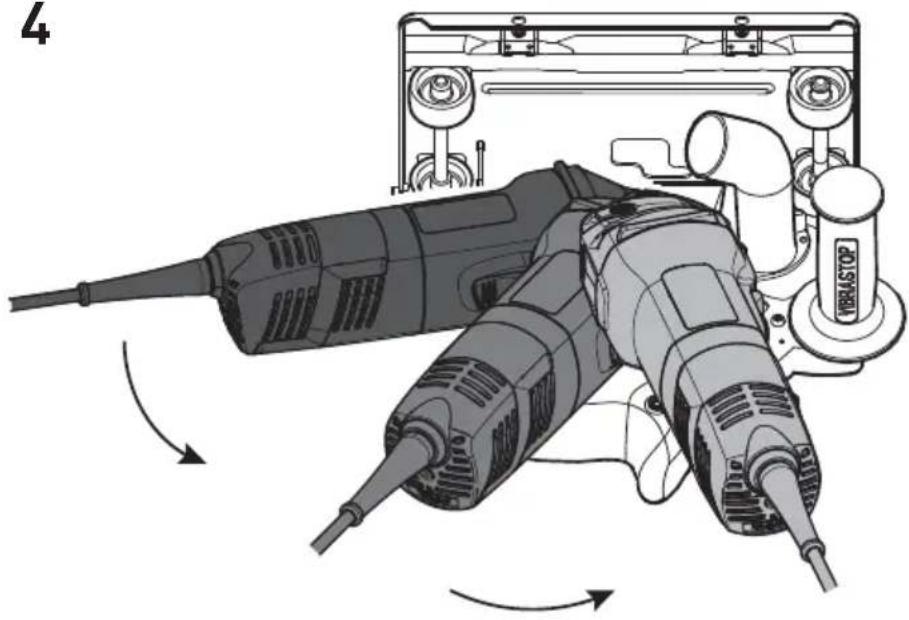
Before inserting the machine into the cover we recommend you to turn the machine case by 180° with respect to the gearbox so that the switch is on the right hand side.
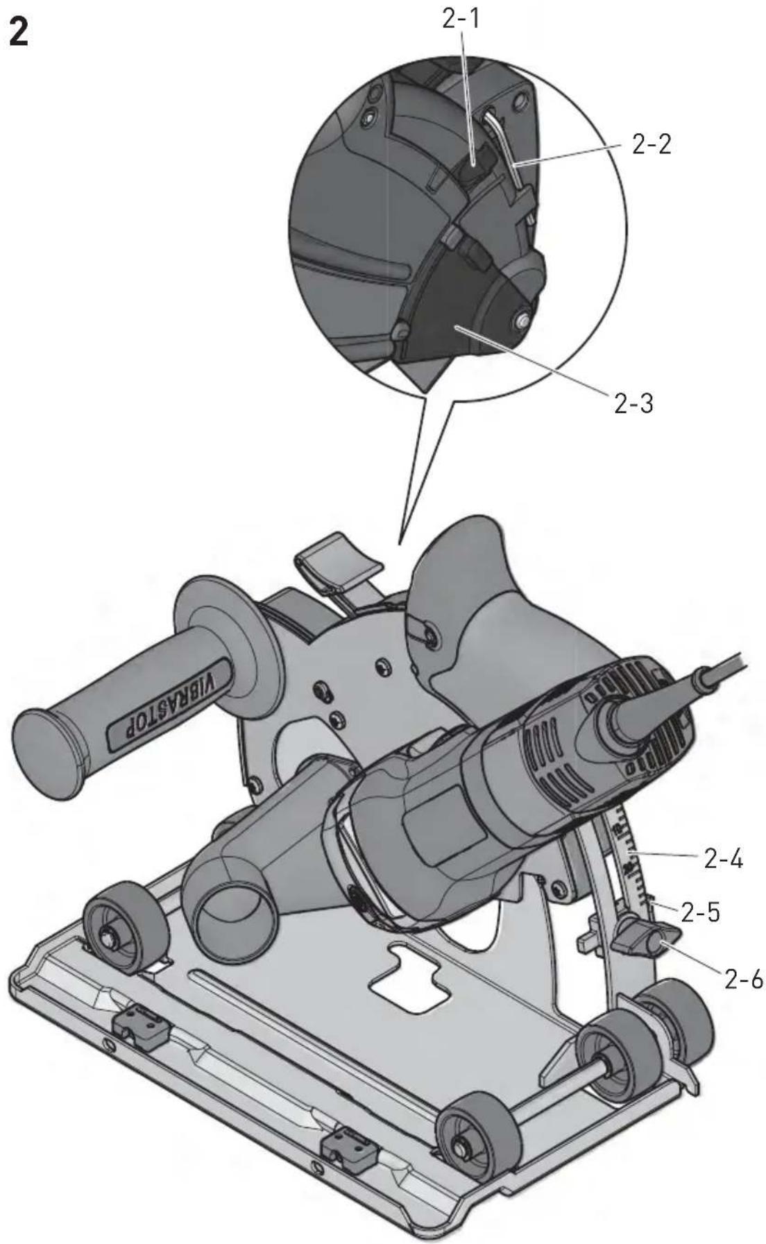
- Arrest the exhaust cover in the top position and put in on the side, with the clamping sleeve up. Then put the clamping neck [3-1] of the grinder into the sleeve. Put the guiding tabs [3-2] into the grooves on the clamping neck of the grinder – detail [3].
▶ Turn the grinder counter-clockwise to the suitable working position – cf. Fig. [4], set the cover to the maximum cut-through and arrest in this position.
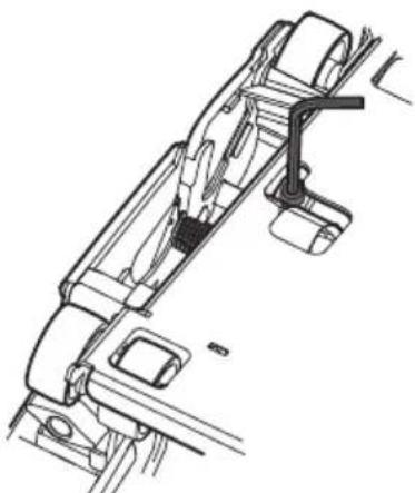
▶ Tighten sleeve with screw – Fig. [4 a]. When tightening, be careful about the correct right-angle setting of the grinder's bearing cover in the exhaust cover's sleeve.
Removal
▶ The cutting disc must be dismounted before the disassembly of the exhaust cover.
▶ Set the cover to a cut depth of 10 mm and put it down with the grinder at the bottom.
▶ Loosen screw of sleeve.
▶ Set the cover to the top position.
▶ Turn the guiding tab [5-1] into the groove on the grinder's clamping neck. The turning can be checked – the corresponding mark is on the side of the disc – Fig. [5].
Remove the cover from the grinder's clamping neck.
7.3 Dust extraction

WARNING
Dust hazard
▶ Always work with a dust extractor.
To ensure suction, put the hose of a Festool vacuum cleaner class L, M or H into the suction adapter [1-12].
Warning: Always work with the suction connected. Use exclusively antistatic vacuum cleaners to prevent discharges of static electricity in dusty environments.
8 Diamond cutting disc
8.1 Clamping

WARNING
Do not use quick-change nuts for clamping the disc!

WARNING
Only use diamond cutting discs recommended by the manufacturer and the prescribed fl angles included with the cover and the grinder.
-For reasons of safety, always use original Festool grinding discs!
-Sintered cutting discs must not be used!
-If the permissible revolution speed is given on the disc, it must not be lower than the highest no-load speed of the grinder.
-Discs with a permissible peripheral speed of 80 m/s and higher may be used.
-Test new cutting discs by letting them run for about one minute with no load.
-Unbalanced or vibrating discs should not be used and should be discarded.
-Protect grinding discs from shock, impact and lubricants.
-If the grinding and cutting wheels are worn down to the mark on the wheel guard (see the arrow sign), they should be replaced with new ones. This maintains the optimum grinding and
cutting performance of the machine (peripheral speed of the grinding and cutting wheels).
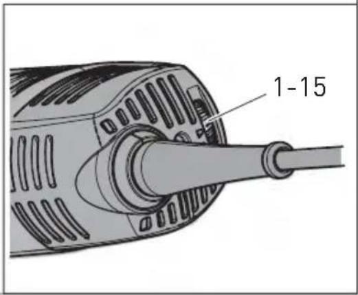
▶ Set the sliding stop for cut depth [2-5] on scale [2-4] to a depth value of 10 mm.
▶ Push the arresting button [1-1] and push the cover in.
▶ Release the arresting button [1-1] and let the cover be arrested when it gets to the set depth.
▶ Unlock with button [2-1] and fully open the disc cover.
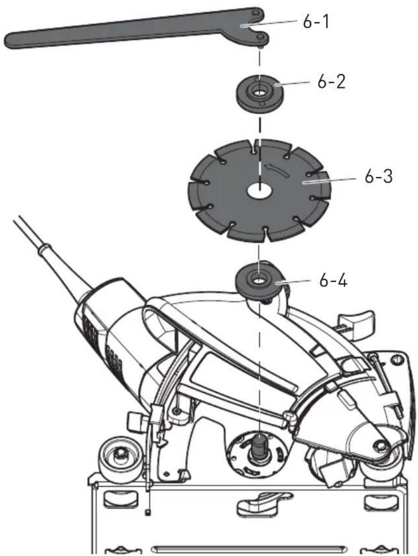
▶ Clean the flange [6-4] and clamping nut [6-2], as well as the clamping faces of the cutting disc [6-3].
- Put the flange [6-4] on the grinder's spindle with the shoulder facing outward.
Put on the disc [6-3]; take care to comply with the prescribed direction of rotation (arrow on the disc vs. arrow on the machine). The fl ange shoulder must exactly fit in the disc's opening.
▶ Screw on the clamping nut [6-2] with the shoulder facing outward (from the disc), press on the spindle arrest and tighten with wrench [6-1].
▶ Close the disc cover.
▶ Before switching on, check free rotational movement of the disc.
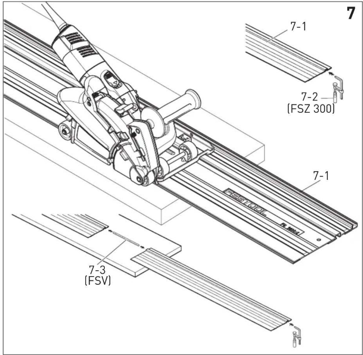
8.2 Guide system [fi gure 7]
![FESTOOL DSCAG 125 PlusFS - Guide system [fi gure 7] - 1](/content/2026/03/520113/images/ec9fd9d0e3632fb32983255828aba9de0dd33b6b3a1ef0bfe51b059a0a28b71a.jpg)
WARNING
Only use discs of thickness up to 3 mm!
Use the guide bar [7-1] for accurate cuts.
The side clearance of the disc guiding can be set with the aid of the adjusting screws [1-9] .
Guide bars
On the bottom face of the guide bar there are anti-skid strips, which ensure safe contact and prevent the workpiece from scratching.
The bar can also be secured with the aid of special clamps FSZ 300 [7-2], pushed into the special guide grooves. Safe guiding on uneven surfaces is thus enabled.

WARNING
The guide bars are equipped with burr protector, which must be cut off before the first use.
Connector
Depending on the particular application and the workpiece size, several guide bars can be connected with the aid of a connector spring [7-3]. Fast connection of guide bars can be secured by screws in the threaded openings.
9 Activation

WARNING
Risk of accident if the machine is operated using unauthorised voltages or frequencies.
The mains voltage and the frequency of the power source must correspond with the specifications on the machine's name plate.
In North America, only Festool machines with the voltage specifications 120 V/60 Hz may be used.
Set the sliding stop for cut depth [2-5] on scale [2-4] (top edge of the stop) to the requested depth of the cut – loosen and tighten the stop screw [2-6] as necessary.
The cut depth scale is valid for cutting without a bar.
The scale is for orientation only. The actual depth of the cut may be affected by, for example, manufacturing tolerances or the wear of the diamond disc's segment. If en exact depth is required, it is necessary to measure the actual depth on a test cut.
9.1 Switching on - off
Switching on
▶ Slide the on/off switch [1-5] forwards.
▶ Continuous operation: pressing the front part of the switch at the same time locks the on/off switch.
The electric power tool starts.
Only make contact with the material once the machine has reached operating speed.
Switching off
▶ Lift the electric power tool from the processed material.
▶ Release the on/off switch [1-5].
▶ During continuous operation: press on the rear part of the on/off switch [1-5].

WARNING
Risk of injury
Rebound, ejected parts
▶ Before setting down the machine, wait until the rotating tool has come to a complete stop.
9.2 Motor electronics
Starting current limitation
Electronically controlled continual running secures device acceleration without back thrust. Due to starting current limitation in the device, 16A protection is sufficient.

WARNING
Devices without starting current limitation need higher protection – at least 16A circuit breaker.
Speed control
You can regulate the speed steplessly within the speed range using the adjusting wheel [1-15] (see Technical data). This enables you to optimise the speed to suit the respective material. Please also note the specifications on the tools.
Switching off during back thrust
During sudden drop of revolutions, for example blocking in dividing cut, the current input in motor stops. For re-starting, the device must be first switched off and again switched on.
Protection against re-starting
Prevent uncontrolled starting of the device after current supply cut off. For re-starting, the device must be first switched off and again switched on.
Constant speed
The preselected motor speed remains constant through electronic control to ensure a uniform cutting speed even when under load.
Protection from overloading dependant on temperature
The safety electronics switches to cooling regime when the critical temperature is reached. Motor continues running at approximately 50 % revolutions, constant electronics is deactivated.
After cooling to approximately 10 - 20 s, the device is fully operational.
Heat protection for devices heated during operation, reacts adequately sooner.
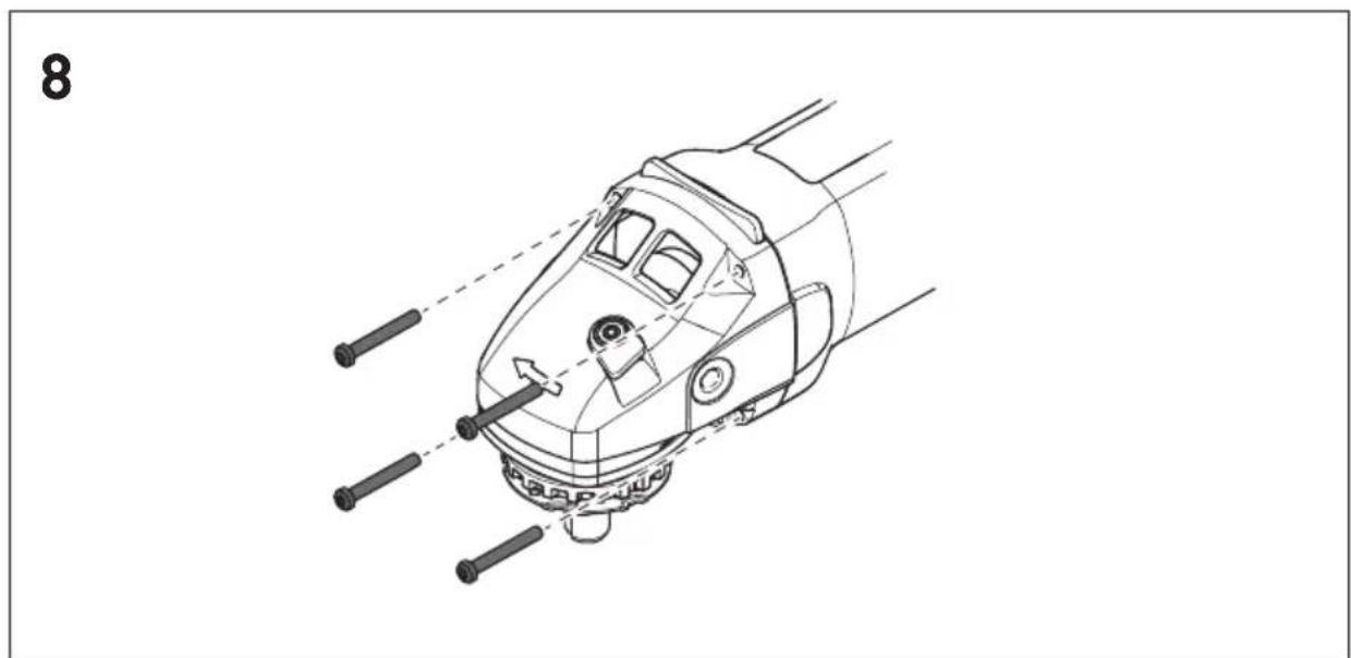
9.3 Turning the gear box
For special cases, the gearbox can be turned in steps of 90^ . This achieves a better handling position of the switch.
For such work, we recommend to use the Festool service.
▶ Remove four screws.
▶ Carefully, turn the gearbox into required position. Make sure the gearbox does not separate
from motor box by more than approximately 1 mm.
▶ Insert and fasten the four screws -figure [8].
9.4 Aperture cover
If you wish to see the cutting area, take off the aperture cover [2-3]. Only handle this cover when the disc is not running.
Be careful about spattering dust particles.
10 Service and maintenance

WARNING
Risk of accident, electric shock
▶ Always pull the plug out of the socket before performing any type of work on the machine.
▶ All maintenance and repair work which requires the motor housing to be opened, must only be carried out by an authorised service workshop.
- Wrapped electric tools can be stored in a dry place without heating, with temperatures not lower than -5^ . Unwrapped electric tools can only be stored in dry places with temperatures not lower than +5^ , without sudden changes in the temperature.
- To ensure the airflow is sufficient, cooling openings of the motor must be always clean and free.
-The machine is equipped with special self-disconnecting brushes. When the brushes are worn, the power supply is automatically disconnected, and the machine is stopped.
-If the suction fl ange height adjustment system does not operate smoothly, the fl ange must be removed and cleaned.

Customer service and repair. Only through manufacturer or service workshops: Please find the nearest address at: www.festool.com/service

Use only original Festool spare parts! Order No. at:
www.festool.com/service
11 Environment
Do not throw the power tool in your household
waste! Dispose of the machine, accessories and packaging at an environmentally-responsible recycling centre! Observe the valid national regulations.
EU only: In accordance with European Directive on waste electrical and electronic equipment and implementation in national law, used electric power tools must be collected separately and handed in for environmentally friendly recycling.
Information on REACH:
www.festool.com/reach

Vibrationsemission a_h=4,0 m/s^2
Målingens usikkerhed K = 1,5 m/s^2
Declaration of Conformity
We as the manufacturer Festool GmbH, Wertstraße 20, 73240 Wendlingen, Germany declare under our sole responsibility that the product(s):
Designation:
Designation of Type(s):
Serial number(s) 1):
Angle grinder
DSC-AG 125, DSC-AG 125 FH
201807
fulfills all the relevant provisions of the following UK Regulations:
S.I. 2008/1597
S.I. 2016/1091
S.I. 2012/3032
Supply of Machinery (Safety) Regulations 2008
Electromagnetic Compatibility Regulations 2016
Restriction of the Use of Certain Hazardous Substances in Electrical and Electronic Equipment Regulations 2012
and are manufactured in accordance with the following designated standards:
• BS EN 60745-1:2009 + A11:2010
• BS EN 60745-2-3:2011+A13:2015
• BS EN 55014-1:2017
• BS EN 55014-2:2015
• BS EN IEC 61000-3-2:2019
• BS EN 61000-3-3:2013
• BS EN IEC 63000:2018
1) in the specified serial number range (S-Nr.) from 400000000 - 499999999

Place and date of declaration: Wendlingen, 15.04.2021
Signed on behalf of and in name of Festool GmbH

Markus Stark
Head of Productdevelopment
i.v. Q Brandt
Ralf Brandt
Head of Productconformity