
AWTC Fp - Compressor Kärcher - Free user manual and instructions
Find the device manual for free AWTC Fp Kärcher in PDF.
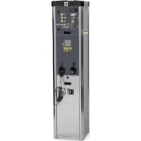


| Brand | Kärcher |
| Model | AWTC Fp |
| Product type | Compressor with tire inflation system and water distribution |
| Use | Professional |
| Dimensions (L x W x H) | 423 x 423 x 1760 mm |
| Weight | 71 kg |
| Electrical supply | 230 V / 50 Hz / 450 W |
| Protection rating | IP44 |
| Compressed air pressure | 0.1 to 0.8 MPa |
| Air flow rate | 100 l/min |
| Water supply pressure | 0.1 to 0.5 MPa |
| Temperature range with frost protection | -10 °C to +40 °C |
| Temperature range without frost protection | +5 °C to +40 °C |
| Sound power level (LWA) | 76.8 dB(A) |
| Sound pressure level (LpA) | < 70 dB(A) |
| Main functions | Tire inflation and deflation, non-potable water distribution |
| Calibration | Every 2 years (AWT-C and AWT-C Fp versions) |
| Daily maintenance | Empty coin cassette, check general condition |
| Weekly maintenance | Clean exterior, drain condensate |
| Frost protection | Manually activated frost protection heater (switch) |
| Safety | Emergency stop (STOP button), detailed safety instructions |
| Spare parts and accessories | Use only original Kärcher parts |
| Warranty | According to country conditions, material or manufacturing defects |
Frequently Asked Questions - AWTC Fp Kärcher
User questions about AWTC Fp Kärcher
0 question about this device. Answer the ones you know or ask your own.
Ask a new question about this device
Download the instructions for your Compressor in PDF format for free! Find your manual AWTC Fp - Kärcher and take your electronic device back in hand. On this page are published all the documents necessary for the use of your device. AWTC Fp by Kärcher.
USER MANUAL AWTC Fp Kärcher
12062 Cherasco (Cn) - Italy
Tel. +39 0172 427311
Fax +39 0172 495437
C.F./R.I./P.IVA/V.A.T.: IT 02469390047
Cap. Soc. € 255.000 - REA CN-178422
CCIAA
info@mtmhydro.it
PEC: mtmhydro@multipec.it
www.mtmhydro.it
Cherasco, 2018/09/01
Contents
General notes 5
Environmental protection 5
Accessories and spare parts.. 6
Safety instructions 6
Initial startup.. 6
Operation 6
Settings 7
Frost protection. 7
Shutting down 7
Care and service 8
Transport 8
Storage 8
Troubleshooting guide 8
Warranty 9
Technical data 9
EU Declaration of Conformity 9
General notes
Read these original instructions and the safety instructions chapter before using the
device.
device for the first time. Act in accordance with them.
Keep them safe for future reference or for future owners.
Environmental protection
The packing materials can be recycled. Please dispose of packaging in accordance with the environmental regulations.
Electrical and electronic appliances contain valuable, recyclable materials and often components such as batteries, rechargeable batteries or oil, which - if handled or disposed of incorrectly - can pose a potential threat to human health and the environment. However, these components are required for the correct operation of the appliance. Appliances marked by this symbol are not allowed to be disposed of together with the household rubbish.
Notes on the content materials (REACH)
Current information on content materials can be found at: www.kaercher.com/ REACH
Accessories and spare parts
Only use original accessories and original spare parts. They ensure that the appliance will run fault-free and safely. Information on accessories and spare parts can be found at www.kaercher.com.
Safety instructions
Hazard levels
DANGER
- Indication of an imminent threat of danger that will lead to severe injuries or even death.
WARNING
- Indication of a potentially dangerous situation that may lead to severe injuries or even death.
CAUTION
- Indication of a potentially dangerous situation that may lead to minor injuries.
ATTENTION
- Indication of a potentially dangerous situation that may lead to damage to property.
General
To avoid danger to persons, animals and property, it is imperative to read and observe the following documents before operating the device:
- Operating instructions
- All safety instructions. The respectively applicable national regulations.
In self-service operation, the operator must ensure that the users are informed by means of clearly visible information notices:
- Potential dangers
- Safety devices
- Operating the device.
Operation
WARNING
Children over the age of 8 and persons with reduced physical, sensory or mental capabilities, or those with a lack of experience and knowledge, are only allowed to use the appliance if they are properly supervised, have been instructed with respect to using the appliance safely by a person responsible for their safety, and understand the resultant dangers involved. Children must not play with the appliance. Cleaning and user maintenance may not be carried out by unsupervised children. Always keep the area around the device clean and free of oil and grease.
Behaviour in the event of an emergency
- In the event of an emergency, press the STOP button.
① "STOP" button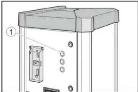
Symbols on the device

△ DANGER
Danger of injury from electrical voltage.
Do not open any covers marked with this symbol.
Do not open any covers that are marked in this way.

Risk of burns from hot surfaces.
Do not touch components marked with this symbol.
Intended use
This device has two functions.
Regulating vehicle tyre pressures by increasing or decreasing pressure. Dispensing water that is not suitable for drinking.
Regulating vehicle tyre pressures by increasing or decreasing pressure. Dispensing water that is not suitable as drinking water.
During operation, the door must be closed and the cover must be attached.
This device is suitable for commercial use.
Calibration requirement
The tyre inflation system of the AWT-C and AWT-C Fp device versions is calibrated and must be checked by the responsible gauging office after installation and then every 2 years.
Initial startup
- Open the on-board water inlet.
- Switch on the on-board power supply.
- Open locks.
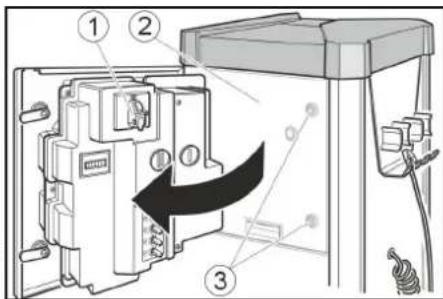
①Main switch ②Door ③Lock
- Set the main switch to "ON" position. The "STOP" button flashes when the device is in operation.
- Close the door.
Operation
AWT, AWT Fp operation
Control elements
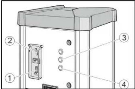
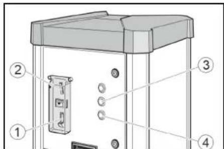
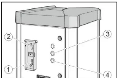
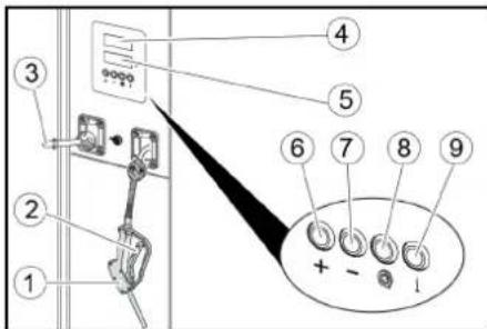
Coin return Coin slot ③ Tyre pressure button ④ Water dispenser button
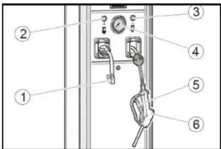
(1) Valve connector (2) Button + (3) Button - (4) Pressure gauge (5) Lever (6) Fuel pump nozzle
Drawing water


- Insert a coin in the coin slot.
- Press the water dispenser button.
- Hold the fuel pump nozzle in the container opening.
Pull the fuel pump nozzle lever until the desired filling level has been reached.
- Hang the fuel pump nozzle back on the device.
Checking tyre pressure


- Insert a coin in the coin slot.
- Press the tyre pressure button.
- Secure the valve connector on the tyre valve.
- Read the tyre pressure at the pressure gauge.
- Increase the tyre pressure by pressing the + button or reduce it by pressing the - button.

- Remove the valve connector.
- Pull on the hose briefly and feed the hose in via the automatic hose reel.
AWT-C, AWT-C Fp operation Control elements
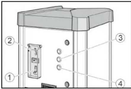
Coin return
(2) Coin slot ③ Tyre pressure button ④ Water dispenser button
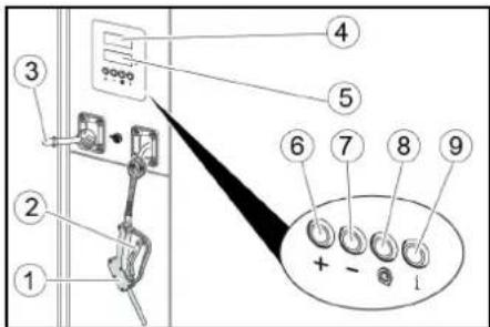
Fuel pump nozzle (2) Lever (3) Valve connector 4 Target pressure display (5) Tire pressure display @ Button + 7 Button - Flat tyre button No function
Drawing water

- Insert a coin in the coin slot.

- Press the water dispenser button.

- Hold the fuel pump nozzle in the container opening. Pull the fuel pump nozzle lever until the desired filling level has been reached.

- Hang the fuel pump nozzle back on the device.

Checking tyre pressure

- Insert a coin in the coin slot.

- Press the tyre pressure button.

- Set the target tyre pressure with the + and - buttons in the target pressure display (upper display).

- Secure the valve connector on the tyre valve. The tyre pressure display (lower display) shows the tyre pressure.

- Wait until an acoustic signal indicates that the tyre target pressure has been reached.

- Remove the valve connector.
7. Pull on the hose briefly and feed the hose via the automatic hose reel.
Filling flat tyres
If the tyre has no pressure, the device cannot detect that the valve connector has been connected to the valve.

- Insert a coin in the coin slot.

- Press the tyre pressure button.

- Set the target tyre pressure with the + and - buttons in the target pressure display (upper display).

- Secure the valve connector on the tyre valve. The tyre pressure display (lower display) shows the tyre pressure.

- Press the "Flat tyre" button.

- Wait until an acoustic signal indicates that the tyre target pressure has been reached.

- Remove the valve connector.
- Pull on the hose briefly and feed the hose via the automatic hose reel.
Settings
Setting the run time
Note
The adjustable run time applies to the insertion of one of the following coins:
50 Eurocents, 50 British pence, 1 Swiss franc, 1 Polish zloty, 5 Norwegian Kroner. Customer Service can set up different types of coins.
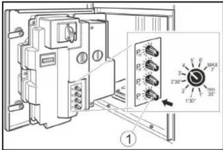
- Set the run time with the P I rotary knob. Possible setting range of 30 seconds to 7 minutes.
Rotary knob P1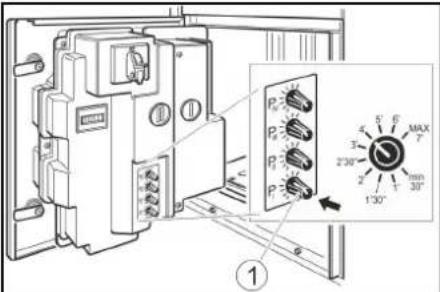
Note
Rotary knobs P II, P III and P IV have no function.
Frost protection
Device with frost protection
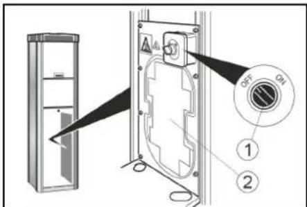
- Turn the frost protection switch "ON" at temperatures below +5°C.
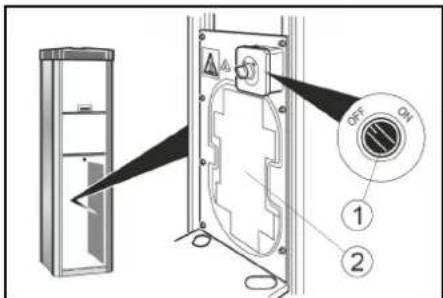
Frost protection switch ② Frost protection heater
ATTENTION
Risk of damage
The frost protection is active only when the main switch is "ON".
When activating the frost protection, check whether the main switch is in the "ON" position.
Note
The frost protection heater is not thermostat-controlled. When switched on, the heater is continuously in use.
Device without frost protection
In a device without frost protection, a shutdown must be carried out if there is risk of frost.
Shutting down
- Close the water inlet
- Drain the condensate in the compressed air tank (see "Maintenance tasks").
- Set the main switch to the "OFF" position.
Shutdown in the case of potential frost
- Close the water inlet.
- Remove water from the device and supply line.
- Drain the condensate from the compressed air tank (see "Maintenance work").
- Set the main switch in "OFF" position.
Care and service
Daily
- Empty the coin cassette (see "Maintenance tasks").
- Check the general condition of the device.
- Check the condition of the valve connector.
- Check the condition of the hose lines.
- Open the lower cover and check the condition of the compressor.
- Have damaged parts replaced.
Weekly
- Clean the outside of the device.
- Drain the condensate in the compressed air tank (see "Maintenance tasks").
ATTENTION
Risk of damage
The water in the compressed air line can damage the tyre pressure sensor.
Drain the condensate in the compressed air tank regularly.
Service every 2 years
Only with AWT-C, AWT-C Fp
- Have the pressure measuring device of the tyre inflator calibrated by the gauging office.
Maintenance work
Emptying the coin cassette
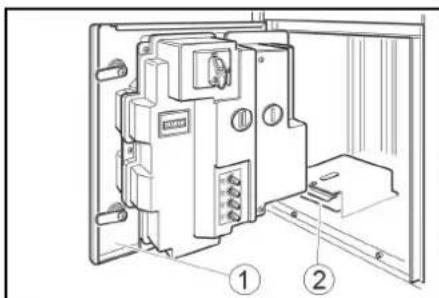
- Open the door.
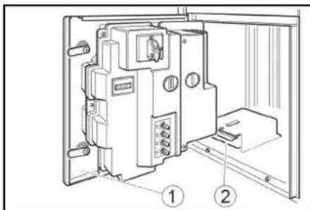
① Door ② Coin cassette
- Remove and empty the coin cassette.
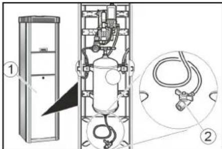
Drain the condensate
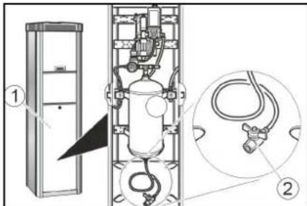
- Remove the cover.
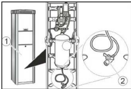
① Cover
② Condensate drain valve. Hold the condensate drain valve over a shaft or collecting container.
△ WARNING
Risk of injury, risk of damage
The water stream escaping from the condensate drain valve can cause injury or damage.
Never point the condensate drain valve at people, animals, the device or electrical components.
- Slowly open the condensate drain valve and drain the condensate.
- Close the condensate drain valve.
- Attach the cover.
Transport
CAUTION
Risk of injury, risk of damage
Be aware of the weight of the device during transportation.
- When transporting in vehicles, secure the device against slipping and tipping over according to the applicable guidelines.
Storage
CAUTION
Risk of injury and damage
Be aware of the weight of the device during storage.
Troubleshooting guide
△DANGER
Danger from electric shock.
Before working on the device, set the main switch to "OFF" and disconnect the onboard power supply.
The device does not work
- Check the on-site voltage supply.
- Set the main switch to "ON" position.
- Contact customer service.
The device does not start after the valve connector has been connected to the tyre.
- Check that the valve connector is seated correctly.
- Check the condition of the hose and of the valve connector. Press the "tyre flat" button.
There is no compressed air
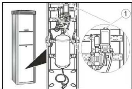
Pull the compressor on-button upward.
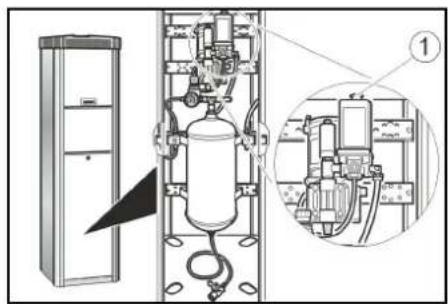
① Compressor on-button The compressor is overheated: Wait until the compressor has cooled off.
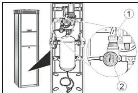
The tyre pressure is too low
- Check the pressure on the pressure gauge. Readjust the pressure reducer if necessary.
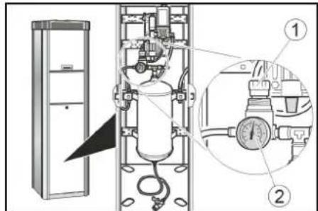
① Pressure reducer ② Pressure gauge
Malfunctions with information shown on the display
| Fault Cause Rectification | ||
| ER1 Unstable pressure measurement due to defective valve connector or hose | Replace the valve connector. Replace the hose. | |
| ER2, ER7 The tyre pressure is too low. Unstable pressure measurement due to defective valve connector or hose. | Check the tyre pressure on the pressure gauge and readjust the pressure reducer if necessary. Replace the valve connector. Replace the hose. | |
| ER3 | The tyre pressure is too low. | Check the pressure on the pressure gauge and read-just the pressure reducer if necessary. |
| ER4 | The tyre pressure is too high. | Check the pressure on the pressure gauge and read-just the pressure reducer if necessary. |
| ER5 | The voltage supply is disturbed. | Contact customer service. |
| ER6, ER8, ER9, ERU, ERB | Malfunction in the electronics. | Contact customer service. |
| ERP | The valve connector came loose during inflation. The tyre pressure is not stable. | Check that the valve connector is seated correctly. Check the pressure on the pressure gauge and read-just the pressure reducer if necessary. |
Warranty
The warranty conditions issued by our relevant sales company apply in all countries. We shall remedy possible malfunctions on your appliance within the warranty period free of cost, provided that a material or manufacturing defect is the cause. In a warranty case, please contact your dealer (with the purchase receipt) or the next authorised customer service site. (See overleaf for the address)
Technical data
Electrical connection
| Mains voltage V 230 | ||
| Phase ~ 1 | ||
| Frequency Hz 50 | ||
| Power rating W 450 | ||
| Degree of protection IP44 | ||
| Compressed air | ||
| Flow rate | l/min | 100 |
| Pressure | MPa | 0,1...0,8 |
| Water connection | ||
| Feed pressure | MPa | 0,1...0,5 |
| Ambient conditions | ||
| Temperature with frost protection | °C | -10...+40 |
| Temperature without frost protection | °C | +5...+40 |
| Humidity | % | 10...80 |
| Noise emission | ||
| Sound pressure level LpA | dB(A) | <70 |
| Sound power level LWA + K uncertaintyWA | dB(A) | 76,8 |
| Sound power level LWA + uncertainty KWA | dB(A) | 4 |
| Dimensions and weights | ||
| Weight | kg | 71 |
| Length | mm | 423 |
| Width | mm | 423 |
| Height AWT | mm | 1550 |
| Height AWT-C | mm | 1760 |
Subject to technical modifications.
EU Declaration of Conformity
We hereby declare that the machine described below complies with the relevant basic safety and health requirements in the EU Directives, both in its basic design and construction as well as in the version placed in circulation by us. This declaration is invalidated by any changes made to the machine that are not approved by us. Product: Tyre inflator Type: AWT, AWT Fp, AWT-C, AWT-C Fp
Currently applicable EU Directives 2006/42/EC 2014/35/EU 2014/30/EU

Documentation supervisor: Gianmarco Stra
MTM Hydro Srl
Via Moglia, 33
12062 Cherasco (Cn) - Italy
Tel. +39 0172 427311
Fax +39 0172 495437
CF / RI / P.IVA / VAT: IT 02469390047
Share capital €255,000 - REA CN-178422
Chamber of Commerce
info@mtmhydro.it
Certified email: mtmhydro@multipec.it
www.mtmhydro.it
Cherasco, 2018/09/01
Contents
General remarks 9
Order AWT-C, AWT-C Fp
12062 Cherasco (Cn) - Italy
Tel. +39 0172 427311
Fax +39 0172 495437
Tax code/Company register/VAT number: IT 02469390047
Share capital €255,000 - REA CN-178422
Chamber of Commerce
info@mtmhydro.it
PEC: mtmhydro@multipec.it
www.mtmhydro.it
Cherasco, 2018/09/01
Indices
Wait until the compressor cools down.
Type: AWT, AWT Fp, AWT-C, AWT-C Fp
12062 Cherasco (Cn) - Italy
Tel. +39 0172 427311
Fax +39 0172 495437
C.F./R.I./P.IVA/V.A.T.: IT 02469390047
Cap. Soc. 255 000 € - REA CN-178422
CCIAA
info@mtmhydro.it
PEC: mtmhydro@multipec.it
www.mtmhydro.it
Cherasco, 01/09/2018
Contents
Type: AWT, AWT Fp, AWT-C, AWT-C Fp
Applicable EU Directives
2006/42/EC
2014/35/EU
2014/30/EU
- Note on the use of elastomeric parts.

- Check the head on the elastomer base.

Operation of AWT-C, AWT-C Fp
Control handles
Turn the knob
12062 Cherasco (Cn) - Italy
Tel. +39 0172 427311
Fax +39 0172 495437
C.F./R.I./P.IVA/V.A.T.: IT 02469390047
Cap. Soc. € 255.000 - REA CN-178422
CCIAA
info@mtmhydro.it
PEC: mtmhydro@multipec.it
www.mtmhydro.it
Cherasco, 2018/09/01
Table of contents
General warnings 48
Environmental protection 48
Accessories and spare parts 48
Type: AWT, AWT Fp, AWT -C, AWT -C Fp
Calibration necessity
The calibration device in the AWT-C and AWT-C Fp versions is calibrated and must be checked by the responsible standardization body after installation, and then every 2 years.
- Open the water supply valve at the installation site. 2. Turn on the power supply at the installation site. 3. Open the locks.
Main switch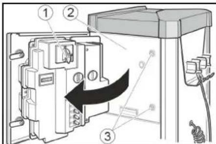
②Door (3) lock 4. Set the main switch to the "ON" ("I") position. The "STOP" button lights up when the device is operating. 5. Close the door.
Control
Control AWT, AWT F
Control elements
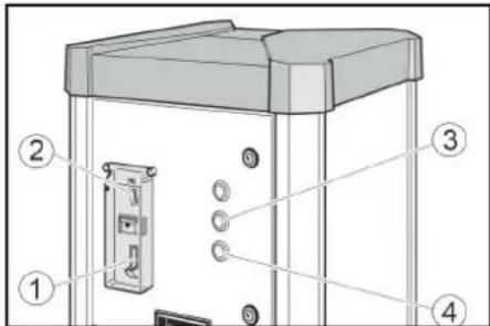
①Coin return ②Coin acceptor ③Pressure button (4) Water dispensing button
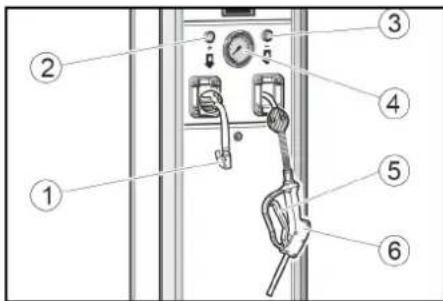
① Ventilation grille (2) "+" button 3"-" button 4Pressure gauge (5) Lever ⑥Filling hose
Filling

- Insert coin into coin acceptor.

- Press the water dispensing button.

3. Insert the filling hose into the reservoir opening. Press the filling hose lever until the required filling level is reached.

- Hang the filling hose back on the device.
Pressure check

- Insert the coin into the coin slot.

- Press the pressure button.

3. Secure the plug on the valve.

Anti-freeze protection
Anti-freeze protection device
1. At temperatures below +5°C, turn the anti-freeze protection switch to the «ON» position.
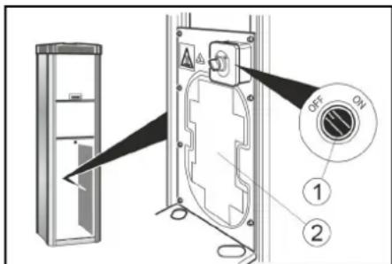
① Anti-freeze protection switch ② Heating element for anti-freeze protection
WARNING
Danger of damage
Anti-freeze protection is active only if the main switch is in the «ON» position.
When the anti-freeze protection is activated, check that the main switch is in the «ON» position.
Note
The heating element for anti-freeze protection does not have thermostatic regulation. In the switched-on state, the heating element operates continuously.
Device without anti-freeze protection
For devices without anti-freeze protection, if there is a risk of freezing, it is necessary to perform the drain procedure or if there is a risk of freezing.
1. Close the shut-off valves. 2. Drain the condensate from the compressed air reservoir (see "Maintenance"). 3. Set the main switch to the "OFF" position ("Off").
Remove from service if there is a risk of freezing.
- Close the water supply line.
- Remove the plug from the device's water supply pipe. 3. Drain the condensate from the compressed air reservoir (see "Maintenance"). 4. Set the main switch to the "OFF" position ("Off").
Care and Maintenance
Daily
- 1. Empty the coin cassette (see "Maintenance"). 2. Check the general condition of the device.
- 3. Check the condition of the ventilation grille. 4. Check the condition of the cables.
- 5. Open the lower housing and check the condition of the compressor. 6. Replace damaged parts.
Weekly
- 1. Clean the device externally. 2. Drain the condensate from the compressed air reservoir (see "Maintenance").
WARNING
Risk of damage
Water in the compressed air line can damage the pressure switch and other components. Regularly drain the condensate from the compressed air reservoir.
Maintenance every 2 years
Only AWT-C, AWT-CFp
- Calibrate the pressure measuring device of the pump in the standardization center.
Maintenance work
Emptying the coin cassette
- Open the door.
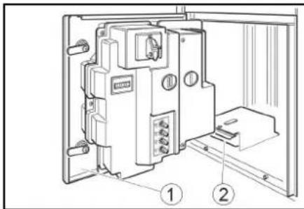
① Door ② Coin cassette
- Remove the coin cassette and empty it.
Condensate drain
- Remove the cover.
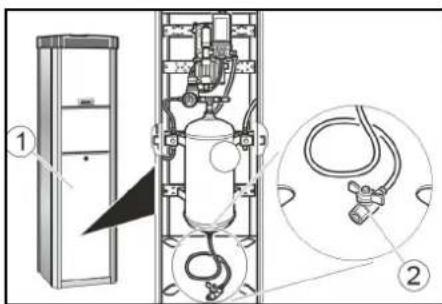
① Cover ② Condensate drain valve
- Hold the drain valve over a container.
WARNING
Risk of injury, risk of burns
The water jet coming out of the drain valve and condensate can cause injury or burns. Never point the drain valve and condensate at people, animals, devices, or electrical components.
- Open the condensate drain valve and drain the condensate. 4. Close the condensate drain valve. 5. Install the casing.
Transportation
CAUTION
Danger of injury, danger of damage
When transporting, take into account the weight of the device.
1. When transporting the device in vehicles, secure it against shifting and tipping in accordance with the applicable regulations.
Storage
CAUTION
Danger of injury and damage
During storage, take into account the weight of the device.
Repair and maintenance
DANGER
Danger of electric shock.
Before working on the device, set the main switch to the OFF position and disconnect the power supply.
The device does not work
Open the inspection cover.
- Set the main switch to the «ON» («I») position.
- Contact the service department.
The device does not start after connecting the power plug to the mains.
- Check the correct position of the plug. Check the condition of the plug cord. Press the trigger button.
No supply air.
- Press the compressor ON button.
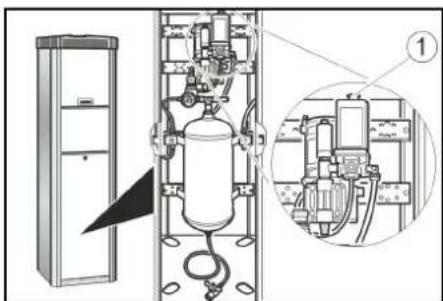
① Compressor ON button - the compressor will start; wait until the compressor stops.
Air pressure too low.
The pressure is set incorrectly.
We reserve the right to make technical changes.
EC Declaration of Conformity
We hereby declare that the construction and design of the machines listed below comply with the applicable essential requirements of the EC Directives on safety and health protection. Any modification of the machine not approved by our company will render this declaration invalid. Product: Compressor Type: AWT, AWT Fp, AWT-C, AWT-C Fp
Applicable EC Directives
2006/42/EC
2014/35/EC
2014/30/EC
Documentation: Gianmarco Stra
MTM Hydro Srl
Via Moglia, 33
12062 Cherasco (Cn) - Italy
Tel.: +39 0172 427311
Fax: +39 0172 495437
C.F./R.I./P.IVA/V.A.T.:IT 02469390047
Cap. Soc. € 255.000 - REA CN-178422
CCIAA
info@mtmhydro.it
PEC: mtmhydro@multipec.it
www.mtmhydro.it
Cherasco, 2018/09/01
Contents
Type: AWT, AWT Fp, AWT-C, AWT-C Fp
Relevant EU Directives
2006/42/EC
2014/35/EU
2014/30/EU
Authorized person for documentation: Gianmarco Stra
MTM Hydro Srl
Via Moglia, 33
12062 Cherasco (Cn) - Italy
Tel. +39 0172 427311
Operation of AWT-C, AWT-C Fp
Operating elements
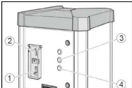
①Coin return
Relevant EU Directive
2006/42/EC
2014/35/EU
2014/30/EU
Person authorized to compile the technical documentation: Gianmarco Stra
MTM Hydro Srl
Via Moglia, 33
12062 Cherasco (Cn) - Italy
Tel. +39 0172 427311
Fax +39 0172 495437
Tax Code / Company Register / VAT: IT 02469390047
Share Capital €255,000 - REA CN-178422
Chamber of Commerce
info@mtmhydro.it
Certified Email: mtmhydro@multipec.it
Contents
Only for AWT-C, AWT-C Fp
- Have the pressure measuring device in the tire inflation device calibrated by a calibration authority.
Maintenance work
Emptying the coin cassette
- Open the door.
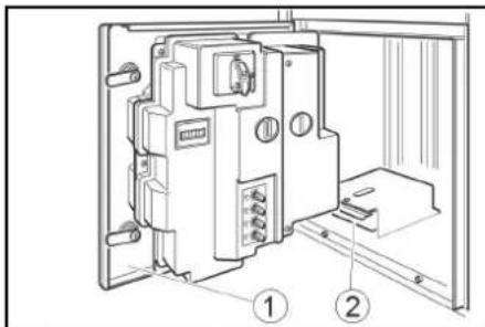
① Door ② Coin cassette 2. Pull out the coin cassette and empty it.
Draining condensate
- Remove the cover.
Share capital €255,000 - REA CN-178422
CCIAA
info@mtmhydro.it
PEC: mtmhydro@multipec.it
www.mtmhydro.it
Cherasco, 01.09.2018
Contents
Operating notes 79
Environmental protection 79
Safety instructions 87
Commissioning 87
Maintenance 87
Settings 88
Protection against freezing 89
Cleaning the windows 89
Page 89
Transport 89
Storage 89
Help in case of damage 89
Warranty 90
Technical data 90
EU Declaration of Conformity 91
General instructions

Before first use, read this original manual carefully
for operation and safety instructions. Follow them accordingly. Keep the operating manual for future reference or for the new owner.
Environmental protection

Packaging materials are recyclable. Please dispose of
packaging in an environmentally friendly manner.

Electrical and electronic devices contain materials,
recycling regulations, and sometimes
Components, batteries, and oil filters that are no longer properly disposed of can pose a potential hazard to human health and the environment. For the proper functioning of the device, all components must be present. Devices marked with this symbol must not be disposed of with household waste.
Information on ingredients (REACH)
Current information on ingredients can be found at: www.kaercher.com/REACH
Accessories and spare parts
Only use original accessories and original spare parts. They ensure the safe and trouble-free operation of the device. Information on accessories and spare parts can be found at: www.kaercher.com.
Safety instructions
Hazard levels
DANGER
- Indication of an imminent danger that can lead to serious injuries or even death.
WARNING
Indication of a potentially dangerous situation that can lead to serious injuries or even death.
CAUTION
- Indication of a potentially dangerous situation that can lead to minor injuries.
ATTENTION
- Indication of a potentially dangerous situation that can lead to property damage.
To avoid danger to people, animals and property, before operating the device, read and keep the attached documents.
The operating instructions must comply with the safety regulations of the relevant national legislation.
In service mode, the owner must provide the necessary information through the specified indicators regarding:
Possible dangers - intended use - servicing of the device.
Service
WARNING
- Children aged 8 and above, and persons with reduced physical, sensory or mental capabilities, or lacking experience and knowledge, may use the device only under proper supervision, after being instructed on safe use and understanding the hazards involved.
- Children must not play with the device.
- Cleaning and user maintenance must not be performed by children without supervision. Keep the area around the device clean and free of grease and dirt.
Behavior in case of emergency
Press the "STOP" button when the device is running.
- Close the doors.
Service
Service of the device, device group
(1) Coin slot ② Coin return button ③ Pump pressure button ④ Water supply button
(1) Valve lever ② Button + ③ Button - (4) Pressure gauge (5) Nozzle ⑥ Piston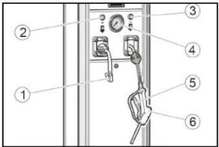
Water supply
1. Insert a coin into the coin slot.
2. Press the water supply button.
3. Keep the nozzle opening in the reservoir. Hold the nozzle until the desired amount of water is filled.
4. Close the nozzle and turn off the device.
Checking the pump pressure
1. Insert a coin into the coin slot.
2. Press the pump pressure button.
3. Close the valve lever and the valve.
4. Read the pump pressure on the pressure gauge. 5. Increase the pump pressure by pressing the button + or decrease it by pressing the button -
- Close the valve lever.
7. The marking device will automatically mark the item when you leave it to be marked.
Maintenance of AWT-C, AWT-C FP
Maintenance elements
① Coin insertion ② Coin start slot ③ Pump start button ④ Water filling button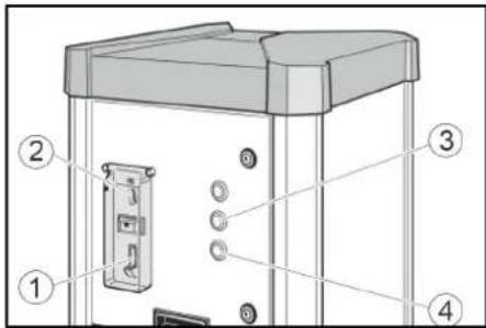
① Pistol ② Post ③ Lever for valve ④ Display for nominal pressure ⑤ Display for pump pressure ⑥ Button + ⑦ Button - ⑧ Button for stopping the pump if it does not work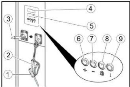
Water supply
1. Insert a coin into the coin start slot.
2. Press the water supply button.
3. Pull the pistol trigger from the reservoir. Keep the pistol pressed until the desired water pressure is reached. 4. Release the pistol trigger again.
Checking the pump pressure
1. Insert a coin into the coin start slot.
2. Press the pump start button.
3. Adjust the nominal pressure of the pump with the + and - buttons on the nominal pressure display (upper display).
4. Close the valve lever of the pump valve. The pressure display for the pump (lower display) shows the pump pressure.
5. Listen until the acoustic signal indicates that the nominal pressure of the pump has been reached.
6. Open the valve lever. 7. Pull the trigger briefly and leave it to be wound by the automatic winding drum.
Hanomnete cnaHannTe rymn
If the pressure cannot be adjusted, the valve cap may have been placed on the valve.
1. Insert a coin into the coin slot.
2. Press the inflation button.
3. Adjust the nominal pressure of the tire with the + and - buttons on the nominal pressure display (upper display).
4. Secure the valve cap on the valve of the tire. The display for tire pressure (lower display) shows the tire pressure.
5. Press the "Start" button.
6. Wait until the acoustic signal indicates that the nominal pressure of the tire has been reached.
7. Remove the valve cap. 8. Briefly press the start button and leave it to automatically adjust the pressure.
Adjustment
Adjusting the operating time
Note
It is possible to adjust the operating time when starting with one of the following coins:
50 euro cents - 1 British pound - 1 Swiss franc - 5 Norwegian kroner
The use of other coins can be adjusted by the service department.
1. The time relay operates with a delay. The adjustment range is from 30 seconds to 7 minutes.
①Turn on P1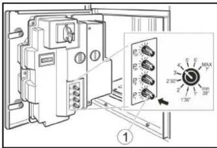
Note
Do not turn on P II, P III and P IV simultaneously.
Protection against freezing
Device for protection against freezing
1. At temperatures below +5°C, set the switch for protection against freezing to "ON".
Device for protection against freezing
The device for protection against freezing, in case of danger of freezing, must be drained during shutdown from operation in case of danger of freezing.
Shutdown from operation
- Close the water supply. 2. Drain the condensate from the reservoir for the air system (see "Operation for maintenance").
- Set the main switch to "OFF".
Shutdown from operation in case of danger of freezing
- Close the water supply.
- Drain the water from the device and close the shut-off valves.
3. Drain the condensate from the reserve tank for the air system (see "Maintenance"). 4. Set the main pressure switch to "OFF".
Maintenance
Daily
- Drain the condensate from the reserve tank (see "Maintenance").
- Check the condition of the air filter.
- Check the condition of the belt and pulley. 4. Check the condition of the main pipeline.
- Open the drain valve and check the condition of the compressor.
- Leave the repair of damaged parts to a specialist.
Weekly
1. Check the air filter. 2. Drain the condensate from the reserve tank for the air system (see "Maintenance").
WARNING
Risk of injury
The water in the air system can damage the sensors for the air pressure.
Always drain the condensate from the reserve tank for the air system.
Maintenance every 2 years
- The device is intended for measuring the voltage of the charging device for batteries, for calibration by the metrological service.
Maintenance
Replacing the coin battery
- Open the cover.
Cover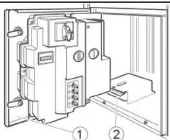
② Coin battery
- Remove and replace the coin battery.
Draining the condensate
- Remove the cap.
① Cap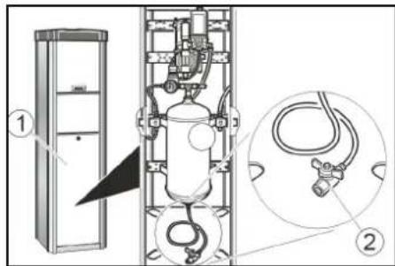
② Drain the condensate through the drain valve. The drain valve for condensate is located on the collection container.
WARNING
Danger of burns, danger of injury
It is possible that hot condensate may escape from the drain valve and cause burns or injury.
Open the condensate drain valve to remove condensate from the air.
Air, gas, or electrical components.
- Open the condensate drain valve and drain the condensate.
- Close the condensate drain valve.
- Replace the cap.
Transportation
Danger from heating, danger from injury. When transporting, follow the safety instructions.
1. When transporting, follow the safety instructions and use the protective equipment as specified in the manual.
Storage
DANGER
Danger from heating and injury
When storing, keep in mind the temperature of the device.
Help in case of damage
DANGER
Risk of electric shock. Before starting work on the device, set the main switch to "OFF" and disconnect it from the power supply.
The device does not work
- Check the connection to the mains supply.
- Set the main switch to the "ON" position.
- Information for the service technician.
The device does not start, possibly because the main fan is not connected to the power supply.
- Check the correct position of the main fan.
- Check the condition of the fuse and the main fan.
- Press the "Start" button and check that there is air flow.
- Remove the cover to turn on the compressor.
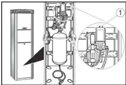
① Switch for turning on the compressor
- The compressor stops: wait until the compressor cools down. The air pressure is hard and low.
- Check the pressure on the manometer. If necessary, adjust the setting of the pressure reducer.
12062 Cherasco (Cn) - Italy
Tel. +39 0172 427311
Fax +39 0172 495437
C.F./R.I.PIVA/V.A.T.:IT 02469390047
Cap. Soc. € 255.000 - REA CN-178422
CCIAA
info@mtmhydro.it
PEC: mtmhydro@multiptec.it
www.mtmhydro.it
Cherasco, 2018/09/01
Table of Contents
General instructions 91
Environmental protection 91
Equipment and spare parts. 91
Safety instructions 91
Starting up 92
Handling. 92
Settings 93
Frost protection. 93
Shutting down. 93
Type: AWT, AWT Fp, AWT-C, AWT-C Fp
Relevant EU directives
2006/42/EU
2014/35/EU
2014/30/EU
Documentation officer: Gianmarco Stra
MTM Hydro Sr
Via Moglia, 33
12062 Cherasco (Cn) - Italia
Tel +39 0172 427311
Only with AWT-C, AWT-C Fp
- Have the calibration station calibrate the pressure measuring device of the tire inflation system.
Maintenance work
Technical characteristics 106
Declaration of Conformity with EU Standards 106
General instructions
Precautions
Before using the device, read the original operating instructions and the main safety instructions carefully. Follow them accordingly.
Keep the instructions for future use or for the next owner.
Environmental protection
Packaging materials are suitable for recycling. Dispose of packaging

without harm to the environment.

This device contains electrical and electronic components and therefore must be disposed of separately from household waste.
This device contains electrical and electronic components and therefore must be disposed of separately from household waste. At the end of its service life, the device must be returned to the appropriate collection point. The device is marked with the symbol shown below. Do not dispose of the device with household waste.
Information on components (REACH)
Current information on components is available at: www.kaercher.com/REACH
Accessories and spare parts
Only use original accessories and original spare parts. They ensure the safe and trouble-free operation of the device.
Information on accessories and spare parts is available at www.kaercher.com.
Safety instructions
Hazard levels
DANGER
Indicates an imminent danger that will lead to severe or even fatal injuries.
WARNING
Indicates a potentially dangerous situation that could lead to severe or even fatal injuries.
CAUTION
Indicates a potentially dangerous situation that could lead to minor injuries.
Read the manual before use! Remember safety, which can cause material damage.
General information
To avoid danger to people, animals, and property, before operating the device, you must familiarize yourself with the following documents and follow them:
Management of all safety instructions is carried out in accordance with legal norms;
In case of using the device, the operating person must be instructed on the use of the device by a responsible person to ensure safe operation:
danger; - device safety; device control.
Control
WARNINGS
Children over 8 years old and persons with reduced physical, sensory, or mental capabilities, as well as persons who do not have the necessary experience and knowledge, may use the device only if they are under proper supervision or have been instructed by a competent person on the safe use of the device and understand the possible risks. Do not allow children to play with the device. Cleaning and user maintenance must not be performed by children without supervision. After use, the device should be cleaned, wiped with a dry cloth, and stored.
In case of an emergency situation
- In case of an emergency situation, press the (STOP) button.
STOP button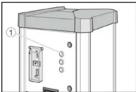
Symbols on the device

SAFETY
Danger through electric shock
Voltage.
Do not open the cover with a warning sign.

WARNING
Danger of injury from sharp surface.
Components with this symbol must not be.
Intended use
This device is functional.
Adjusting the pressure of car tires or scanning the pressure. Other use is not intended.
Operation in explosive environments is prohibited.
The pressure must be released before opening the housing.
This device is intended for professional use.
Calibration requirement
The devices of models AWT-C and AWT-C Fp are calibrated and must be immediately after installation, and then every 2 years be checked by a competent metrological service.
Commissioning
- Fill the water system with water. 2. Turn the taps on the water supply lines.
3. Open the locks.
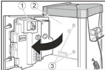
Turn the handle ② to the lock position. 4. Set the handle to the "ON" ("OPEN") position. When the device is ready, the "STOP" button will light up. 5. Close the handle.
Control
Control of devices AWT, AWT Fp
Control elements
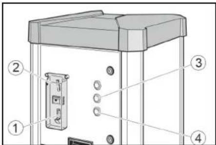
Coin return
① Coin slot ② Button for pressure in tires ③ Button for water
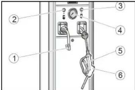
① Valve socket ② "+" button ③ "<-->" button ④ Pressure gauge ⑤ Lever ⑥ Spray gun
Filling

- Insert a coin into the coin slot.

2. Press the water button.

3. Insert the spray gun into the holder. Press the lever of the spray gun until the required filling level is reached.

4. Remove the spray gun from the holder.
Check the pressure in the tires

- Lower the coin into the coin receiver.

- Press the "Pressure in tires" button.

- Close the valve on the chamber inflation valve.

- Check the pressure in the tires using the pressure gauge. Increase the pressure in the tires by pressing the "+" button, or decrease it by pressing the "-" button.
- Close the valve.
- A little air will be supplied from the compressor for automatic inflation of the tire on the wheel rim.
CONTROL UNIT, CONTROL ELEMENTS
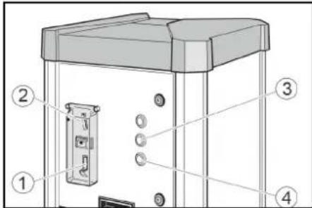
Check the coin ② Coin receiver ③ Pressure in tires button ④ Water drain button
① Air hose
② Valve (3) Valve opening ④ Pressure display ⑤ Pressure display in tires (6) "+" button ⑦ "-" button ⑧ "Pressure release" button ⑨ Function absent
INFLATION

- Insert the coin into the coin receiver.

- Press the water drain button.

3. Insert the inflation hose into the tire valve. Press the inflation hose valve until the required filling level is reached.

4. Then remove the inflation hose from the device.
Press the pressure button

- Release the pressure in the coin acceptor.

- Press the "Pressure in inches" button

3. Adjust the pressure setting in inches using the "+" and "-" buttons on the pressure setting display (upper display).

4. Close the valve opening on the ventilation chamber. The pressure display in inches (lower display) shows the pressure in inches.

5. Wait for the audible signal about reaching the set pressure in inches.

- Open the valve.
- Slightly press the lever for its further automatic winding on the drum of the planter.
Setting the pressure, if the pressure in inches is completely absent, the device cannot detect the presence of a pressure switch on the valve.

- Release the pressure in the coin acceptor.

- Press the "Pressure in inches" button

3. Adjust the pressure setting in inches using the "+" and "-" buttons on the pressure setting display (upper display).

4. Close the valve opening on the ventilation chamber. The pressure display in inches (lower display) shows the pressure in inches.

- Press the "Random number" button

6. Wait for the audible signal about reaching the set pressure in inches.

- 3HHTn po3'em KnaanaHa.

- Troxnotarynta wnaHr nnoI NOdaJIbwoRO abTOMaTHyHO HAMOTyBaHHHa 6apabahnlaNaHy.
HanaHTyBaHHa
HanaHTyBaHH TpNBanocTi po60n Bka3ieKa
Tpueanicmb po6omu moxha Hanaumoeyamu dny npuimae maux MOhem:
50 8poueHmis 50 6pumahcbkux neHHI 1wueuapcbkuiΦpaHK 1 nonbcku 3nou - 5 Hop8e3bKux KPOH
HwMoHemu Moxymb HanaumoeyeamucbccepeichoCnyk601.
- BidapeyIIOBAtn TpnbAicbpo60Tu 3a DOnOMOrOIO NOBOPOThoi pyuKn P I. MoKINBNI Diana3OH HanaWtYBaHH BId 30 cekyHd Do 7 XbnnH.
① NobopoTHa pyuKa P I
Bka3i8ka
Poeopomhi pyku P II, P III ma P IV HeakmuHi.
3axnct BiMOP03y
Pnucpii i3 3axnctOM BiD 3amep3aHH
- 3a TemnepaTpy HnKue +5°C NobepHyTu BmNKau 3axNCTu BiD 3aMep3aHnB B NIOJoxKeHHRA «ON» («YBMK.»).
(1) Bumkaay 3axncty BiD 3amep3aHHA ② HarpibaIbHn enEmeHT nIaXnCTy Bi3aMep3aHH
YB4A
He6e3neKa nowkoDxehH
Cucmema 3axumy eid 3amep3aHHa kmuHa nuue modi, konu zonoeHuBumukay 3haxodmbcra y nooKeHHI (YBIMK.)
Iid yac akmueaui cuumemu 3axucmy eio 3amep3aannepeepme, yu 3haxodumbcra 20o8hu bumukay y nooxkenni «ON».
Bka3ieKa
HaepaBnHn enemn dna 3axucmy bid 3amep3aHH He maecmpmamuunho2o peeynoaHH. B yimkhymomy cmani haepaBnHu enemn npauoc mpueanu yac.
Pnctpi633axncty Bi3aMep3aHH
Ypa3i He6e3neKn 3aMeP3aHHn npncTpoO 6e3 cncTeMn 3axNCTy BID 3aMeP3aHHn cnId BIKoHaTN pOeDpy NOro BvBeEHn 3 ekCnIyataui.
BvBeDeHn3ekcnJnyatau
- NpeekpnN lihi BOdoonocTaayHn
- 3nTn KOHcHcAT 3 pe3epByapa dna CTncHeHOro NOBITpRA (INB. «Po6OtN 3 TEXHIHOro OcbnyroByaHHA»). 3.YctaHOBNTIROJOBHIN BUMNKaY noIOXeHHRAFF((BBMK.)
BnBeHn3eknnyatau y pa3i He6e3neKn 3aMep3aHH
1.3akpnTNIHIO BOJOnocTaaHHA 2. BuaaHTN BOy 3 npCTPO TO TpybONPOBOY niBedeHn. 3. 3nTn KOHcHcAT 3peepByapa nTn CTncHeHOro NOBITp(INB.《Po6OtN 3TexHiHOrO oCnyroByBaHHA) 4.BcTaHOBtI rONOBHn BmNKa y noIOKeHHRAFF((BUMK.)
OornyTaTexHiue 06cnyroByBaHHa
UoDHeHNO
1. Replace the coin cassette (see "Maintenance"). 2. Check the general condition of the device. 3. Check the condition of the valve connector. 4. Check the condition of the hoses. 5. Open the housing and check the condition of the compressor. 6. Damage to the timer.
LOTnXH
- Check the external part of the device.
- Drain the condensate from the receiver of the compressed air (see "Maintenance").
WARNING
Danger of injury
Water in the compressed air system can damage the pressure switch and other components.
Drain the condensate from the compressed air receiver regularly.
Maintenance every 2 years
Only for AWT-C, AWT-C Fg
- Calibrate the pressure gauge or have it calibrated by the metrology service.
Maintenance
Replacing the coin cassette
- Check the door.
1. Cover ② Coin cassette 2. Pull out the coin cassette.
- 3HRTN KOKyX.
①Kpniuka ② Kπaπa n 3nBy KOHDeHcaTy
- YtpmByaTn Klaanah 3NBy KOHDeHCaty Na KaHJOM a6o EMHicTIO nra 36opy.
△NONEPEDXEHH
He6e3neKa mpa8myeaHnHa, He6e3neKa nowkodkeHH
Cmpymnb eodu, uo buxodumb i3 knanana h 3nuey KOdehcamy, moke cnpuuHumu mpaemu abo nowkdoxeHH.
Hikou He cnpmaoyamu klanan3nuy KOHehcamyHa mOe,meapun npucpi afo enkmpuhy KOMnohehmu
- NobinbHO BiKpTN Klanan 3nBy KOHdeHcATy i 3nTn KOHdeHcAT.
- 3aKpntn Knaanah 3JINBy KOHDeHcaTy.
- YctaHOBUtn KOxOyX.
TpaHcnpTyBaHHa
△OBEPEXHO
He6e3neKa mpa8myeaHn, He6e3neKa nowkodxehn
Iid yacmpaHcnpmyBaHHepaxoeyeamu Macy npucmpoio.
1. When transporting, secure the device properly with the fasteners in accordance with the norms to prevent its movement and tipping.
Storage
CAUTION
Safety precautions against damage
When storing, take into account the mass of the device.
Assistance in case of malfunctions
DANGER
Danger of electric shock.
Before working with the device, set the main switch to the «OFF» («OFF») position and disconnect the power supply.
Device operation
- Check local electrical connections.
- Set the main switch to the (ON) (ON) position. Contact the service department.
The device does not start after pressing the start button.
- Check the correct installation of the connector.
- Check the condition of the plug and connector.
__SUPPIMER__
① Compressor switch button
The compressor will start and run until the compressor cools down.
Low air pressure
- Check the pressure with a manometer. If necessary, adjust the pressure regulator.
① Pressure regulator ② Manometer
Incorrect indication on the display
| Поминka Причina Усунна | ||
| ER1 | Hectabільne вимірювань{TSCK chpe3 noшкоженna роз' emу клала на aboшланг. | 3aminii p03'em klnanana.3aminii shlaehr. |
| ER2, ER7 | Tnck nobітprя занадTo hizbki. Hectabільne вимірювань{TSCK chpe3 noшкоженna вechтільношт ekра aboшланг. | Ipebeipntu Tnck 3a MaHometpom, y pa3i notpe6bviDperyliobatn peDyktop.3aminii p03'em klnanana.3aminii shlaehr. |
| ER3 | Tnck nobітprя занадTo hizbki. | Ipebeipntu Tnck 3a MaHometpom, y pa3i notpe6bviDperyliobatn peDyktop. |
| ER4 | Tnck nobітprя занадTo bscokni. | Ipebeipntu Tnck 3a MaHometpom, y pa3i notpe6bviDperyliobatn peDyktop. |
| ER5 | 3bɪe eNeKTPOXINBLENHЯ. | 3BepHyTnCJdo cnUkBiPiTrIMKn. |
| ER6, ER8, ER9, ERU, ERB | HecnpabNICTb eNeKTPOHOro obnaДнання. | 3BepHyTncjdo cnUkBiPiTrIMKn. |
| ERP | Poz'em klnanana oclab pi d qac nakauchyBaHnY.Tnck nobітprя не сtabільни. | Ipebeipntu npabInbHic'tb BCTaHOBlennhy po3'emy klnanana.Ipebeipntu Tnck 3a MaHometpom, y pa3i notpe6bviDperyliobatn peDyktop. |
Warranty
The warranty conditions set by our authorized organization apply to all products from our country. If a malfunction occurs during the warranty period, we will repair it free of charge, provided that the malfunction is due to material defects or manufacturing defects. In case of a claim during the warranty period, please contact the seller or the authorized service center. (Addresses are on the back)
Technical specifications
Register your product and benefit from many advantages.
www.kaercher.com/welcome


Rate your product and tell us your opinion.
www.kaercher.com/dealersearch
Alfred Kärcher SE & Co. KG
Alfred-Karcher-Str.28-40
71364 Winnenden (Germany)
Tel.: +49 7195 14-0
Fax: +49 7195 14-2212




- CONTENTS
- GENERAL NOTES
- ENVIRONMENTAL PROTECTION
- ACCESSORIES AND SPARE PARTS
- SAFETY INSTRUCTIONS
- HAZARD LEVELS
- DANGER
- WARNING
- CAUTION
- ATTENTION
- GENERAL
- OPERATION
- BEHAVIOUR IN THE EVENT OF AN EMERGENCY
- SYMBOLS ON THE DEVICE
- △ DANGER
- DO NOT OPEN ANY COVERS MARKED WITH THIS SYMBOL
- RISK OF BURNS FROM HOT SURFACES
- THIS DEVICE HAS TWO FUNCTIONS
- CALIBRATION REQUIREMENT
- INITIAL STARTUP
- AWT, AWT FP OPERATION
- CONTROL ELEMENTS
- DRAWING WATER
- CHECKING TYRE PRESSURE
- AWT-C, AWT-C FP OPERATION CONTROL ELEMENTS
- FILLING FLAT TYRES
- SETTINGS
- SETTING THE RUN TIME
- NOTE
- FROST PROTECTION
- DEVICE WITH FROST PROTECTION
- RISK OF DAMAGE
- DEVICE WITHOUT FROST PROTECTION
- SHUTTING DOWN
- SHUTDOWN IN THE CASE OF POTENTIAL FROST
- CARE AND SERVICE
- DAILY
- WEEKLY
- SERVICE EVERY 2 YEARS
- MAINTENANCE WORK
- EMPTYING THE COIN CASSETTE
- DRAIN THE CONDENSATE
- △ WARNING
- RISK OF INJURY, RISK OF DAMAGE
- TRANSPORT
- STORAGE
- RISK OF INJURY AND DAMAGE
- TROUBLESHOOTING GUIDE
- △DANGER
- THE DEVICE DOES NOT WORK
- THE DEVICE DOES NOT START AFTER THE VALVE CONNECTOR HAS BEEN CONNECTED TO THE TYRE
- THERE IS NO COMPRESSED AIR
- THE TYRE PRESSURE IS TOO LOW
- WARRANTY
- TECHNICAL DATA
- EU DECLARATION OF CONFORMITY
- ORDER AWT-C, AWT-C FP
- INDICES
- APPLICABLE EU DIRECTIVES
- OPERATION OF AWT-C, AWT-C FP
- CONTROL HANDLES
- TURN THE KNOB
- TABLE OF CONTENTS
- CALIBRATION NECESSITY
- CONTROL
- CONTROL AWT, AWT F
- FILLING
- PRESSURE CHECK
- ANTI-FREEZE PROTECTION
- ANTI-FREEZE PROTECTION DEVICE
- DANGER OF DAMAGE
- DEVICE WITHOUT ANTI-FREEZE PROTECTION
- REMOVE FROM SERVICE IF THERE IS A RISK OF FREEZING
- CARE AND MAINTENANCE
- MAINTENANCE EVERY 2 YEARS
- CONDENSATE DRAIN
- TRANSPORTATION
- REPAIR AND MAINTENANCE
- NO SUPPLY AIR
- AIR PRESSURE TOO LOW
- EC DECLARATION OF CONFORMITY
- APPLICABLE EC DIRECTIVES
- OPERATING ELEMENTS
- RELEVANT EU DIRECTIVE
- DRAINING CONDENSATE
- GENERAL INSTRUCTIONS
- INFORMATION ON INGREDIENTS (REACH)
- SERVICE
- BEHAVIOR IN CASE OF EMERGENCY
- SERVICE OF THE DEVICE, DEVICE GROUP
- WATER SUPPLY
- CHECKING THE PUMP PRESSURE
- MAINTENANCE OF AWT-C, AWT-C FP
- MAINTENANCE ELEMENTS
- HANOMNETE CNAHANNTE RYMN
- ADJUSTMENT
- ADJUSTING THE OPERATING TIME
- PROTECTION AGAINST FREEZING
- DEVICE FOR PROTECTION AGAINST FREEZING
- SHUTDOWN FROM OPERATION
- SHUTDOWN FROM OPERATION IN CASE OF DANGER OF FREEZING
- MAINTENANCE
- RISK OF INJURY
- REPLACING THE COIN BATTERY
- DRAINING THE CONDENSATE
- DANGER OF BURNS, DANGER OF INJURY
- HELP IN CASE OF DAMAGE
- PRECAUTIONS
- PACKAGING MATERIALS ARE SUITABLE FOR RECYCLING. DISPOSE OF PACKAGING
- INFORMATION ON COMPONENTS (REACH)
- GENERAL INFORMATION
- WARNINGS
- IN CASE OF AN EMERGENCY SITUATION
- SAFETY
- DANGER THROUGH ELECTRIC SHOCK
- DANGER OF INJURY FROM SHARP SURFACE
- INTENDED USE
- COMMISSIONING
- CONTROL OF DEVICES AWT, AWT FP
- CHECK THE PRESSURE IN THE TIRES
- CONTROL UNIT, CONTROL ELEMENTS
- INFLATION
- PRESS THE PRESSURE BUTTON
- HANAHTYBAHHA
- HANAHTYBAHH TPNBANOCTI PO60N BKA3IEKA
- BKA3I8KA
- AXNCT BIMOP03Y
- PNUCPII I3 3AXNCTOM BID 3AMEP3AHH
- YB4A
- HE6E3NEKA NOWKODXEHH
- BKA3IEKA
- PNCTPI633AXNCTY BI3AMEP3AHH
- BVBEDEHN3EKCNJNYATAU
- BNBEHN3EKNNYATAU Y PA3I HE6E3NEKN 3AMEP3AHH
- OORNYTATEXHIUE 06CNYROBYBAHHA
- UODHEHNO
- LOTNXH
- DANGER OF INJURY
- △NONEPEDXEHH
- HE6E3NEKA MPA8MYEAHNHA, HE6E3NEKA NOWKODKEHH
- TPAHCNPTYBAHHA
- △OBEPEXHO
- HE6E3NEKA MPA8MYEAHN, HE6E3NEKA NOWKODXEHN
- SAFETY PRECAUTIONS AGAINST DAMAGE
- ASSISTANCE IN CASE OF MALFUNCTIONS
- DANGER OF ELECTRIC SHOCK
- DEVICE OPERATION
- SUPPIMER
- LOW AIR PRESSURE
- WWW.KAERCHER.COM/WELCOME
Brand : Kärcher
Model : AWTC Fp
Category : Compressor