EX 400 Plus - Water pump TETRA - Free user manual and instructions
Find the device manual for free EX 400 Plus TETRA in PDF.
User questions about EX 400 Plus TETRA
0 question about this device. Answer the ones you know or ask your own.
Ask a new question about this device
Download the instructions for your Water pump in PDF format for free! Find your manual EX 400 Plus - TETRA and take your electronic device back in hand. On this page are published all the documents necessary for the use of your device. EX 400 Plus by TETRA.
USER MANUAL EX 400 Plus TETRA
natural_image
Four identical industrial vacuum cleaner units with black and silver casing, no visible text or symbolsEN Instruction manual
natural_image
Simple line drawing of a coiled tube or wire with a labeled end (no text or symbols beyond the number 5)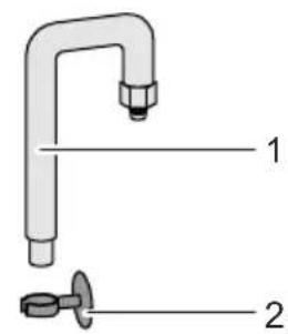
text_image
Diagram of a faucet with labeled parts, showing parts 1 and 2
text_image
3
natural_image
Simple line drawing of a cylindrical object with a labeled dimension line (no text or symbols on the object itself)AEX0002
C
text_image
1. 2. 3.AEX0010
D
text_image
1. 2.4. 3.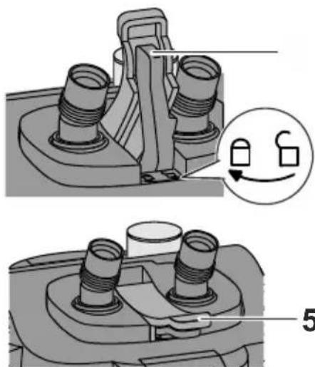
natural_image
Mechanical assembly diagram showing two views of a mechanical component with threaded ports and a close-up inset highlighting a switch mechanism (no text or symbols present)AEX0008

E
text_image
1. 2. 3. 4×AEX0003 AEX0005
F
text_image
2. 1. 4×G
natural_image
Illustration of a rectangular container with internal channels and a magnified inset showing an upward arrow inside (no text or symbols)AEX0004 AEX0007
text_image
1. 2. 3.|
text_image
1. 2. 3. 4.AEX0008
J
natural_image
Technical line drawing of a mechanical device with labeled dimension A (no text or symbols present)AEX0009
K
natural_image
Mechanical component diagram showing a fan assembly with a close-up view of the internal gear mechanism (no text or symbols present)AEX0011
L
natural_image
3D mechanical component diagram showing a fan-like structure with internal blades and mounting brackets (no text or symbols)M

text_image
1.AEX0012 AEX0013
FOR YOUR SAFETY
Read this instruction manual carefully and familiarise yourself with the filter.
Keep this instruction manual in a safe place. It is an integral part of the product.
Observe your duty of supervision
- The fter can be used by children aged 8 and above and by persons with reduced physical, sensory or mental capabilities or lack of experience and knowledge if they are supervised or have been instructed on how to use the filter in a safe way and they understand the hazards involved.
- Do not allow children to play with the filter.
- Do not allow children to carry out cleaning and user maintenance without close supervision.
Prevent electric shock
- ☐ not use the appliance if it has a damaged cord or housing.
- Only connect the appliance to a correctly installed power socket.
- Protect the plug and socket from moisture.
- Always disconnect all appliances in the aquarium from the power supply before reaching into the water.
- Switch off and disconnect plugs from the power supply in the following situations:
- Always disconnect the appliance from the power supply before carrying out cleaning or maintenance measures.
- Never make any changes to the appliance.
- Never open the motor head.
Prevent damage to property
- Do not allow the pump of the filter to run dry.
- Route cables and hoses such that they are protected and cannot cause a tripping hazard.
Observe symbols and information
Warnings

WARNING
Warns of a hazardous situation, which could lead to death or severe injuries if not avoided.
- Measures for preventing the hazard are specified here.
NOTE
Indicates a situation, which could lead to malfunctions or damage to property if not avoided.
- Measures for preventing the hazard are specified here.
Additional information

Reference to a figure, e.g. Fig. A.

Reference to another section.
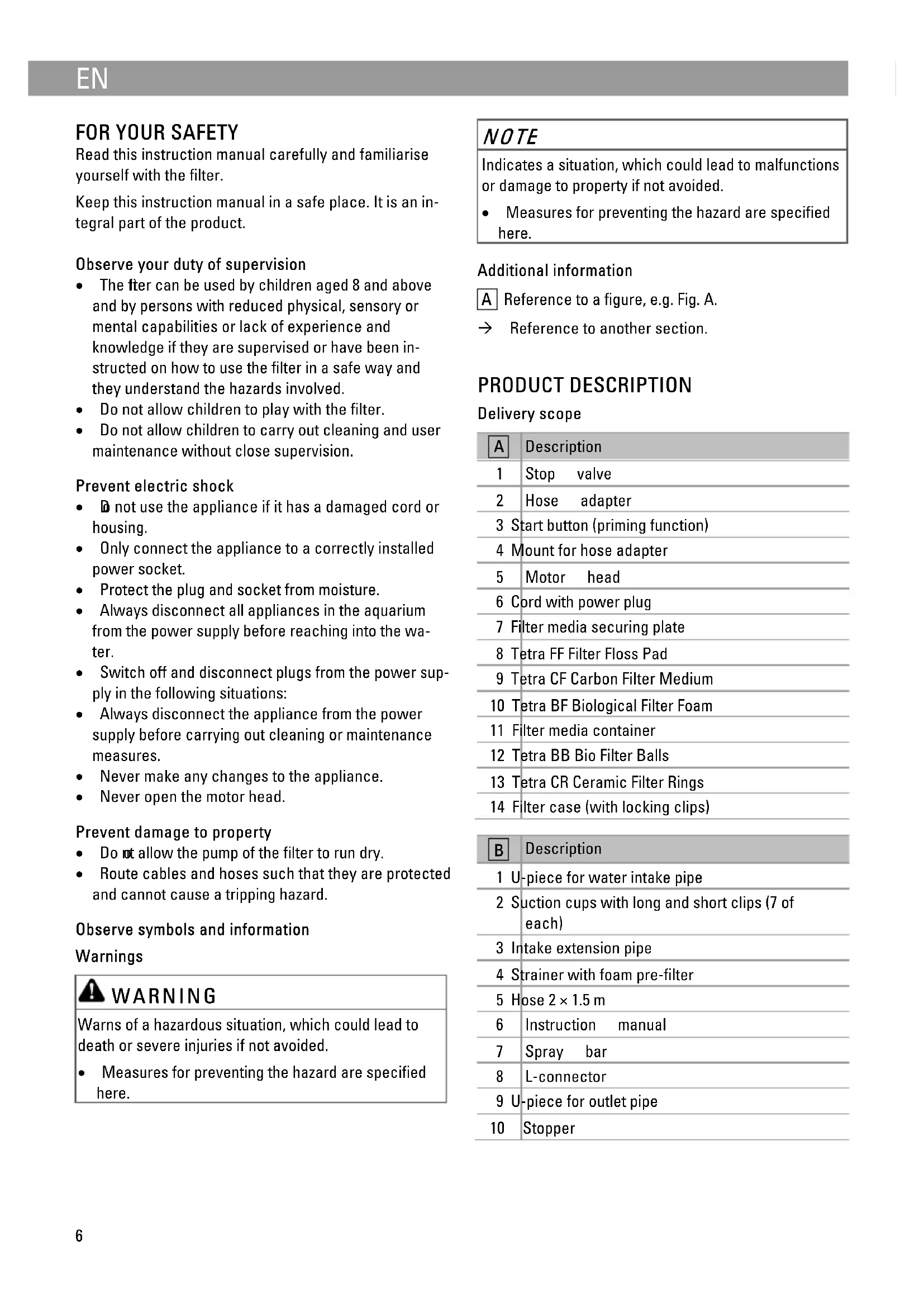
PRODUCT DESCRIPTION
Delivery scope
| A | Description |
| 1 | Stop valve |
| 2 | Hose adapter |
| 3 | Start button (priming function) |
| 4 | Mount for hose adapter |
| 5 | Motor head |
| 6 | Cord with power plug |
| 7 | Filter media securing plate |
| 8 | Tetra FF Filter Floss Pad |
| 9 | Tetra CF Carbon Filter Medium |
| 10 | Tetra BF Biological Filter Foam |
| 11 | Filter media container |
| 12 | Tetra BB Bio Filter Balls |
| 13 | Tetra CR Ceramic Filter Rings |
| 14 | Filter case (with locking clips) |
| B | Description |
| 1 | U-piece for water intake pipe |
| 2 | Suction cups with long and short clips (7 of each) |
| 3 | Intake extension pipe |
| 4 | Strainer with foam pre-filter |
| 5 | Hose 2 × 1.5 m |
| 6 | Instruction manual |
| 7 | Spray bar |
| 8 | L-connector |
| 9 | U-piece for outlet pipe |
| 10 | Stopper |
Intended use
EX 400 Plus, EX 600 Plus, EX 800 Plus, EX 1200 Plus may only be used as specified in the following:
• For cleaning aquarium water.
- For operation with freshwater or saltwater.
• Operation under observance of the technical data.
The following restrictions apply to the appliance:
- Only operate with water at a temperature of +4 °C ... +35 °C.
- Only install the appliance outside of the aquarium. Never place it into the water.
- Only use indoors.
- Only use for aquaristic purposes in the home (not for commercial use).
ACCESSING THE FILTER
Removing the hose adapter
The hose adapter is removed before taking off the motor head.
Prerequisite:
- The plug is disconnected from the power supply.
• Both stop valves are closed.
How to proceed:
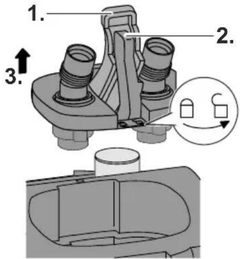
C
- Hinge up the cover on the hose adapter.
- Hinge up the locking lever and turn it as far as it goes into the position "lock open".
- Pull the hose adapter off the motor head.
Fitting the hose adapter
How to proceed:
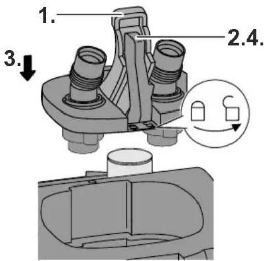
D
- Hinge up the cover on the hose adapter.
- Turn the locking lever into the position "lock open".
- Fit the hose adapter into the intended recess and press it into the motor head as far as it goes.
- Turn the locking lever into the position "lock closed" as far as it goes and hinge down.
- Hinge down the cover.
Removing the motor head
The motor head is removed for cleaning and maintenance, and for changing the filter media.
Prerequisite:
- The hose adapter has been removed. (→ Removing the hose adapter)
How to proceed:
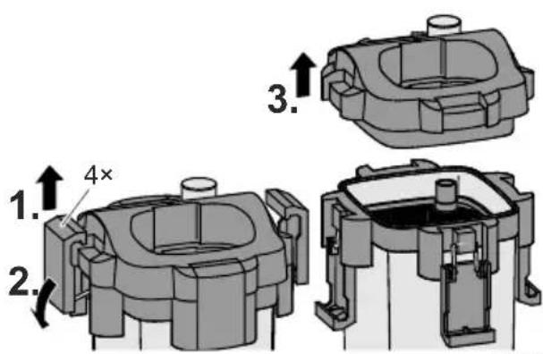
E
- Lift and release all four locking clips on the filter case.
- Hinge down the locking clips.
- Remove the motor head.
Fitting the motor head
How to proceed:
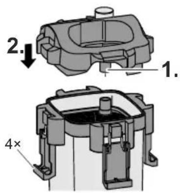
F
- Align the motor head such that the pipe is positioned over the opening of the filter media securing plate.
- Fit the motor head onto the filter case and fasten with the four locking clips.
- Fit the hose adapter. (→ Fitting the hose adapter)
INSTALLATION AND CONNECTION
Prepare the filter media
Some of the filter media is packaged on delivery. It has to be removed from the packaging and rinsed.
Prerequisite:
- The motor head has been removed. ( Removing the motor head)
How to proceed:
A
- Remove the filter media securing plate, all filter media containers and filter media from the filter case.
- Unpack the filter media, dispose of the packaging in an environmentally friendly manner.
- Thoroughly rinse all the filter media with warm tap water.
Filling the filter case with filter media
The filter case has to be filled with the filter media in the correct order.
Prerequisite:
- The motor head has been removed. (→ Removing the motor head)
- The filter media is prepared. (→ Prepare the filter media)
How to proceed:
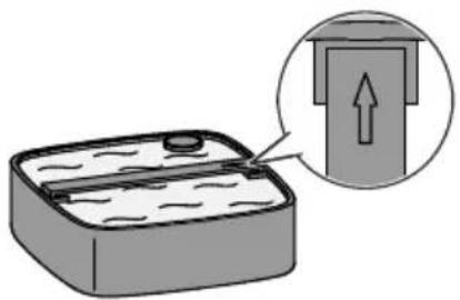
A G
- Place the filter media securing plate, filter media containers and filter media into the filter case in the correct order.
- Align the filter media securing plate and filter media containers such that the arrows point in the same direction as the arrow on the filter case.
- Close the filter ( Fitting the motor head).
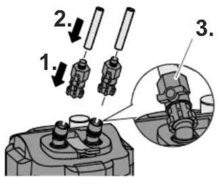
Connecting the hose to the hose adapter
The procedure is identical for the inlet IN and outlet OUT.
How to proceed:
H
- Fit the stop valve onto the hose adapter connection and turn the nut clockwise by hand.
- Fit the hose onto the hose connection socket.
- Turn the union nut for securing the hose counterclockwise.
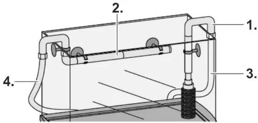
Fitting the intake pipe and outlet pipe
How to proceed:
B I
- Assemble the intake pipe as shown and fasten it with the suction cups vertically to the inside wall of the aquarium,
- Assemble the outlet pipe as shown and fasten it with the suction cups horizontally above the surface of the water to the inside wall of the aquarium, - Shorten the outlet pipe if necessary.
- Connect the hose from the inlet IN of the filter to the intake pipe.
- Connect the hose from the outlet OUT of the filter to the outlet pipe.
NOTE
Kinks or twists in the hose impair the function of the filter.
- Route the hose without kinks and twists.
• Shorten the hose if necessary.
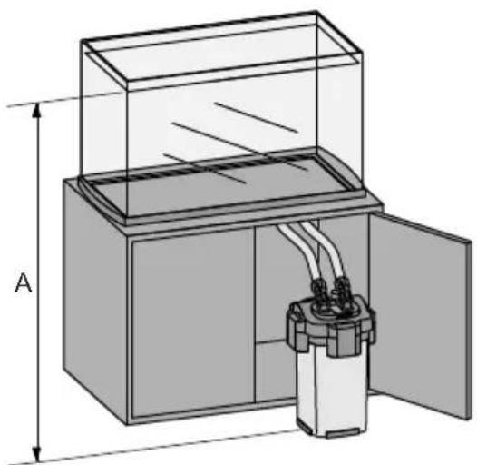
Positioning the filter
J
Position the filter at the specified distance from the level of the water in the aquarium to avoid malfunctions of the filter.
| Filter Distance A | |
| EX 400 Plus 40 ... 150 cm | |
| EX 600 Plus 50 ... 150 cm | |
| EX 800 Plus 60 ... 150 cm | |
| EX 1200 Plus 80 ... 150 cm |
START-UP
!
WARNING
Dangerous electrical voltage!
Death or severe injury from electrocution.
- Only connect the plug to a correctly installed power socket.
- Never connect the plug to the power socket if the filter, hoses, cord or plug are damaged.
NOTE
The pump must never run dry. The pump will be destroyed.
- Regularly check the water level and circulation in the filter and in the aquarium.
NOTE
Risk of water damage due to leaking hoses.
- Immediately check all hoses and connections for leaks after starting up the filter.
- If there are any leaks, immediately disconnect the plug and close the stop valves.
- Do not start up the filter again until all leaks have been eliminated.
- Check for leaks again when the filter has been operating for approx. 30 minutes.
How to proceed:
- Completely open the stop valves at the inlet IN and outlet OUT.
- Press the start button several times in quick succession until the filter starts filling with water.
-
Wait until water is visible in the hose to the outlet pipe.
-
Connect the plug of the filter to the power socket.
-
The pump in the motor head will switch on automatically.
- Set the flow rate.
- Set the desired flow rate with the stop valve at the inlet IN.
- The stop valve at the outlet OUT remains completely open.
CLEANING AND MAINTENANCE

WARNING
Dangerous electrical voltage! Death or severe injury from electrocution.
- Switch off the appliance, disconnect the power plug and secure the appliance from being switched on again before starting any work.
- After completing all work, restore all prerequisites for start-up.
Maintenance intervals
| Components | Inspection | Cleaning | Replacement |
| Tetra FF Filter Floss Pad — — | Monthly | ||
| Tetra CF Carbon Filter Medium | — — Every 2 to 4 weeks | ||
| Tetra BB Bio Filter Balls Every 12 months In the event of an obstruction due to extreme soiling | If the dirt on the surface cannot be removed by rinsing | ||
| Tetra BF Biological Filter Foam | Every 6 months When dirt is visible on inspection | Every 12 months | |
| Tetra CR Ceramic Filter Rings | Every 12 months In the event of an obstruction due to extreme soiling | If the dirt on the surface cannot be removed by rinsing | |
| Impeller — If the motor is not working | or the water flow is reduced | — | |
Cleaning/replacing the filter media
- Do not use cleaning agents or chemical solutions.
- If there are several foam filters, clean or replace the foam filters at different times. This saves enough useful bacteria to ensure good biological filtration of the water.
NOTE
Normal tap water destroys the bacteria colonies in the filter media. This will impair the cleaning effect.
- Only use water from the aquarium for cleaning the filter media.
Prerequisite:
- The motor head has been removed. ( Removing the motor head)
How to proceed:
- Remo ve all filter media from the filter case.
- Carefully clean the filter balls, foam filters and ceramic filter rings with water from the aquarium.
- Change the filter media according to the change intervals.
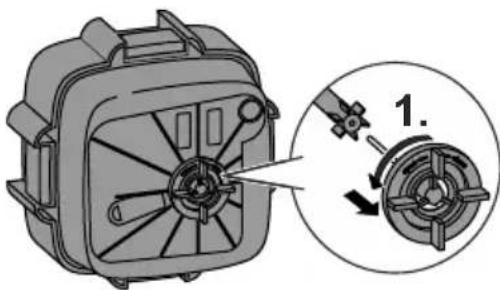
Cleaning/replacing the impeller
Prerequisite:
- The motor head has been removed. (→ Removing the motor head)
How to proceed:
K
- Turn the cover cap counter-clockwise into the position "open" and remove.
- Clean the cover cap and impeller with warm tap water.
-
Replace damaged parts.
-
Assemble the parts in the reverse order.
-
Turn the cover cap clockwise into the position "close".
Cleaning/replacing the motor head seal
Prerequisite:
- The motor head has been removed. ( Removing the motor head)
How to proceed:
L
- Remove the motor head seal and clean with warm tap water.
- Replace the motor head seal if damaged.
- Fit the motor head seal.
- Ensure that the motor head seal fits tightly to the motor head all the way round.
Cleaning the foam pre-filter
The foam pre-filter has to be cleaned if it is heavily soiled.
How to proceed:
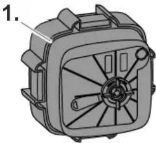
M
- Pull the foam pre-filter from the strainer and wash with clear, warm water.
STORAGE
How to proceed:
- Disconnect the power plug.
- Empty the water from the filter, clean the filter and filter media. ( Cleaning and maintenance)
- Store the filter in a dry place.
DISPOSAL
NOTE

Incorrect disposal causes damage to the environment.
- Dispose of the packaging materials in an environmentally friendly way in accordance with the applicable legal regulations.
- Render the filter unusable beforehand by cutting the cord and dispose of the filter via the return system provided for this purpose.
TROUBLESHOOTING
| Malfunction Possible cause Remedy | ||
| The motor head cannot be fastened to the filter case. | The arrows on the filter media container and on the filter case are not all pointing in the same direction. The filter media containers are incorrectly fitted. | Fit the filter media containers correctly. |
| Too much filter media has been put into the filter media containers. | Remove excess filter media. | |
| Water leakage from the motor head. | The locking clips are not properly closed. Close the locking clips properly. | |
| Dirt or foreign bodies are located on the filter case or motor head seal. | Clean all points where the motor head seal and filter case make contact. | |
| The motor head seal is incorrectly fitted, damaged or missing. | Correctly insert the motor head seal or replace. | |
| The edge of the motor head is damaged. Replace the motor head. | ||
| The hose adapter is incorrectly fitted. Fit the hose adapter correctly. | ||
| The motor is not working. | The power supply is interrupted. Establish the power supply. | |
| The impeller shaft is broken. Replace the impeller. | ||
| The impeller is missing or is blocked by foreign bodies. | Fit the impeller or clean. | |
| Reduced water flow. The hose adapter is heavily soiled. Remove the hose adapter and clean with warm water. | ||
| Air trapped in the filter. | Insufficient distance between the filter and the water level in the aquarium. | Position the top edge of the filter head at least 10 cm below the level of the water. |
| Filter media clogged. Clean the filter media. | ||
| Air entering through the intake pipe. | • Route a hose between the intake pipe and filter below the level of the water in the aquarium.• Renew the O-ring on the intake pipe. | |
| The filter does not start up correctly. | Filter media insufficiently cleaned. Clean the filter media. | |
| The filter media is contained in nets. Do not use filter media in nets or nylons as the filter will become clogged. | ||
| Unusual noises emitted when the filter starts up. | Air is entering through the hose connection. | Connect the hoses properly. |
| Air trapped in the filter. Carefully shake the filter to allow the air to escape. | ||
| Unusual noises emitted from the filter during operation | Foam pre-filter clogged. Clean the foam pre-filter. | |
| Insufficient flow rate Open the stop valves to increase the flow rate. | ||
| Insufficient lubrication of the O-rings. Apply a generous amount of commercially available lubricant such as Vaseline to the O-rings. | ||
| Uneven water circulation due to insufficient intake of water. | Disconnect and reconnect the power plug to start up the filter again. | |
| Insufficient distance between the filter and the water level in the aquarium. | Position the top edge of the filter head at least 10 cm below the level of the water. | |
| Air trapped in the filter. Carefully shake the filter to allow the air to escape. | ||
| There is a sound of air being emitted from the outlet pipe about every 10 seconds. | Air released by aquatic plants during photosynthesis and by bacteria causes the formation of air bubbles, which cause this sound. No measures necessary. | |
| The start button is pressed. Never press the start button when the filter is operating.Ensure that no objects accidentally press against the start button. | ||
TECHNICAL DATA
| Description EX 400 Plus EX 600 Plus EX 800 Plus EX 1200 Plus | ||||||
| Rated voltage V AC 230 | ||||||
| Rated frequency Hz 50 | ||||||
| Power consumption W 5.5 7.5 10.5 19.5 | ||||||
| Flow rate during operation without filter media and hose | l/h | 450 | 630 | 790 | 1300 | |
| Flow rate during operation l/h 320 360 | 430 810 | |||||
| Suitable tank size l | 10-80 | 60-120 | 100-300 | 200-500 | ||
| Filter capacity | l | 3.2 5.7 6.6 12.0 | ||||
| Number of filter media containers | 2 | 3 | 4 | 4 | ||
| Hose internal diameter | mm | 12 | 12 | 12 | 16 | |
| Dimensions | Length | mm | 211.6 | 211.6 | 211.6 | 263.2 |
| Width | mm | 211.6 | 211.6 | 211.6 | 263.2 | |
| Height | mm | 314.0 | 364.0 | 412.0 | 495.1 | |
| Length of the connection cord | m | 1.65 | ||||
GUARANTEE
Tetra gives a three year guarantee from the date of purchase. Please keep proof of purchase. The guarantee does not cover improper use, normal wear and tear or modifications to the appliance. In the event of a complaint please contact your local retailer or Tetra GmbH, Tetra Technik Service Center, Postfach 1580, D-49304 Melle, Germany.