USER MANUAL Connect FERROLI
Installation and Use Manual
- Introduction 32
- General safety rules 32
- Control class according to ErP regulations 32
- For the installer 33
4.1 Contents 33
4.2 Installing the receiver 34
4.3 Thermostat installation 36
4.4 Thermostat support assembly 37
- For the end user 38
5.1 Buttons and Icons 38
5.2 Functional diagram 40
5.3 System configuration 41
5.3.1 Creating the account 41
5.4 RF configuration (Receiver - Thermostat) 41
5.5 Wi-Fi configuration (Receiver-Router) 42
5.6 APP CONNECT 43
5.6.1 Manual mode 46
5.6.2 Weekly programming mode 47
5.6.3 Vacation mode 51
5.6.4 Thermostat mode off 51
5.7 Thermostat 52
5.7.1 Basic operations 52
5.8 Compensation with outside temperature.. 56
5.9 Receiver 57
- Technical specifications 58
1. INTRODUCTION
Dear customer, thank you for choosing the CONNECT smart thermostat.
It will allow you to accurately control the room temperature and, thanks to Wi-Fi connectivity, can be controlled remotely via the dedicated APP.
This manual is intended for installers and end users.
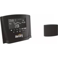
The main component of the system is the programmable thermostat that can manage the time programs set by the APP, measure the zone temperature and send on/off commands to the remote control unit, connected directly to the boiler.
2. GENERAL SAFETY RULES
- Read the instructions in this manual carefully
- After installation, inform the user about the device's functions, and giving the user this booklet to be kept carefully as an integral part of the product and subsequently used for future reference
- Installation and maintenance must be carried out by qualified personnel, according to the rules in force and the manufacturer's instructions. Do not perform any operation on the sealed control parts.
- Remove the electrical power supply before cleaning.
- Do not place the device near heat sources.
- Keep out of the reach of children
3. CONTROL CLASS ACCORDING TO ERP REGULATIONS
With reference to the applicable regulation (EU) No. 811/2013, the data shown in the table can be used to complete the labeling of heating units.
Possible combinations with CONNECT, related configuration classes and energy contribution to the system.
| Boiler type | CONNECT | Class and contribution |
| Boiler with fixed flow temperature (On-Off) | On-Off type I = 1% | |
| Boiler with variable flow temperature (set point with communication bus) | Connection via communication bus. Flow set point calculated according to the room and outdoor temperature. | VI = 4% |
| Connection via communication bus. Flow set point calculated according to at least 3 different ambient temperatures (at least 3 thermostats and 3 zone valves required) | VIII = 5% |
4. FOR THE INSTALLER
4.1 Contents
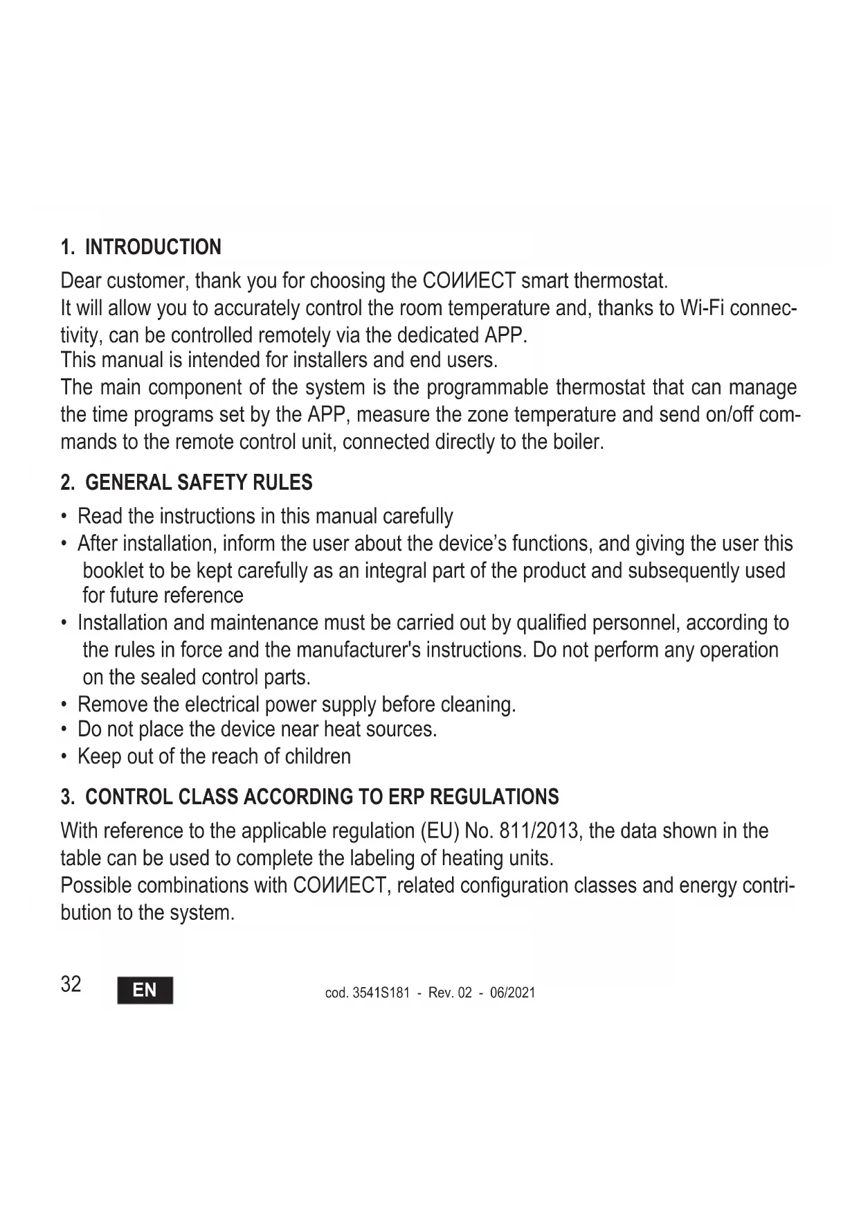
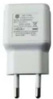
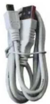
The box includes the following parts:

Transmitter programmable thermostat

Receiver

Manual
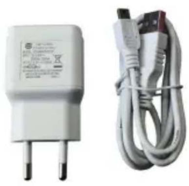
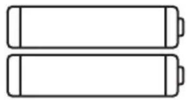

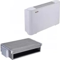
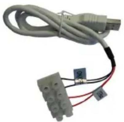
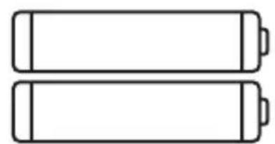
USB cable Power supply AAA type batteries

Table support Accessories
4.2 Installing the receiver
ATTENTION: To protect the device, remove the power supply from the boiler before making the connection. The operation must be carried out by qualified personnel.
The receiver can work with the OpenTherm protocol or with the On-Off contact.
Use the magnetic plate or the double-sided adhesive (supplied with the accessories) to place the receiver in the best position according to the quality of the surface, or use the screws to secure it directly to the wall.
The gateway must be installed inside the building and should not be shielded by any metal enclosures.
OpenTherm option (A fig. 1): Connect the two red wires with label OTBus, coming from the receiver, to the boiler where the OpenTherm connection is foreseen. Leave the other two wires disconnected. In this case, more information is available on boiler status (see "5.7.1 Basic operations" on page 52).
On-Off option (B fig. 1): Connect the two black wires with label ON/OFF, coming from the receiver, to the boiler where the connection to the ON/OFF thermostat is foreseen. Leave the other two wires disconnected.
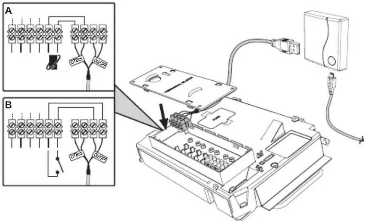
fig.1
Once powered, the LEDs flash briefly.
4.3 Thermostat installation
Separate CONNECT from the base fig. 2.
Secure the base using the screws provided fig. 3.
In case of thermostat directly connected to the boiler or to a zone valve, the cables must be connected in the appropriate terminal fig. 4.
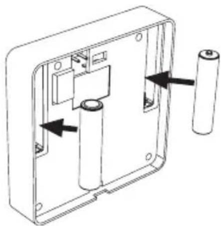
Insert two 1.5V AAA batteries fig. 5.
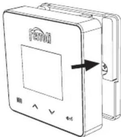
Hook CONNECT on the base fig. 6.
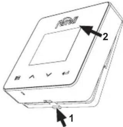
fig. 2
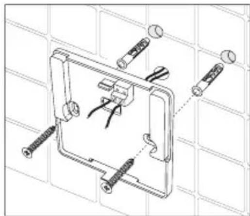
fig. 3
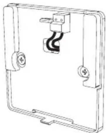
fig.4 fig.5 fig.6
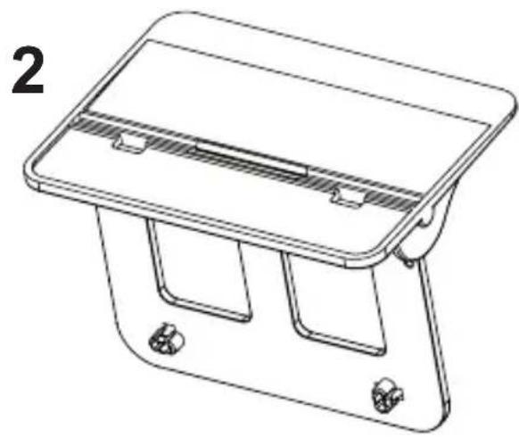
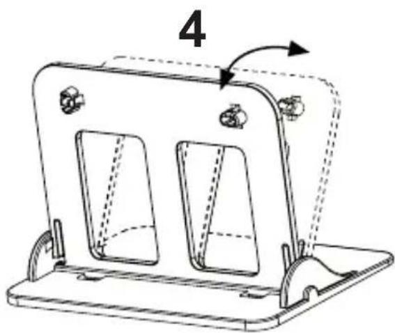
4.4 Thermostat support assembly
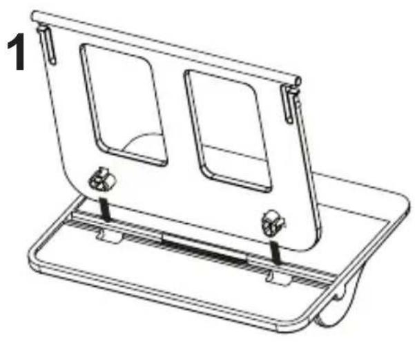

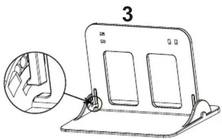

fig. 7 - Thermostat support
5. FOR THE END USER
A description of the symbols on the display and the meaning of the buttons is given below.


fig. 8
| Icon Description |
| Heating |
| DHW (domestic hot water) |
| Heat demand |
| OFF |
| AUTO mode |
| MANUAL mode |
| VACATION mode |
| Icon Description |
| RF connection |
| WiFi connection |
| Low battery level |
| 88:88 | Temperature and time |
| mode/save/exit |
| increase |
| decrease |
| set |
| ○ | LED button |
Battery: The icon on the screen is activated when the battery level is too low.
Flame
» Thermostat connected to an on-off boiler, the icon indicates request status.
» Thermostat connected to an OpenTherm boiler, the icon indicates burner status.
Note: At first activation the thermostat is configured automatically in On-Off wire connection mode.
When the thermostat and the WiFi receiver are connected to the wireless network, the thermostat automatically switches to RF On-Off mode.
When the WiFi receiver is connected to an OpenTherm boiler, the thermostat automatically switches to RF OpenTherm mode.
If the thermostat has been configured as RF (on-off or OpenTherm) it does not automatically switch to On-Off wire mode. This can only be done by removing and putting back the batteries.
DHW: the icon indicates that DHW is on.
Note: The icon is only present in the case of RF connection with OpenTherm boilers.
Heating: the icon indicates that heating is active.
Note: The icon is only present in the case of RF connection with OpenTherm boilers.
Temperature: the room temperature or errors are displayed:
E82: RF communication error
E83: OpenTherm communication error

5.2 Functional diagram
fig.9
5.3 System configuration
To allow proper operation with your device (Tablet or smartphone), proceed as follows:
- Download the App (CONNECT) directly from the App Store of your device or using the QR CODE on the outside of the package.
- After installation, create the account.
5.3.1 Creating the account
- Make sure your SMARTPHONE/TABLET device is connected to the Wifi network.
- Open the dedicated APP, and click on "Register".
- Enter the requested data and press code verification.
- To confirm the registration, enter the code received via the email previously entered. To manage the boiler from several users, enter with the same account.
5.4 RF configuration (Receiver - Thermostat)
To establish the RF connection between the thermostat and the receiver, proceed as follows:
- Press the receiver LED button until it flashes (about 7 seconds).
- In the thermostat keep the "set" ← button pressed for a few seconds until the display flashes.
- Press the button until displaying and press "set".
- When the message "r01, r02..÷..r08" appears, the connection has been made. Press "set" again.
Note: Data exchange between thermostat and receiver occurs within 2 minutes
5.5 Wi-Fi configuration (Receiver-Router)
Connect with your Smartphone / Tablet device to the local WiFi network.
- Click "+" and enter the local network password
Press "next"
- In the receiver, briefly press the WPS button with a dedicated tool
Press "next"
- Follow the APP instructions
If the procedure was unsuccessful:
- Check the WiFi connection of the mobile device (the configuration must be done with WiFi)
- Check the router, restart the mobile device and repeat the operations
5.6 APP CONNECT
On the main screen (fig. 10), press where indicated to access control of one of the configured boilers.
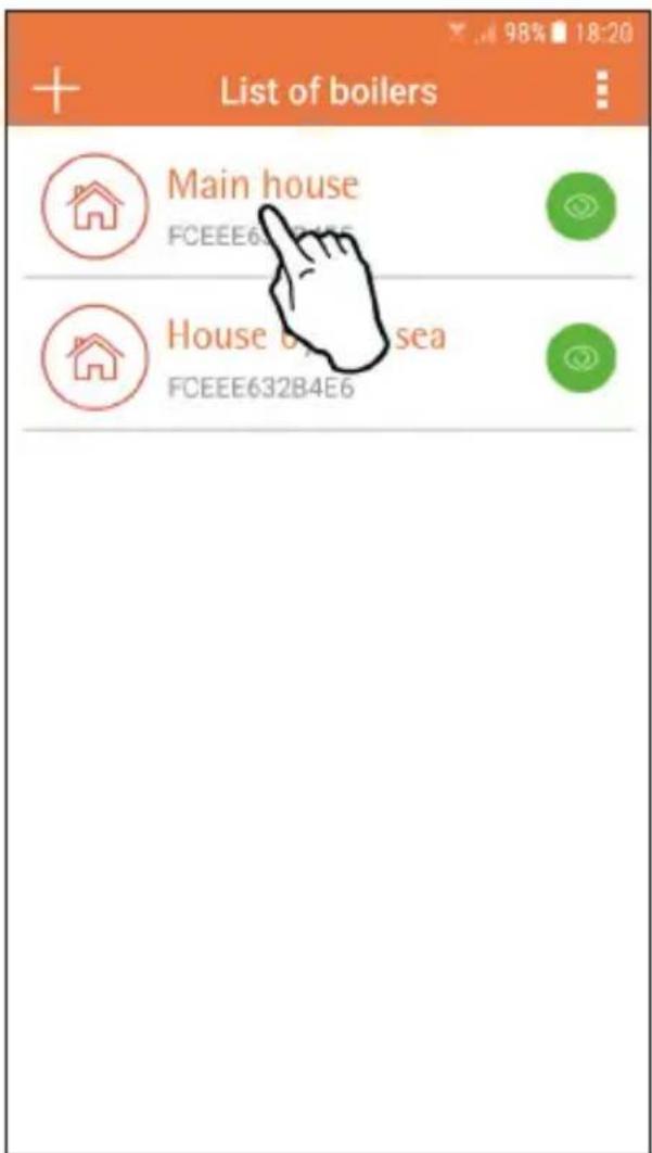
fig. 10 - Main screen
On the next screen (fig. 11) press A to manage room temperature control or press B to display boiler status.
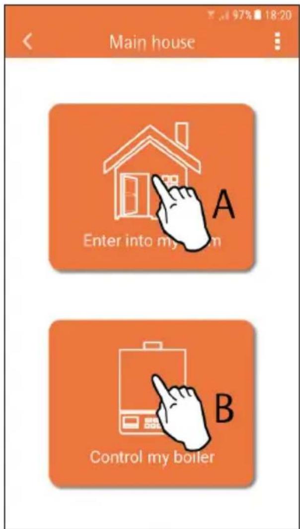
fig. 11 -

The connected remote timer control setting can be accessed on this screen.
If there are several zones, select the one required.
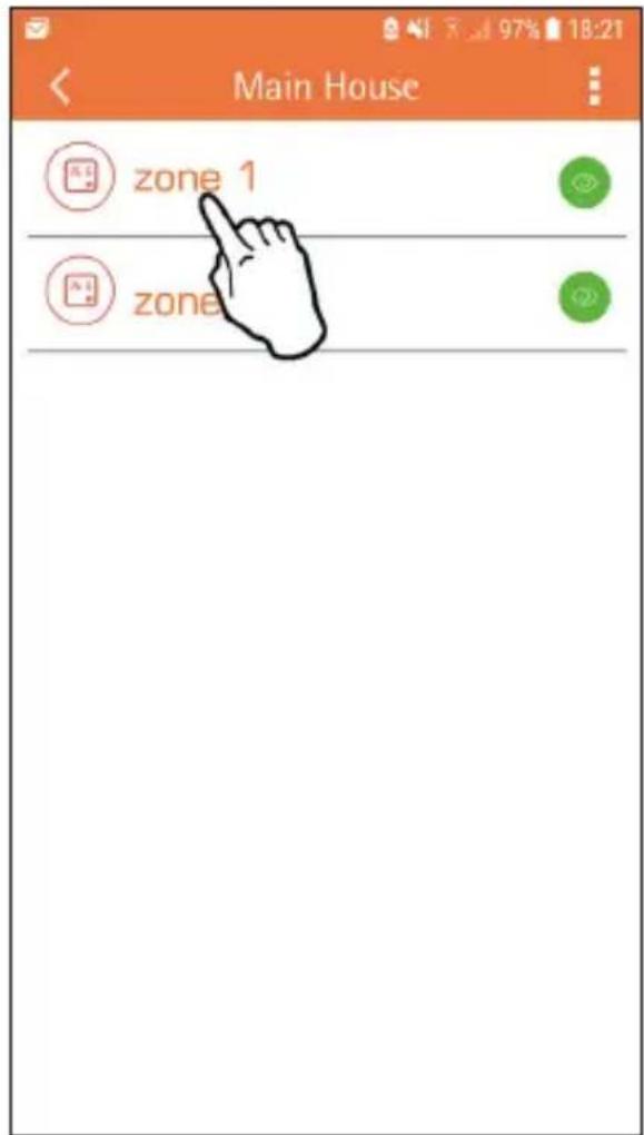
fig. 12 - Remote Timer Control
The possible modes are:

Manual mode

Weekly programming

Vacation mode

Thermostat
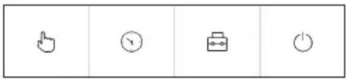
fig. 13 - Possible modes

On this screen (fig. 14), if the boiler is connected via OpenTherm protocol, it is possible to display its status. Also, by clicking on the symbols , the boiler DHW and heating set points can be changed.
If the boiler is connected via On-Off contact, only the status of the request is displayed (fig. 15).
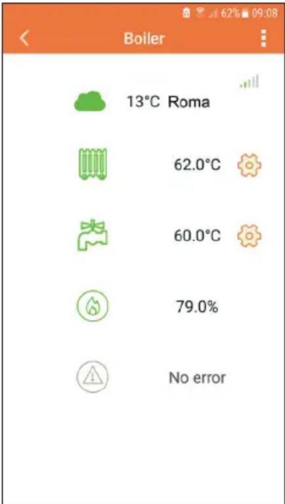
fig. 14 - With OpenTherm
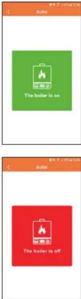
fig. 15 With room thermostat

5.6.1 Manual mode
The desired room temperature can be set in this mode.
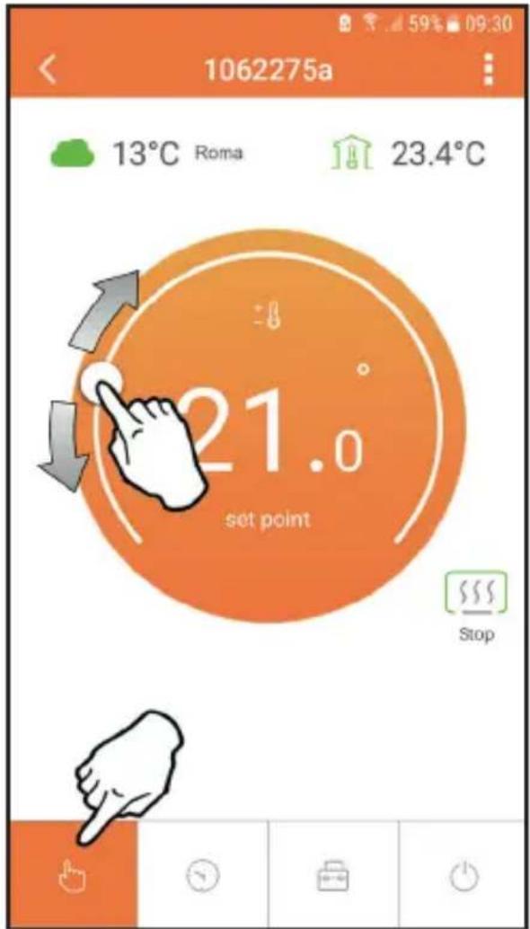
fig. 16
5.6.2 Weekly programming mode
In this mode the desired temperature for the various time slots of all days of the week can be set by pressing where (B) indicated in fig. 17.
It is also possible to temporarily change the desired temperature (until the next time slot) by acting on point "A", without modifying the program.
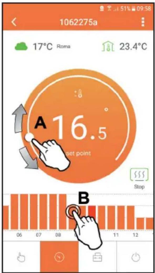
fig. 17
3 temperature levels are available: T3 (COMFORT 1), T2 (COMFORT 2) and T1 (ECO). To set the temperature of levels T1, T2 and T3, follow the sequence given below.
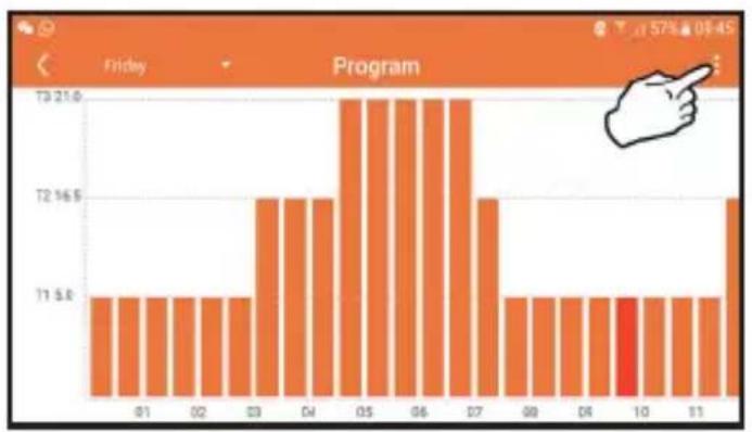
fig.18
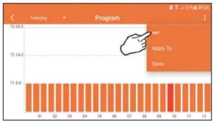
fig. 19
Set the temperatures and confirm.
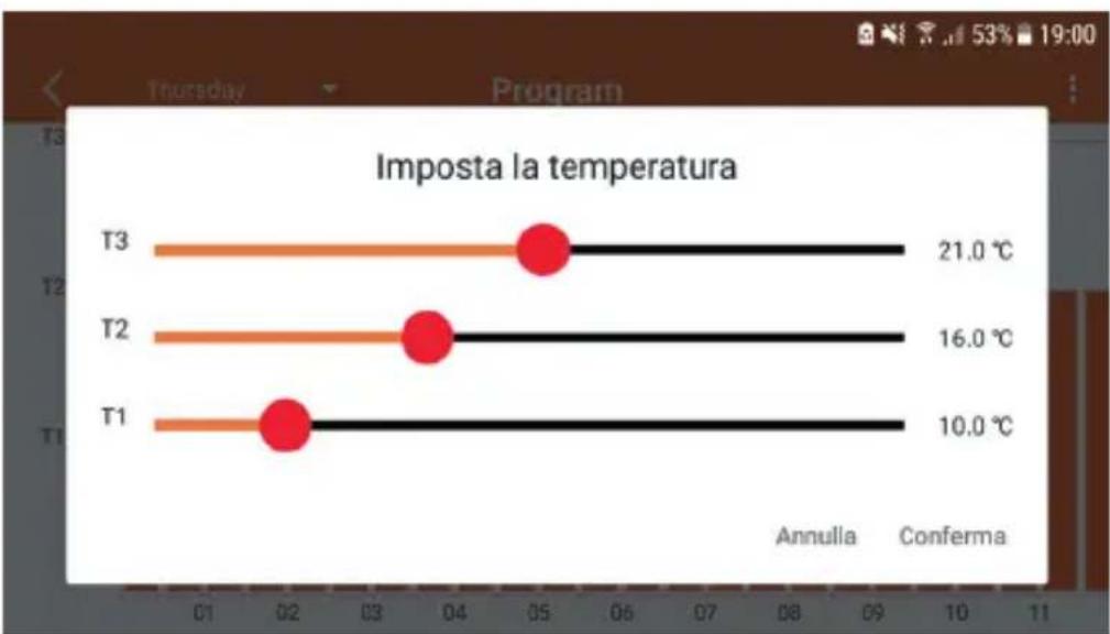
fig. 20 Setting temperatures
To change the time slots, press in the area to be changed.
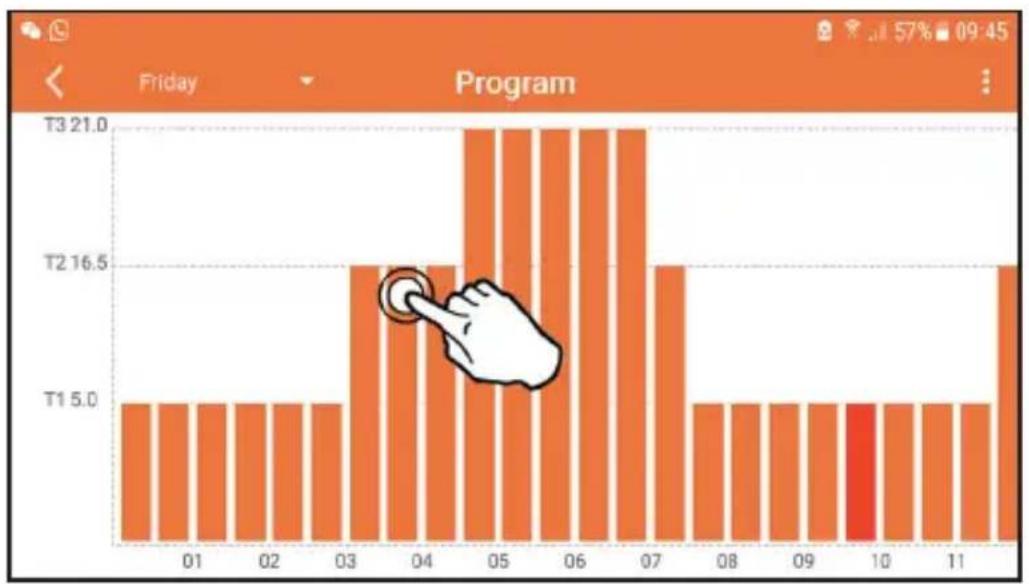
fig. 21
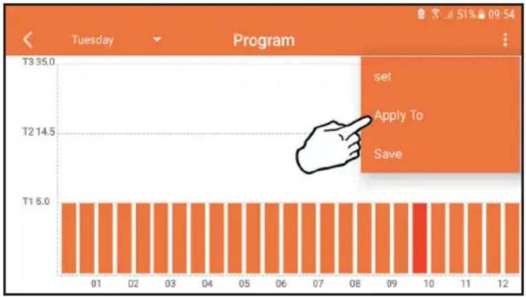
After programming the temperatures, save the configuration.
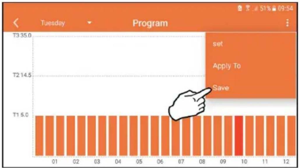
fig. 22
Click "apply" to select the days in which to copy the settings just made.
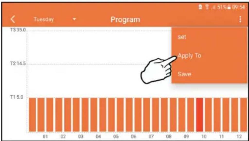
fig. 23
If the outside temperature information is available (via WEB or OpenTherm), the temperature set in the boiler takes this value into account to adjust the flow. If the outside temperature is not available, the flow is adjusted according to the set room temperature.
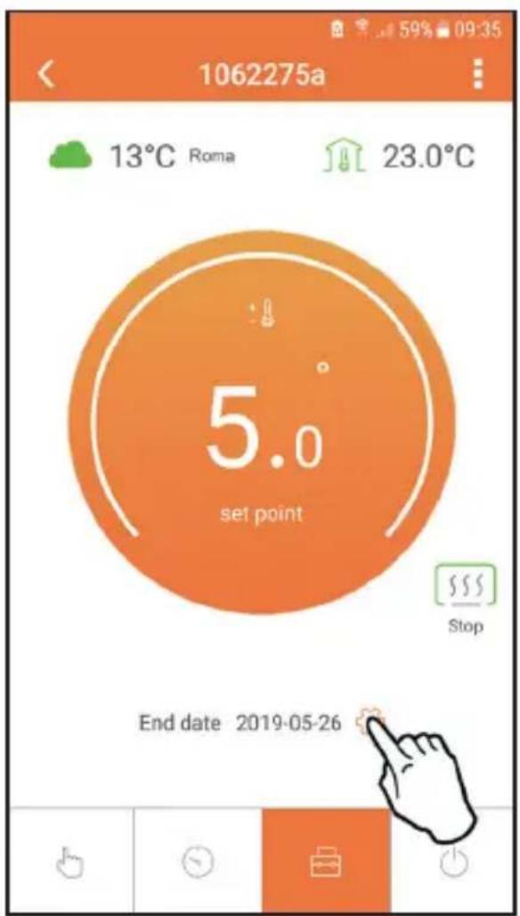
5.6.3 Vacation mode
In this mode, the boiler is switched off and will be reactivated if the temperature goes below the indicated set point.
The vacation end date can be set by pressing the setting icon
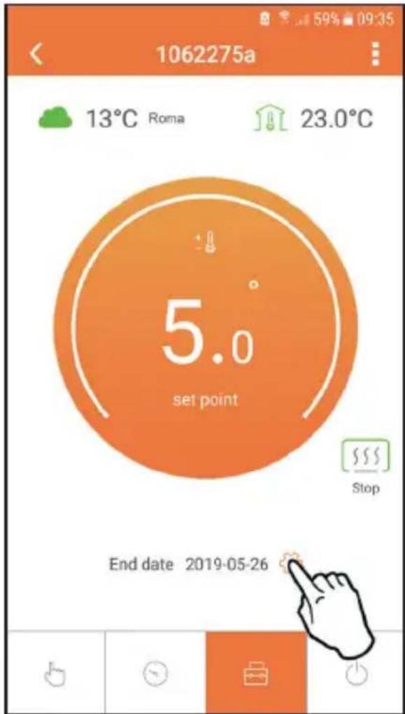
fig. 24
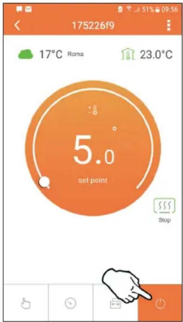
5.6.4 Thermostat mode off
In this mode the boiler is switched off and will be reactivated if the temperature drops below 5^ .
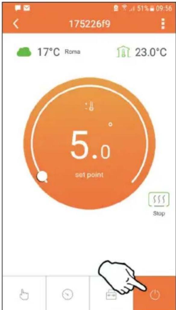
fig. 25
5.7 Thermostat
5.7.1 Basic operations
- Press the "mode" button to switch between the various modes:
a. Off : in this mode the heat request is disabled; only the frost protection mode remains active.
b. Vacation : the set temperature is that of frost protection energy saving for a number of days set via the buttons
c. Automatic + : the required temperature is that of the weekly program set via APP. If the program has not been set, the system default one is used.
d. Manual the temperature is set manually, directly on the thermostat.
- Temperature setting:
a. Manual: press the buttons

- Settings menu: press "set" for about 2 seconds to access the settings menu.
a. “and” scroll the menu
b. "set" <access the selected parameter
c. "mode": return to the main menu
- In case of a boiler fault, the error code is also shown on the thermostat display. It is possible to reset the fault via the "set" button.
For a description of the fault, refer to the boiler handbook.
| No. Parameter Display description | |
| 1) Clock | 14:05 | Set hours, minutes, year (y), month (m), day (d). |
| 2) Temperature | 23.0°C | Set the temperature of CFT1, CFT2, ECO, FRST |
| 3) COUP code | COUP | RF code (see par. 5.4 on page 41) |
| 4) DHW set point | dHUJ | Set DHW temperature, function available only with OpenTherm connection |
| 5) Boiler information | nFO | Reading of some boiler parameters only with OpenTherm connection |
| 6) Installer data | PL | Installer parameters |
| 7) Exit | EHI E | Return to the home page |
1)Clock
Press the buttons and to select the clock menu, and then "set" to enter.
Press the "set" button to select the data to be changed with this sequence: hour, minutes, year, month, day.
Press the buttons and to change the value.
Press "mode": go back.
2) Temperature
Press the buttons and to select the temperature menu, and then "set" to enter.
»Press the buttons and to select the temperatures to be changed:
» comfort (CFE) - economic (ECO) - frost protection (FRF)
Press the buttons and to change the value of the selected temperature.
Press "set" or "mode" to return to the previous menu.
3) Coupling code
»See par. 5.4 on page 41.
4) DHW temperatures (OpenTherm boilers only)
Press the buttons to select the DHW temperature, and then "set" to enter.
Press the buttons to change the value.
Press "set" or "mode": to return to the previous menu.
Note: If the thermostat receives the data from the boiler, then it displays this value, otherwise the setting range is 30 - 60^ .
Press the buttons to select information, and then "set" to enter.
»When “- - - ” is displayed, it means the data is not available in the boiler
Press "set" or "mode": return to the previous menu.
| No. information |
| 1 Flow set point |
| 2 Flow probe |
| 3 Return probe |
| 4 DHW temperature |
| 5 Outside temperature |
| 6 Power percentage |
| 7 DHW draw |
| 8 System pressure |
6) Advanced settings (PL)
»Installer parameters
Press the buttons to select the "PL" menu, and then "set" to access.
Scroll using the buttons , until reaching the value "PS 10" then press "set" . Select the parameter to be modified (see table below) using the buttons and press "set" . Modify the selected parameter using the buttons then press "set" to confirm the change.
Press "set" or "mode" to return to the previous menu.
| Param | Description Step Unit Default | | | Range | |
| CALI | Room sensor calibration | 0.1 °C | Room temperature | -7.0 + 7.0°C | |
| FAct | Factory reset | | --- NO | NO | - YES |
| HOn | Hysteresis ON (*) | 0.1 °C | 0.4 | 0.0 ÷ 2 | 0 |
| HOF | Hysteresis OFF (**) | 0.1 °C | 0.1 | 0.0 ÷ 2 | 0 |
| bHLc | Display illumination duration | 08 | 03 ÷ 15 |
| HHCH | Flow max set point (*** ) | 1 | °C | 85 | 45 ÷ 85°C |
| LLCH | Flow min set point (*** ) | 1 | °C | 30 | 10 - HHCH |
| CLI | Climate curve (*** ) | | --- 1.2 | | 0.0, 0.2, 0.4, 0.6, 0.8, 1.0, 1.2, 1.5, 2.0, 2.5, 3.0 |
| HHbG | Boiler CH set point (*** ) | 1 | °C | 85°C | 30 ÷ 85°C |
| EHIE | Exit | | | | |
() the request is activated if T. amb < Tset -HOn
(^) the request is deactivated if T.amb > Tset + HOf
(^*) only with OpenTherm connection
7) Exit
Press "set" 一 to return to the main menu.
5.8 Compensation with outside temperature.
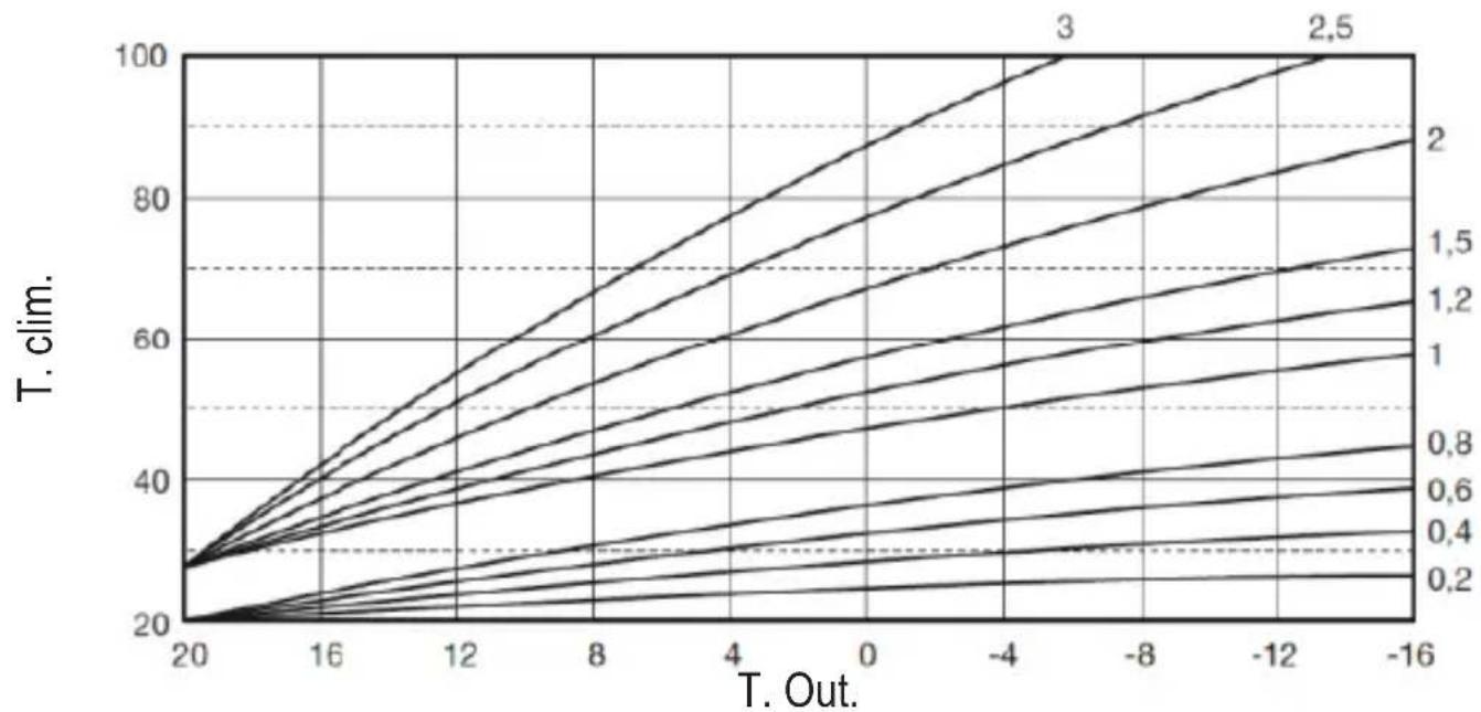
Thanks to the outside temperature (via the WEB or connected to the boiler) the thermostat calculates the boiler flow temperature, optimizing consumption. By acting on the parameter CLI (see installer menu PL), the contribution is adjusted according to the formula:
$$
\text {T f l o w} = \text {T c l i m} + 1 0 \times \text {C L I} \times (\text {T 3 - T 4})
$$
To disable the external probe, set CLI = 0 , which gives:
$$
\mathrm {T f l o w} = \mathrm {L L C H} + 1 0 \times (\mathrm {T 3} - \mathrm {T 4})
$$
T3 = room set point
T4 = room temp
T clim = see chart
LLCH = see installer menu PL
5.9 Receiver
The receiver unit allows data exchange between the thermostat and the boiler. A button with coloured LEDs indicates system status.
| Green LED | Red LED | DESCRIPTION |
| Slow blinking Sow blinking | | → | | → | → | |
| ON Slow blinking | | → | | → | → | |
| ON OFF | | → | | → | → | |
| Fast blinking OFF | | → | | WiFi connection in progress |
| OFF Fast binking | | → | | RF connection in progress |
6. TECHNICAL SPECIFICATIONS
| Electrical/ mechanical | Power supply 100 ~ 240Vac, 50 / 60 Hz |
| Consumption 1.2W | |
| Relay output Voltage-free - 0.25A | - 230Vac, 2A - 30Vdc |
| Thermostat 90 x 90 x 22 | |
| Receiver 86 x 86 x 21 | |
| Colour Black + silver | |
| Casing material ABS + aluminium | |
| Temperature sensor built-in | |
| Wi-Fi | Wi-Fi standard 802.11 b/g/n | |
| Wi-Fi frequency 2.412 GHz – 2.484 GHz |
| RF frequency 868 MHz [FSK] | |
| RF distance max 40m in free field | (*) |
| Antenna built-in | |
| Safety WEP / WPA - PSK / WPA2 - | PSK |
| Protocol | IPv4, TCP |
| Network type | STA |
(*) Any obstacles or walls can reduce the WiFi signal range. In this case, bring the gateway closer to the router, or use a WiFi extender.
cod.3541S181 - Rev.02-06/2021
$$
T i d a = T c l i m + 1 0 \times C L I x (T 3 - T 4)
$$
Para deshabilitar la sonda externa, configure CLI = 0 ; en este caso se obtiene:
$$
T i d a = L L C H + 1 0 \times (T 3 - T 4)
$$
T3 = valor de consigna ambiente
T4 = temperatura ambiente
cod.3541S181 - Rev.02-06/2021
$$
T t u r = T c l i m + 1 0 \times C L I \times (T 3 - T 4)
$$
Pentru adezactiva sonda externa, seta CLI = 0 , in acest caz vei avea:
$$
T t u r = L L C H + 1 0 \times (T 3 - T 4)
$$
| LED
Verde | LED
Rosu | DESCRIERE |
| Intermitent lent | Intermitent lent | | | | | |
| ON Intemitant lent | | | | | | |
| ON OFF | | | | | | |
| Intermitent
rapid | OFF | | | | Conexiune WiFi in curs |
| OFF | Intermitent
rapid | | | | Conexiune RF in curs |
- SPECIFICATI TEHNICE
2. OBUNI INPABUNIATEXHNI B3ONACHOCTN
BHHMaTeIbHo npOHTaIe nHcTpkyKznn, npNBedeHHbIe B 3TOM pyKOBoDCTBe.
- После установки позиформіріte пььзов {@гі O рункіноаьньх BO3MOXHOC'Tx
- устор CTBA n OCTaБTE emy эTO руковдъв Дябержнохрапень в качесъ
- HeOTbEMЛМоМоч actи n3ДeПИЯ n obpaценья 3a спразвков B byduzem.
- MoNTaJ N TexHnueckoe 06CnyKuBaHne DoJXHbI BblONHrTbcra ONbITHbIM N KBaJIINpOBAHHbIM NepCOHaJOM B COOTBcTCTBm C DeJCTByUcIMN PpaBnJaMn INHCTpyKcIaMn npOn3BOdnteJ. He BblONHryTe HnKaKx Opeaun Ha OoneaTaHHbIX əJeMeHTax ynpabJIeHnJ.
- Otkлюаite nctouнк петаняпешд поведенem устkn.
He pa3meaTe yctpoiCTBO pIOM c nCTOuHKamn TeIIa.
XpaHnTe yCTpOiCTBO B HeoCTyIhOM IJIa DeteMeCTe.
3. KJIACC YIINPABJIENI NO PEGJIAMEHTY ERP
B COOTBETCTBnC DeIeIepoBaHHbIM peIamEHTOM Ebpocoi03a (EC) No811/2013 daHnB IpeIcTAbHeHbIe B Ta6JIuCe, MOryT NcNoJIb3OBaTbcS dIy MapKIpOBKn OTOnITeJIbHOJ TexHnKn. Bo3MoXhIe KombHaun c CONIECT, COOTBeTCTByUOune Klaaccbl KOHpNpypaunn n 3hepreTNUeCKa DOJIa B CnCTeme.

IpepaTuk XpoHOTepMOCTaT

PpneMHnK PyKOBOCTBO nO

3KcPnyatauIN
USB-ka6eIb BloK nItaHnIa
AkkymyIaTOPbIe 6aTapeu Tnna AAA


HactoIbHa onopa PnHaIeKHOCTN
4.2 YctaHObKa npneMHnka
BHIMAHNE: nepei noKIOyeHem yCTpoiCTBa OTKIOHTe 3JIeKTPoNTaHne OT KOTla B KaueCTBe 3aIHTHOm MEPbl. Oepaunr DOJXHa OCUeCTBnTbCn ONbITbIM NepcoHaIOM.
Mekcebeo INTEpeic DoJxeh yctaHabnBaTbcB HByTpN 3daHnI He doJxeh 3akpbBaTbCra KaKIM-JIN60 MeTAPINueckm KOpnycom.
Функця OpenTherm (A pnc. 1): ПОДКПЮЧNTe Два КрасьIx побODa C эТИКETКоj OTBus, Идуше OT пиемнka, К мecTy Ha KOTne, Ге п徴смOTpeHo ПОДКПЮЧЕнe OpenTherm. Oставы ТдВа ДPyгИХ побODa OTКПЮЧЕНьIMN. В ATOM сИчae DoCTУпHA дОПОЛНITEЛьная Инфорmaця o coctOЯнн кOTлa «5.7.1 OснOBьie onepaци» ha cTp. 164.
Ecnu npouedeypa He ydaanacb:
- Поберы Te Wi-Fi-coeДиHeHne MObIbHoro yCTpoiCtBa (KoHФИграцяdoJxHa BblonHЯТьса cnomOuBIO Wi-Fi).
- Поберът e МаршуTN3aTOp,пepeЗагру3nTe mo6иьhoe yctpoiCTBO n NOBtOpNTe Oepa-ци.
cod. 3541S181 - Rev. 02 - 06/2021
RU
Haxmte «PpmeHntb», yTO6bI Bb6paTb dHn dJIa KOnIpOBaHnra TOnbKO yTO BblIOJIHeHHbIX HacTpoEk.
pnc.23
Ecnn doctynha nHopmaun o Tempeatype hapxHoro Bo3duxa (yepe3 WEB nn OpenTherm), Tempeatypa, 3aahnna B KOTne, yuTbIbaet 3TO 3NaueHne dI pyyInpOBkn pacxoja.
Ecn TEmnepaTpya HapxHoro BO3dYxa HeoctynHa, pacXoD peynpyeTcB COOTBeTCTBn C 3aDaHHo TEmnepaTpyoB NOMEeHn.
5.6.3 Pexm "Otnyck"
B 3TOM pEXnme KOTeI BbIKNoyeH 6yDeT CHOBa BKIOueH, eCIN TeMnepaTypa yna- Det HNXe 3aDaHHoYCTaBKN.
Haxab 3HaQOK HAcTpOuKn , Bbl MoXeTe yCTaHOBTb DaTy OKOHuaHn O'Tnycka.
pnc.24
5.6.4 Pexim "Tepmoctat BbIKIOueH"
B 3TOM pexime KOTeI BbIKIOaETcI IN BKIOUaETcI TOJIbKO TOrda, KOrda TEMpePaTypa onyckaETcI HIXe 5^
pnc.25
5.7 Tepmoctat
5.7.1 OchOBhble onepaun
- HaxatneM Ha KhoNky "mode": OcyuEcTBJareTcpeKJIouHeMeJy pa3nHbIMn peXmamn:
a. BbIKI. : B 3TOM pexime 3a npoc Ha OTONJIeHne OTKJIOueH, I TOJBKO npoTUBOMOP03Ha 3aunTa OCTaETcA kTUBHOJ.
b. Otnyck : 3aДаннай TempepatураяВЯETСЯ HeprocbeperaIOUSeI Tempe- pAtypoI npOTnBOMOpO3Hoi 3aUNTBi B TeueHne KOLNUeCTBa DHeI, 3aDAHHO C NOMOuBIO KHOJOK
c. ABTomatnueckn: TemnepaTypa COOTBeTCTByeT 3aDaHHoY uepe3 npniloxeHne B HeJeBHO nporpamme. Ecnn nporpaMa He 6bIa 3aHaHa, To nCNoJb3y-ETcR CnCTemHoe 3HaueHne No yMOJIuHaHIO.
d. Рунов : Temпература зааетсь вручны Нениствано на Термо-сту.
- Hac tropona TemnepaTpybl:
a. Puyhaj: nCnoJb3yIte KHOJIKN A
- MeHIO HAcTpoEK: YTO6bl BOITN B MeHIO HAcTpoEK, HaxMITE Ha KHOIky "set" <Ha 2 cekyHdbI.
a. “”ДпnpocMOTpa MeHIO.
b. "set" <Дя BXOДа В БыбраHHь napametp.
c.“mode”:B03BpataBΓnABHoe MeHIO.
- B cnyuae HencnpaBHOCTN KOITNa KOD OUN6Kn OTO6paXaETcra TaKKe Ha DnCnIee TepMoCTata. C6oM MoxHo pa36JIOKINPOBaTb C NOMOUIKHO KHONK "set"
3a onncannem HencnpabHoctn o6paauTecb K pykoBODCTBy no 3KcPnyataun KOTna.
$$
T n o d a u n = L L C H + 1 0 x (T 3 - T 4)
$$
T3=yctabka OKp.cpebl
T4 = temn. OKp. cpebl
TKNIM. = cm.rpaopnk
LLCH = CM. MeHIO yCTaHOBUNka PL
168
RU
5.9Премнк
IpnemHnK n03BOJraET OcyuieCTBJIaTb 6MeH daHHbIMM MeKdy TepMOCTaTOM I KOTlOM. OH nMeet KHONKY C uBeTHbIMN CBETOINOdAmN dJa INHnKaUIN COCTOHN CNTeMbI.
6. TEXHnueCKNE XAPAKTEPNUKNI
cod.3541S181 - Rev.02-06/2021
cod.3541S181 - Rev.02-06/2021
NL
cod. 3541S181 - Rev. 02 - 06/2021
4.4 Montage thermostatsteun


afb. 7 - Thermostatsteun
5. VOOR DE EINDGEBRUIKER
5.1 Knoppen en symbolen
LLCH = zie.install菜单 PL
224
NL
5.9 Ontvanger