
ZU0800009 - Thermostat FERROLI - Free user manual and instructions
Find the device manual for free ZU0800009 FERROLI in PDF.


| Product Type | Wireless RF Thermostat / Timer (7-day programmable) with separate receiver |
| Brand / Model | Ferroli / ZU0800009 |
| Transmitter Power Supply | 2 x 1.5 V AA LR6 alkaline batteries (battery life approx. 2 years) |
| Receiver Power Supply | 230 V +/-10% 50-60 Hz |
| Transmitter Dimensions (H x W x D) | 87 x 154 x 27 mm |
| Receiver Dimensions (H x W x D) | 60 x 60 x 32 mm |
| Transmitter Protection Class / Type | II / IP40 |
| Receiver Protection Class / Type | II / IP20 |
| RF Signal Frequency | 868.3 MHz |
| RF Signal Range (Indoor) | Up to 30 m (through 2 walls + 1 ceiling) |
| Temperature Setting Range | +5 °C to +32 °C (in 0.5 °C steps) |
| Frost Protection Range | 3 °C to 7 °C (adjustable, default 5 °C) |
| Display Resolution | 0.1 °C (room temperature), 1 minute (time) |
| Programming | Weekly program with up to 48 time/temperature changes; 4 pre-defined + 1 user-defined program |
| Operating Modes | Auto, Manual-ECO-Fix, Cleaning, Countdown, Party, Holiday, Off |
| Switching Output (Receiver) | SPDT (potential-free), 5 (1) A 250 V AC |
| Operating Temperature Range | Max. 45 °C |
| Operating Humidity Range | 10% to 90% RH non-condensing |
| Key Features | Wireless control, 7-day timer, LCD display with histogram, manual override, low battery indication, keypad lock, summer/winter time auto change |
| Included Components | Transmitter (thermostat clock), receiver, batteries, mounting accessories, user manual |
Frequently Asked Questions - ZU0800009 FERROLI
User questions about ZU0800009 FERROLI
0 question about this device. Answer the ones you know or ask your own.
Ask a new question about this device
Download the instructions for your Thermostat in PDF format for free! Find your manual ZU0800009 - FERROLI and take your electronic device back in hand. On this page are published all the documents necessary for the use of your device. ZU0800009 by FERROLI.
USER MANUAL ZU0800009 FERROLI
Installation & User Instructions
Part number: ZU0800009


Table of contents

Safety instructions....3
User menu/Configuration 39

Product details....4
Installation menu 40

Installation and assembly......7

Operating and adjustment......15
Configuration....18
Initial start-up....19
Settings 25
Operating modes 29
Operating status 36

Safety instructions

Danger from electric shock!
The connection and installation of electrical devices may only be carried out by a qualified electrician.
- It is imperative to observe the generally applicable safety measures, e.g. before starting any work on the appliance, switch off power supply and secure against switching on.
- Interventions in and changes to the device result in the voiding of the warranty claim.
- Observe your national regulations and the respective safety provisions.

Product details
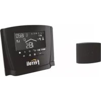
The radio thermostat clock is a 7 day radio frequency (RF) wireless thermostat/ timer which communicates with a special receiver designed to fit in the clock aperture of the boiler casing.
The radio thermostat clock is battery powered and can be sited wherever conventional room thermostats would normally be sited. See installation locations information on page 7.
The radio thermostat clock is a room thermostat and clock of highly advanced technology. The device is wireless and controls the heating via radio, providing both time control and comfortable room temperatures.

Assembly description
A Moveable sliding cover
B Keys for manual override function
C Window
D Keyboard
E Battery compartment
F Display

Technical data – RF Set, Transmitter
Power supply: 2 x 1.5 V AA LR6 alkaline batteries
Battery service life: 2 years (depending on switching frequency)
Room temperature display resolution: 0.1°C
Temperature setting display: Program: +5°C...+32°C (0.5°C steps)
Frost protection: 5°C (adjustable 3°C...7°C)
Time setting resolution: Time of day: 1 minute
Program: 30 minutes
Programming:
weekly program with up to 48 time and temperature programs changes
Pre-programmed programs:
4 + 1 user-defined
RF signal:
868.3 MHz
RF signal range:
Indoor 30 m (2 walls + 1 ceiling)
Protection class / type:
II / IP40
Operating temperature range:
Max. 45^ C
Operating humidity range:
10% to 90% RH non-condensing
Dimensions H x W x D (mm):
87×154×27

Technical data – RF Set, Receiver
Power supply: 230 V +/-10% 50-60 Hz
Switching output: SPDT (potential-free)
Switching capacity: 5 (1) A 250 V AC
RF signal: 868.3 MHz
RF signal range: Indoor 30 m (2 walls + 1 ceiling)
Protection class / type: II / IP20
Operating temperature range: Max. 45°C
Operating humidity range: 10% to 90% RH non-condensing
Dimensions H x W x D (mm): 60 x 60 x 32

Installation and assembly
General information
!

natural_image
Diagram showing a tree trunk with intersecting lines and three circular objects below, one emitting light rays (no text or symbols)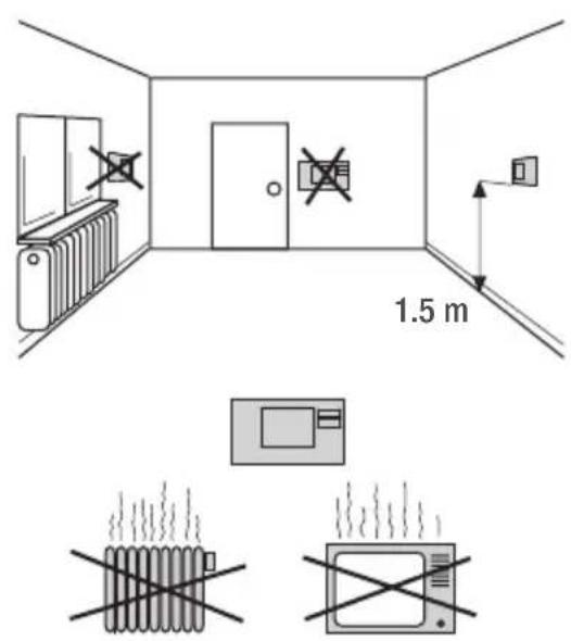

Modena C HE
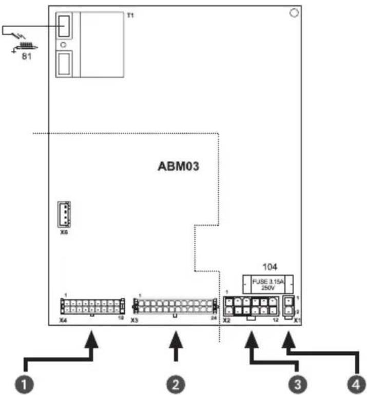

Wiring diagram

flowchart
graph TD
    A["Radio Thermostat Clock Receiver"] -->|N| B["230V AUX"]
    B -->|L| C["139"]
    C --> D["186"]
    D --> E["44"]
    E --> F["114"]
    F --> G["10"]
    G --> H["13"]
    H --> I["12"]
    I --> J["14"]
    J --> K["15"]
    K --> L["16"]
    L --> M["17"]
    M --> N["18"]
    N --> O["19"]
    O --> P["20"]
    P --> Q["21"]
    Q --> R["22"]
    R --> S["23"]
    S --> T["24"]
    T --> U["25"]
    U --> V["26"]
    V --> W["27"]
    W --> X["28"]
    X --> Y["29"]
    Y --> Z["30"]
    Z --> AA["31"]
    AA --> AB["32"]
    AB --> AC["33"]
    AC --> AD["34"]
    AD --> AE["35"]
    AE --> AF["36"]
    AF --> AG["37"]
    AG --> AH["38"]
    AH --> AI["39"]
    AI --> AJ["40"]
    AJ --> AK["41"]
    AK --> AL["42"]
    AL --> AM["43"]
    AM --> AN["44"]
    AN --> AO["45"]
    AO --> AP["46"]
    AP --> AQ["47"]
    AQ --> AR["48"]
    AR --> AS["49"]
    AS --> AT["50"]

    subgraph Control Signals
        direction TB
        White_White_White_White_White_White_White_White_White_White_White_White_White_White_White_White_White_White_White_White_White_White_White_White_White_White_White_White_White_White_White_White_White_White_White_White_White_White_White_White_White_White_White_White_White_White_White_White_White_White_White_Black
        White_White_White_White_White_White_White_White_White_White_White_White_White_White_White_White_White_White_White_White_White_White_White_White_White_White_White_White_White_White_White_White_White_White_White_White_White_L
        White_Spades connect to terminals 1 & 2 at the clock
        Radio,Thermostat_Clock_Receiver
        Remove_Link and_Connect Lead to terminals 3 & 4 at the receiver
    end

Installation of the receiver
Wiring Connections

natural_image
Pure electrical circuit lines without any symbols
1 - Live (Brown)
2 - Neutral (Blue)
3 - Switched circuit (White #1)
4 - Switched circuit (White #2)
5 - No connection required
Commissioning, please turn to page 11.

Installation of the radio link
The transmitter and receiver are pre-commissioned. If the radio link doesn't work correct, follow the sequence of commissioning.
Press and hold the black button of the receiver until the LED light has flashed twice. Release the button and the LED light will remain illuminated.
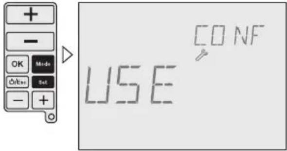
Press and hold MODE-button and SET-button of the transmitter at the same time for more than 3 seconds to enter into the User menu. Then press the OK-button until RF Comm is displayed.
1

2

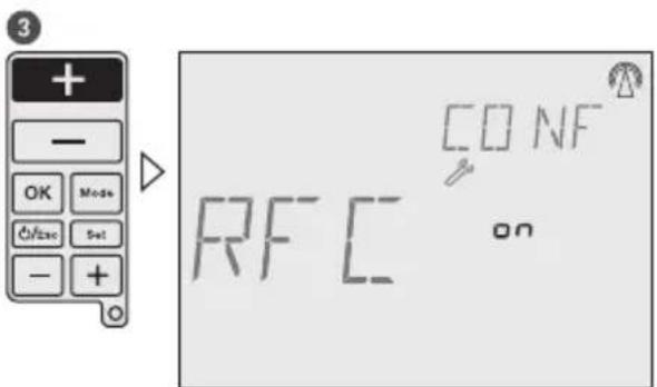
Press upper + button (- button disables the RF signal) to enable an continuous RF signal. The receiver LED will go out as soon as a signal from the transmitter is received. Then press the OK-button, the radio link between transmitter and receiver is now established. Press the ESC-button to return to Auto mode.
Receiver: When operating in heating mode and an ON signal is received, the LED illuminates continuously. When an OFF signal is received, the LED is off (and flashes periodically at longer intervals). Is no valid radio signal received from the transmitter for more than one hour (e.g. low battery) the emergency operating mode will be activated. The LED flashes every 0.5 seconds.

12

Open housing Wall mounting

natural_image
Technical line drawing of a mechanical device with a curved arrow indicating rotation or change (no text or symbols present)
natural_image
Technical line drawing of a mechanical assembly with no visible text or symbols
Close housing Insert batteries
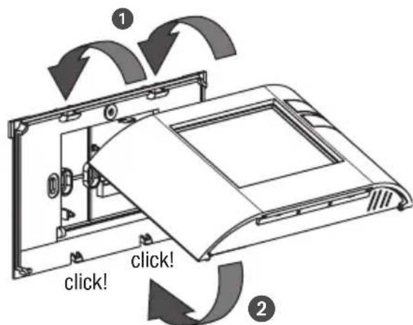

Only use 2 x 1.5 V type AA.

Operating and adjustment
Operating information
- Flashing texts signal the need for an entry. If no button is pressed for 2 minutes, the device reverts to the Automatic mode.
- All settings need to be confirmed with OK.
- All settings saved will remain in the memory.
- The histogram shows the programmed temperature profile
7 - 14°C = displayed as one segment
15 - 24°C = one segment displays 1°C
over 24^ C = one segment displays 2^ C
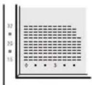

Display

A Current week day
B Battery
C RF signal
D Current time
E Set temperature
F Off mode
G Histogram over 24 hours
H Current temperature
I Operating mode
J Status indication
K Current date

Function keys

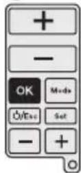
A +/- buttons used to increase/decrease temperatures.
B OK-button to confirm settings and go to the next step.
C MODE-button to select from the available operating modes.
D ESC-button used for ON/OFF, go one step back in menu or return to main menu by pressing the button more than 3 seconds.
E SET-button for settings following commissioning.
F +/- buttons used to increase/decrease hours, days and events.
G RESET-button to return to factory settings. The programs are retained in the case of a reset. The date and time must be set again. Press reset button with a blunt object (pen).

Configuration
General information
For the use of this manual you must observe the following informations:

A Sequence of operation
B Pressed buttons are shown in black.
C Flashing elements are shown in black
D Fixed elements are shown in grey
- Buttons which can be pressed during an action are shown in black. The related display is also shown in black.
- Follow exactly the numbers of the sequence of operation.
- The configuration of the device is described based on configuration.
- After starting the device for the first time, follow the menu for a correct configuration of the device.
- Following commissioning, you can also change the configuration by pressing the SET-button.

Initial start-up
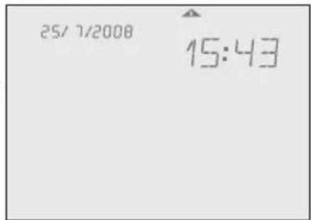
Set date and time
Sequence for setting the date and time during initial start-up.
15/6/2008 appears as factory default.
To set the date and time after initial start-up press the SET-button, then choose Date or Time Menu with the upper +/- buttons and confirm with OK.
1

2


3
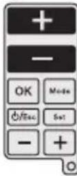
▶

5
The time is set in the same way as the date.
4


6
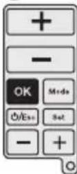
△

Programming
Sequence for specifying programs during initial start-up.
To specify programs after initial start-up press the SET-button, then choose the Prog menu with the upper +/- buttons and confirm with OK.


| Mo | Tu | We | Th | Fr | Sa | Su |
| 1 | 2 | 3 | 4 | 5 | 6 | 7 |
| 1 | 2 | 3 | 4 | 5 | 6 | 7 |
| 1 | 2 | 3 | 4 | 5 | 6 | 7 |
| 1 | 2 | 3 | 4 | 5 | 6 | 7 |

Choose between:
7 days – one programm
5-2 days – one program per day block
1-7 days – each day an individual program
free block formation – one program per day block

22

Select program
Each weekday or day block must be allocated a program P1, P2, P3, P4 (pre-defined) or Pd (user-defined).

line
| Time (hours) | Temperature (°C) | | ------------ | ---------------- | | 0 | 15 | | 3 | 15 | | 6 | 20 | | 9 | 20 | | 12 | 17 | | 15 | 17 | | 18 | 21 | | 21 | 21 | | 23 | 5 |
line
| Time (hours) | Temperature (°C) | | ------------ | ---------------- | | 0 | 15 | | 3 | 15 | | 6 | 15 | | 9 | 20 | | 12 | 20 | | 15 | 20 | | 18 | 20 | | 21 | 20 | | 23 | 20 |
line
P3 | Time (s) | Temperature (°C) | | :--- | :--- | | 0 | 15 | | 3 | 20 | | 6 | 20 | | 9 | 18 | | 12 | 20 | | 15 | 17 | | 18 | 21 | | 21 | 5 | The chart displays a single data series with values ranging from 15°C to 21°C. The x-axis is labeled with integers from 0 to 23, and the y-axis is unlabeled but represents temperature in degrees Celsius. The legend is not present as only one data series is plotted.
line
P4 | Time (h) | Temperature (°C) | |---|---| | 0 | 15 | | 3 | 15 | | 6 | 20 | | 9 | 20 | | 12 | 17 | | 15 | 17 | | 18 | 21 | | 21 | 21 | | 23 | 15 |Pd User-defined program.
During initial start-up, program will be shown with 15°C from 00:00 to 23:59 PM.

If you wish you can modify the pre-defined programs. Use the upper +/- buttons to increase/decrease the temperature of each segment by 0.5°C. Use the lower +/- buttons to go forward/backward 30 minutes each time and copy the selected temperature value.
5


6

▶


Settings
After commissioning you can change the date, time, temperature and time programming. By pressing the upper +/- buttons you jump to the different menus.
1-3 = adjustment of date
2-3 = adjustment of time
3-3 = adjustment of time and temperature programming
1

2


3
You are now able to adjust the date as described in the initial start-up. The sequence of setting the time is similar to the method for setting the date.
4

△
PROG
3-3
5
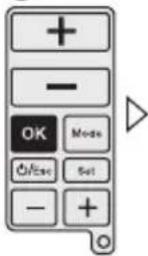
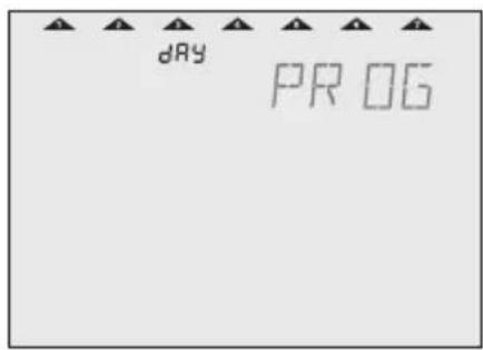
With the lower +/- buttons you can choose days or day blocks for programming and confirm with OK. Go to operation number 6.
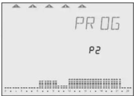
By pressing the OK-button you can choose between the pre-defined programs P1 – P4 or the user-defined program Pd. Go to operation number 7.

6

△

7

△
8


9

▶


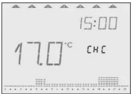
By pressing the lower +/- buttons you can go through the program to check it.
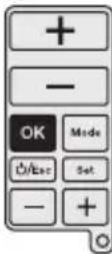
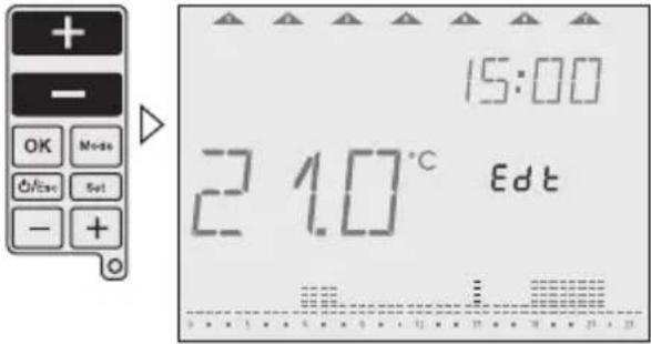
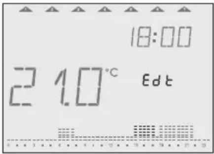
For editing the program, use the upper +/- buttons to increase/decrease temperature in each segment by 0.5°C. Use the lower +/- buttons to go forward/backward and copy the selected temperature value.
10
11
12


Operating modes
Set operating modes
Follow the sequence for selecting the desired operating mode. The operating modes in the device appear in the same order as described here.

Press and hold the ESC-button for 3 seconds to return to Auto mode.
Example:
1

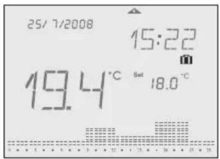
2


Auto
Symbol: Auto
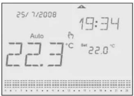
After each programming session, the device automatically returns to the Auto mode. The predefined or user-defined program run here.


Manual-ECO-Fix
Symbol: Auto
Manual-ECO-Fix mode calculates an average temperature of the actual program. This temperature is kept for the whole day until any user's intervention is made. To return to Auto mode, press OK.
The average temperature is the starting point for increasing or decreasing the desired temperature, pressing upper +/- buttons. The new temperature set value is then, after 3 sec., set for all day long.
Example: 4 different temperatures in the actual program (e.g. 17°C, 19°C, 20°C and 22°C). Average temperature is then 19,5°C.
3


4


Cleaning mode
Symbol:
This mode sets the device into OFF mode for a preset time of 2 hours. During the cleaning time, remaining time is shown until running mode elapsed. After the Cleaning mode is elapsed, the device returns into Auto mode.

To end Cleaning mode early, press ESC-button for more than 3 seconds.
The anti-freeze protection is granted.

32

Countdown mode
Symbol: ✗
This function runs into a desired set temperature during certain period of time. Adjustable period of time is 1 – 23 hours. After the time is elapsed, the device returns into OFF mode (Anti-freeze temperature is kept). During the Countdown mode, remaining countdown time is indicated.
Example: The device shall be run into OFF mode after 4 hours.

To end Countdown mode early, press ESC-button for more than 3 seconds.
3

4


Party mode
Symbol:
This mode allows the user to set a desired temperature during defined period of time. Adjustable period of time is 1 – 23 hours. After the time is elapsed, the device returns into the mode before the Party mode was activated. During the Party mode, the rest of the time is indicated.
Example: The temperature shall be set for 6 hours on 24°C.

To end Party mode early, press ESC-button for more than 3 seconds.
3
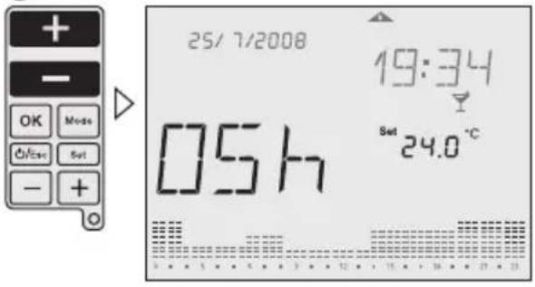
4


Holiday mode
Symbol:
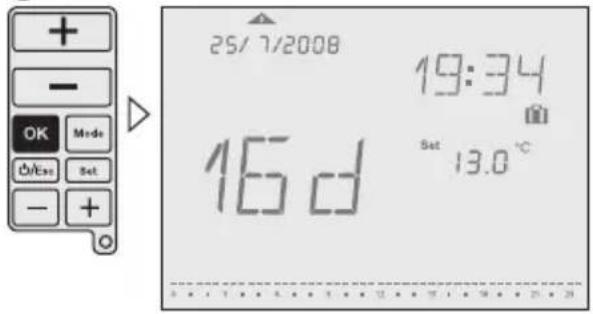
This function runs into a desired set temperature during certain period of time. Adjustable period of time is 1 – 90 days. After the time is elapsed, the device returns into the mode before the Holiday mode was activated. During the Holiday mode, the rest of the days is indicated.
Example: The temperature shall be set for 16 days on 13^ C.

To end Holiday mode early, press ESC-button for more than 3 seconds.
3

4

Operating status
Manual override
Symbol:
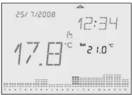
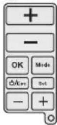
While the sliding cover is closed, you can temporarily adjust the temperature in the current period with the upper +/- buttons. It is not necessary to confirm the setting with OK. The setting will remain as temperature set value until the next programmed change (time and temperature) appears.
To return into Auto mode, press and hold upper +/- buttons for 3 seconds, or open the sliding cover and press OK-button.
1

2


OFF mode
Symbol: OFF
This mode switch off the device completely. To activate this mode press and hold ON/OFF/ESC-button for more than 5 seconds. To leave this mode press and hold the ON/OFF/ESC-button again for more than 5 seconds.

The anti-freeze protection is granted.


Low battery
Symbol:
A low battery level is indicated with the battery icon in the display. Please change the batteries. If batteries are not placed or are installed in the wrong polarity,

If the battery goes completely empty, the programming is protected.


User menu/Configuration
Symbol: ↗
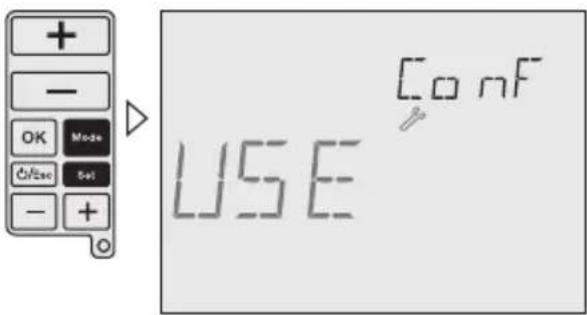
Press the MODE-button and SET-button at the same time until User menu is shown in the display. To go to previous menu press ESC-button. It is possible to adjust:
• RF commissioning (RFC): Enable/disable continuous radio signal
- Offset (OFS): Possibility to adjust/modify the measured temperature (-5°C...+5°C)
- Summer/Winter time (SWT): enable/disable automatic summer/winter time change
• Time Format (TMF): possibility to change time format into 24 hours or 12 hours (default: 24 hours)
- Restore Default (DFL): Restore values to factory default status.
Use lower +/- buttons to navigate through menus.
Use upper +/- buttons to change values and OK to confirm.

Installation menu
Symbol: ↗
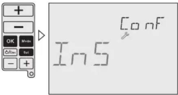
To access this Configuration menu, press the MODE-button, the OK-button and SET-button at the same time until Installer menu is shown in the display. Press ESC-button to go to previous Menu.

The adjustments in this menu are only for experts.
All possibilities for adjustment are shown with a self-explaining, floating real text in the display.
Use lower +/- buttons to navigate through menus.
Use upper +/- buttons to change values and OK to confirm.
40

Following adjustments are possible:
High Temp (HIT): set maximum temperature value for programming from low temperature value up to +32°C (default: +32°C)
Low Temp (LOT): set minimum temperature value for programming from +7°C up to high temperature value (default: +7°C)
Frost protection (FRT): set anti freeze minimum temperature value from +3°C to +7°C (default: 5°C)
Regulation (REG): possibility to select between PID or 2 points regulation (default: 2 points)
Differential (DIF): possibility to modify differential value from 0,1 K to 0,9 K (default: 0,2 K)
Keypad Lock (LOK): enable keypad to protect against non authorized interventions To enable/disable the keypad lock press and hold MODE- and ESC-button for more than 3 seconds.
Operating hours (OPT): this feature shows total operating running time (max. 99.999 hours)
Battery Level (BAT): battery charge level is shown on display
For your notes:
For your notes:
Ferroli
Because of our constant endeavour for improvement details may vary from those quoted in these instructions
Should you require any assistance during the installation call our Technical Service Helpline on 0843 479 0 479
Ferroli Limited,
Lichfield Road, Branston Industrial Estate, Burton Upon Trent, Staffordshire, DE14 3HD
Service/Technical Tel: 0843 479 0 479

- Table of contents
- Safety instructions
- Product details
- Assembly description
- Technical data – RF Set, Transmitter
- Technical data – RF Set, Receiver
- Installation and assembly
- General information
- Installation of the receiver
- Installation of the radio link
- Operating and adjustment
- Operating information
- Configuration
- Initial start-up
- Set date and time
- Programming
- Select program
- Settings
- 3
- 4
- 5
- Operating modes
- Set operating modes
- Auto
- Manual-ECO-Fix
- Cleaning mode
- Countdown mode
- Party mode
- Holiday mode
- Operating status
- Manual override
- OFF mode
- Low battery
- User menu/Configuration
- Installation menu
- Ferroli
- Ferroli Limited,
Brand : FERROLI
Model : ZU0800009
Category : Thermostat