
Theta+ - Thermostat FERROLI - Free user manual and instructions
Find the device manual for free Theta+ FERROLI in PDF.


| Type | Heating control unit (standard unit, boiler control panel, room control unit) |
| Power Supply | 230 V~, 50 Hz, 6/-10% |
| Number of Heating Circuits | Up to 2 mixed circuits + 1 direct circuit |
| Data Bus | Bi-directional, shielded cable, max 100 m, addressable (10, 20, 30, 40, 50) |
| Sensor Types | Outdoor (AF 200), immersion (KVT 20), flow (VF 202/204), flue gas/solar (PT1000) |
| Operating Temperature Range (sensors) | -20 °C to 250 °C (depending on sensor) |
| User Interface | Rotary knob and buttons; LCD display with segments |
| Mounting | Standard unit: flush into boiler panel; Room unit: wall-mounted (1.2-1.5 m height) |
| Protection Class | IP? (not specified, assume IP20 for indoor use) |
| Safety Features | Safety temperature limiter (STL), alarm messages, frost protection |
| DHW Functions | Domestic hot water charging pump, legionella protection, circulation pump control |
| Solar Integration | Solar panel pump, buffer tank, energy balance calculation |
| Cascade Control | Up to 5 control units (addresses 10-50), sequential or parallel operation |
| Alarm Log | Stores up to 20 alarm messages with date and time |
| Language Selection | Multiple languages (DE, GB, FR, IT, NL, ES, PT, HU, CZ, PL, RO, RU, TR, S, N, BG) |
| Maximum Cable Length (sensors) | 100 m for low voltage cables (0.5 mm²) |
| Maximum Cable Length (data bus) | 100 m, shielded J-Y(St)Y 1x2x0.6 mm² |
| Variable Inputs/Outputs | 3 variable inputs, 2 variable outputs (programmable) |
| Standards Compliance | EMC-conform installation, VDE 0100, EN 60555-2 |
| Accessories | Wall socket MS-K, outdoor sensor AF, immersion sensor KVT, flow sensor VF |
Frequently Asked Questions - Theta+ FERROLI
User questions about Theta+ FERROLI
0 question about this device. Answer the ones you know or ask your own.
Ask a new question about this device
Download the instructions for your Thermostat in PDF format for free! Find your manual Theta+ - FERROLI and take your electronic device back in hand. On this page are published all the documents necessary for the use of your device. Theta+ by FERROLI.
USER MANUAL Theta+ FERROLI
For the heating specialist Operating and installation instructions
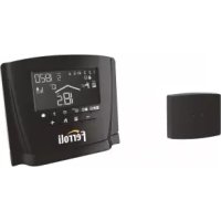
Standard unit
Remote unit RS
Boiler control panel

Contents
General safety instructions .... 3
Safety measures for EMC - conform installation....3
Standard unit....5
Mounting 5
Electrical installation 5
Terminal assignment 6
Boiler control panel....7
Mounting 7
Electrical installation 7
Terminal assignment 8
Wall socket MS-K 9
Electrical installation....9
Terminal assignment 10
Room control unit RS 11
Mounting location....11
Mounting 11
Terminal assignment 12
Electrical connections (control unit)....12
Data bus addressing....12
Equipment....14
Outdoor sensor AF (OT)....14
Immersion sensor KVT 14
Flow sensor VF 15
Resistance values of the sensor elements versus temperature.... 16
Starting up the control unit....17
Code-Input 17
Automatic SET-Function 18
Alarm messages....20
Heating system information 21
Level synoptic 25
Synoptic of the specialist parameters and control options 28
General safety instructions
All electrical connections and safety measures have to be carried out by a specialist according to the valid norms and VDE-guidelines as well as the local instructions.
The electrical connection must be fix (see instructions by VDE 0100).
The electrical connection has to be done according to the wiring diagram of the respective boiler control panel.
Important!
Deenergize the boiler before opening. Unprofessional plugging attempts under voltage may damage the control or cause dangerous electrical shocks.
Safety measures for EMC - conform installation
- Cables with mains voltage must be generally installed separately from sensor and data bus cables. In this case a minimum distance of 2 cm must be observed. Crossing of lines is permitted.

Fig. 1: Minimum distance for cable installations
-
Controls with own mains connection require a separate installation of mains and sensor or data bus cable. When using cable ducts such with internal separators are recommended.
-
Installing control or remote units close to other components with electro magnetic emission such as solid state relays, motors, transformers, dimmers, micro wave ovens, TV-sets, loud-speakers, computers, radio telephones etc. a minimum distance of 40 cm must be observed.
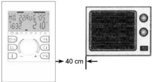
Fig. 2: Minimum distance to other electric supply
-
Between remote units and standard unit a minimum distance of 40 cm has to be observed. Several standard units may be installed side by side.
-
The mains connection of the heating plant (standard unit or boiler control panel) must be carried out as an independent electric circuit. It is not permitted to install fluorescent tubes or other machines that could produce interferences to the same electrical circuit.

Fig. 3: Leading of electrical cables in the boiler room
- All data bus cables must be carried out in shielded version.
Recommended cable: J-Y(St)Y 1 x 2 x 0,6 mm ^2
- The shielding of the cable has to be connected with earth potential, i.e. boiler covering, connecting terminals for earth potential etc. Multiple grounding is not permitted (humming loop).
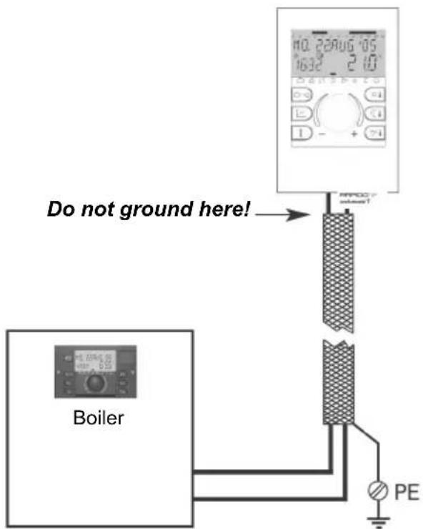
Fig. 4: Single grounding of shielding
In stellate data bus networks shall be no double grounding. The grounding must be made unilaterally in the star-point.
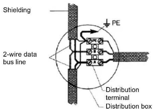
Fig. 5: Grounding in star shaped networks
- The outside sensor may not be installed close to transmitter- or receiver-equipment (on garage walls close to receivers for radio-controlled garage door openers, ham operator antennas, radio controlled alert systems or close to big radio transmission plants).
Cable dimensions and maximum cable length
For all 230V\~ cables such as power supply, burner, pumps, actuators: 1.5 mm ^4 Maximum cable length:
Unlimited cable length within house installation
For all low voltage cables such as sensors, extern selectors, bus and analogue in- and outputs, heat requiring by means of extern contact, modem connection cables, etc.: 0.5 mm ^2
Maximum cable length: 100 m Longer distances are possible but increase the risk of interferences.
Data bus connections: 0.6 ~mm^2
Recommended cable:
J-Y(St)Y 1 x 2 x 0.6 mm²
Maximum cable length: 100 m
Longer distances are possible but increase the risk of interferences.
Standard unit
Mounting
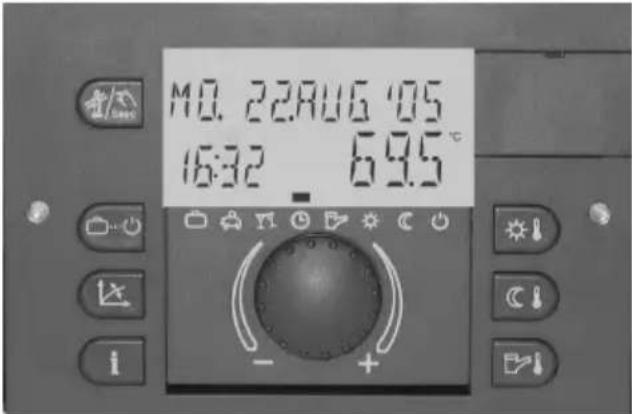
All standard units are designed exclusively as units for incorporation and will be installed from the front side into the boiler panel after finishing the electrical wiring.
The instrument is fastened by a quarter turn clockwise of the quick clamping devices at the left and right side of the front panel (1).
Removal is done in opposite direction.

Electrical installation
The electrical installation to the control equipment is done at the back side of the instrument via the four enclosed connecting terminals X1, X2, X3 and X4 corresponding to the identification on the coloured-marked connection pads.

All blue marked connecting terminals (X1) work with safety low voltage and must not get into contact with the mains voltage. At non-observance the instrument will definitely be destroyed and any warranty gets lost.
Red marked connecting terminals (X2...X4) principally may work with mains voltage according to the current operation conditions.
For further information see documentation of the boiler manufacturer.
Electrical connection see next page.
Note:
Cables with mains voltage must be installed separate from low voltage cables (data bus, sensors etc.). It is strictly prohibited to use one cable for both voltages. Sensor cables and data bus cables may not be installed together with mains voltage cables supplying electrical appliance which are not suppressed according to EN 60555-2.
Terminal assignment
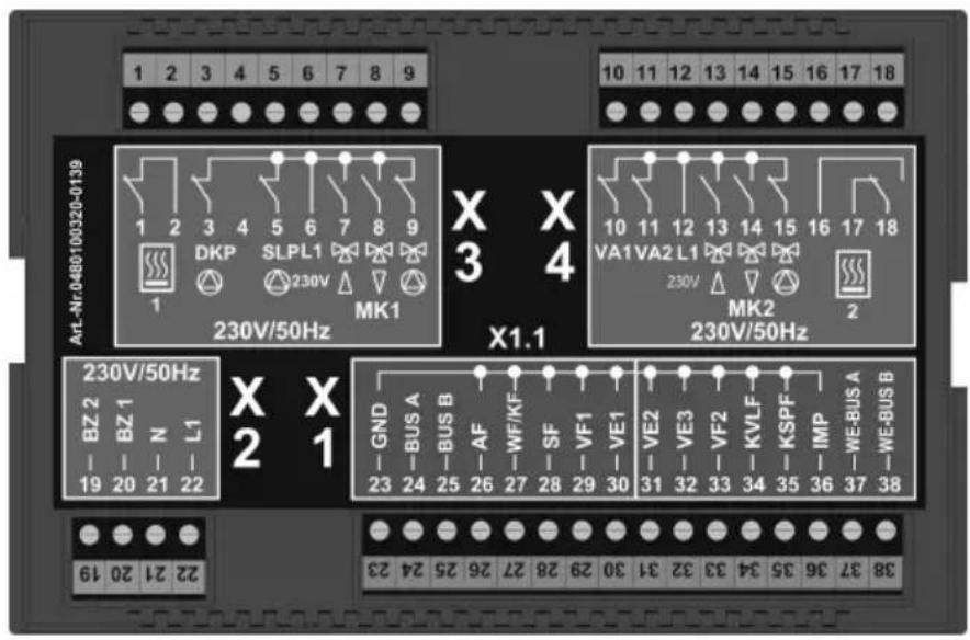
230 V\~ Connections
1 – Floating exit for heat generator, output (stage 1)
2 - Floating exit for heat generator, input (stage 1)
3 – Pump for direct heating circuit
4 – not connected, used for coding
5 – Domestic hot water charging pump
6 - L 1 / 230 V\~
7 - Mixing valve 1 OPEN
8 - Mixing valve 1 CLOSED
9 – Pump for mixed heating circuit 1
10 – Variable output 1
11 – Variable output 2
12-L 1/230 V\~
13 - Mixing valve 2 OPEN
14 - Mixing valve 2 CLOSED
15 – Pump for mixed heating circuit 2
16 -
17 - Floating exit for heat generator, output (stage 2)
18 - Floating exit for heat generator, input (stage 2)
19 – Operat. hours counter burner - (stage 2)
20 – Operat. hours counter burner - (stage 1)
21 - N / 230 V\~
22 - L 1 / 230 V\~} mains
Sensor and data bus connections
23 – Ground for data bus and sensors
24 – Data bus signal A
25 – Data bus signal B
26 – Outdoor sensor
27 - Sensor heat generator/boiler
28 – Domestic hot water sensor
29 - Flow sensor for mixed heating circuit 1
30 - Variable input 1
31 - Variable input 2
32 – Variable input 3
33 - Flow sensor for mixed heating circuit 2
34 – Solar panel flow sensor ^1)
35 – Solar tank sensor
36 - Pulse input
37 - Heat generator-data bus A
38 - Heat generator-data bus A
Mounting into boilers
See technical documentation of boiler manufacturer.
Wall mounting
See technical documentation »wall mounting set THETA WG«
1) Solar application only
Boiler control panel

Mounting
The boiler control panel is completely prewired and will be mounted from the front side into the panel cut-out of the boiler after finishing the electrical wiring. The panel is fastened with the four enclosed screws.
Removal is done in opposite direction.
The sensor of the safety temperature limiter as well as the boiler sensor will be inserted into the sensor immersion pocket of the boiler.
Important: Do not crease or damage the capillary tubing of the safety temperature limiter.
For further information see documentation of the boiler manufacturer.
Accessories on demand
For easier installation optional swing-out aids can be ordered. These aids will be snapped into both left and right sides of the panel and prevent that the panel falls down when opening.
Electrical installation
The electrical installation is done at the back side of the boiler control panel via the plugged-in connection terminals corresponding to the identification on the coloured-marked connection pads.
Low voltage connecting terminals:

All blue marked connecting terminals work with safety low voltage and must not get into contact with the mains voltage.
At non-observance the instrument will definitely be destroyed and any warranty gets lost.
Electrical connection see next page.
Mains voltage connecting terminals:
Red marked connecting terminals principally may work with mains voltage according to the current operation conditions.
Electrical connection see next page.
Note:
Cables with mains voltage must be installed separate from low voltage cables (data bus, sensors etc.). It is strictly prohibited to use one cable for both voltages. Sensor cables and data bus cables may not be installed together with mains voltage cables supplying electrical appliance which are not suppressed according to EN 60555-2.
Terminal assignment

230 V\~ Connections
1 - Mains 230V\~ +6/-10%, 50 Hz
2 – Safety circuit 1
3 – Safety circuit 2
4 – Burner 1 (single step boilers)
5 – Burner 2 (double step boilers)
6 – Pump for direct heating circuit
7 – Domestic hot water charging pump
8 – Pump for mixed heating circuit 1
9 – Actuator mixing valve 1
10 – Pump for mixed heating circuit 2
11 – Actuator mixing valve 2
12 – Variable output 1
depending of programmation
(see level HYDRAULIC)
13 – Variable output 2
depending of programmation
(see level HYDRAULIC)
Sensor and data bus connections
14 – Outdoor sensor
15 – Sensor heat generator/boiler
16 – Domestic hot water sensor
17 - Flow sensor for mixed heating circuit 1
18 - Flow sensor for mixed heating circuit 2
19 – Variable input 1
20 - Variable input 2
21 – Variable input 3
22 - Solar panel flow sensor ^1)
23 – Solar tank sensor ^1)
24 - Pulse input
25 – Data bus T2B
26 – Data bus RS 485 ^2)
^1) Solar application only ^2) high efficiency condensing boilers only
Wall socket MS-K
natural_image
Close-up of a vintage air conditioner control panel with buttons and display (no readable text or symbols)Application:
The wall socket MS-K is used for wall mounting application of all types of standard units.
Type
The wall-mounted connection base is intended for the sole purpose of housing the standard unit.
After plugging the standard unit into the wall socket and after finishing the electrical wiring ready for start up.
Electrical installation
1- Break out the impressed cable inlets due to the required number and seize on top side or lower side of the wall socket according to the position of the cable channel.
Note:
Cable strain relief is prescribed if no cable duct is used.
2- Turn locking screws (1) horizontally and pull off terminal cover to the side.
3- Fix wall socket on a flat background using enclosed screws and plugs. Use drill pattern the enclosed
4- Electrical installation has to be carried out according to plant and connectivity as shown on next page.

The connecting terminals of terminal blocks X5 and X6 at the left side work with safety low voltage and must not get into contact with the mains voltage. At non-observance the instrument will
definitely be destroyed and any warranty gets lost.
The connecting terminals of terminal blocks X7 to X10 principally may work with mains voltage according to the current operation conditions.
The wall socket is equipped completely with screwless terminals. Press lever before inserting stripped wire into terminal.
5- Attach and clamp the side terminal-covers.
6- Insert standard unit with evenly distributed pressure. The electrical connection is done by plugging the instrument into the terminals at the socket print. Lock standard unit with both quick clamping devices left and right.
Note:
Cables with mains voltage must be installed separate from low voltage cables (data bus, sensors etc.). It is strictly prohibited to use one cable for both voltages. Use cable ducts equipped with separators, if necessary.
Terminal assignment
230 V\~ Connections

flowchart
graph LR
    subgraph X7
        A["1"] -->|T1| B["L1(mains)"]
        C["2"] --> B
        D["3"] --> B
        E["4"] --> B
        F["5"] --> B
        G["6"] --> B
        H["7"] --> I["B4"]
        J["8"] --> K["B5"]
        L["9"] --> M["T6"]
        N["10"] --> O["T8"]
        P["11"] --> Q["T7"]
    end
    subgraph X9
        R["1"] --> S["HC"]
        T["2"] --> S
        U["3"] --> V["DHW"]
        W["4"] --> V
        X["5"] --> Y["M"]
        Z["6"] --> AA["MC1"]
        AB["7"] --> AC["LVO1"]
        AD["8"] --> AE["LVO2"]
        AF["9"] --> AG["M"]
        AH["10"] --> AI["MC2"]
        AJ["11"] --> AK["N (mains)"]
    end
    style X7 fill:#f9f,stroke:#333
    style X8 fill:#ccf,stroke:#333
    style X9 fill:#cfc,stroke:#333
Sensor and data bus connections Burner connections
X5 X6
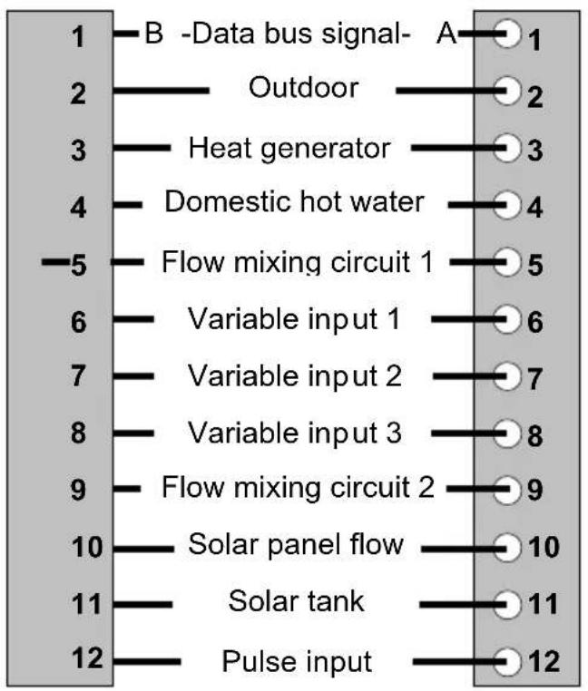
flowchart
graph TD
    A["1 -Data bus signal-"] --> B["Outdoor"]
    B --> C["Heat generator"]
    C --> D["Domestic hot water"]
    D --> E["Flow mixing circuit 1"]
    E --> F["Variable input 1"]
    F --> G["Variable input 2"]
    G --> H["Variable input 3"]
    H --> I["Flow mixing circuit 2"]
    I --> J["Solar panel flow"]
    J --> K["Solar tank"]
    K --> L["Pulse input"]
    style A fill:#f9f,stroke:#333
    style L fill:#f9f,stroke:#333
T1 Control terminal stage 1
T2 Control terminal stage 1
B4 Op. hours counter burner stage 1
B5 Op. hours counter burner stage 2
T6 Control terminal stage 2
T7 Control terminal stage 2
T8 Control terminal stage 2
L1 Mains 230 V\~ (live)
N Mains 230 V\~ (neutre)
Pumps and actuators
HC Pump for direct heating circuit
DHW Domestic hot water charging pump
MC1 Pump for mixed heating circuit 1
MC2 Pump for mixed heating circuit 2
1 m ▲ actuator mix. valve 1 (OPEN)
1 m ▼ actuator mix. valve 1 (CLOSE)
2 m ▲ actuator mix. valve 2 (OPEN)
2 m ▼ actuator mix. valve 2 (CLOSE)
L_v01^III Variable output 1 (live)
L_VO2 Variable output 2 (live)
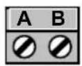
Boiler – Data bus
Room control unit RS
Mounting location
a – for applications without room sensor If the internal room sensor is not to be activated the RS may be mounted at any location indoors.
b – for applications with room sensor The remote unit should be fixed at a height of approx.1.20 – 1.50 m at a place most representative of all rooms. It is recommended to chose an interior wall of the coolest day room (such as entrance halls). In order to ensure sufficient air circulation at the room station, it must be mounted to the wall with a gap inbetween.
The remote unit must not be mounted
- at locations exposed to direct sunlight (seasonal variations should be taken into account)
- close to heat-producing appliances (televisions, refrigerators, wall lamps, radiators etc.)
- onto walls heated by under plaster heating pipes or chimneys.
-
onto outside walls
-
in corners behind curtains or shelves (due to insufficient ventilation)
– close to doors of unheated rooms (due to the influence of low temperature) - on unsealed under-plaster wiring boxes (influence of external low temperatures due to the chimney effect of installation tubes)
- in rooms with radiators controlled by thermostatic valves (mutual influence).
Mounting
After removing the front panel by pressing the locating lug at the lower side the socket can be mounted at the desired location using the enclosed dowel pins and screws. The cable for the bus connection has to be led through the lower cut-out of the socket.
Recommended connecting cable:
$$ J - Y (S T) Y 1 \times 2 \times 0. 6 m m ^ {2} $$
Maximum length: 100 m
Note:
For new installations use a under-plaster wiring box for perfect wiring.

natural_image
Exterior view of a white electronic device casing with visible internal components and mounting brackets (no text or symbols)Locating lug
Terminal assignment
The wiring between remote unit and standard unit or boiler control panel has to be made by a shielded data bus cable at terminals A and B of both units. The connecting terminals may not be changed and have to be installed according to the labelling of the terminals A/B in the wall socket. Changing the terminals causes no displaying.

natural_image
Technical line drawing of a mechanical or electrical component with labeled parts A and B, showing internal structure and mounting holes (no text or symbols beyond labels)Socket (unit removed)
After completing the electrical wiring hang remote unit conclusively on top side according figure on page 11 and turn down until it clicks into the wall socket.
Electrical connections (control unit)
See installation instructions of control unit.
Data bus addressing
In order to guarantee a selective communication between remote units and control units it is necessary to set every remote unit in the bi-directional data bus system to the corresponding data bus address.
This concerns in the same way the coupling of control units for extension of heating circuits, which communicate on the same data bus line.
By this reason control units and remote units are equipped with data bus addresses.
Data bus address (control unit)
Single control units must always have the address 10. In heating plants with several control units (maximum 5) the main controller that works on the burner gets the data bus address 10, the remaining controllers have to be set to addresses 20, 30, 40 and 50 one after the next.
Adjustment of data bus address of the control unit
To adjust the data bus address in the control unit the corresponding specialist code must be entered in the data bus level first (see starting up the control unit).
Adjustment of data bus address of the remote unit
The assignment between the data bus addresses of the control units and remote units is to a fixed factory preset scheme in accordance with the following table:
| Control unit Remote unit | |||
| Function | Data bus address | Heating circuit | Data bus address |
| Basic control unit | 10 | Direct circ.(HC)MC 1MC 2 | 111213 |
| 1. add-on unit | 20 | Direct circ.(HC)MC 1MC 2 | 212223 |
| 2. add-on unit | 30 | Direct circ.(HC)MC 1MC 2 | 313233 |
| 3. add-on unit | 40 | Direct circ.(HC)MC 1MC 2 | 414243 |
| 4. add-on unit | 50 | Direct circ.(HC)MC 1MC 2 | 515253 |
Adjustment of data bus address in the remote unit
A- First start-up
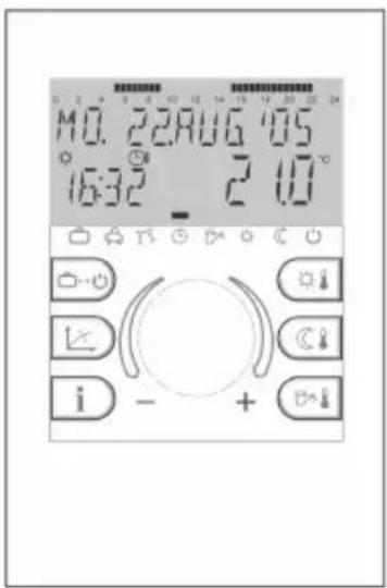
After completing the electrical installation and starting up the plant the complete segment character appears in the display of the remote unit.

Segment character
Following this, the desired language can be selected in accordance with the country code (DE, GB, FR, IT, NL, ES, PT, HU, CZ, PL, RO, RU, TR, S, N, BG) and activated.

Language
Onto that the device identification and data bus address is displayed:

Device identification
Type of control Software date Software-Version
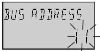
Address adjustment (See table to the left)
After setting the data bus address by means of the rotary knob and confirming by pressing the same once the number of the corresponding control unit appears automatically:

Data bus address
Direct heating circuit Basic control unit (1)
Important:
Double reservation of data bus addresses are not permissible and do lead automatically to troubles in the data transfer and to faulty control characteristic of the heating system.
B – Changing data bus addresses
A data bus address can be changed subsequently as follows:
1 - Disconnect remote unit from data bus line (by loosening plug-in connector at the lower end)
2 - Plug-in connector again while pressing the rotary knob until the address adjustment appears in the display.
3 - Adjust new data bus address by means of the rotary knob and confirm by pressing the same once.
Equipment Outdoor sensor AF (OT)
natural_image
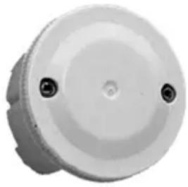
Circular mechanical component with two mounting holes (no text or symbols visible)Outdoor sensor AF 200
Mounting location
The outdoor sensor should be installed on the most exposed and coldest side of the building (north or north-west) so that it does not collect any direct sun light particularly in the morning.
Note: Chose the corresponding side of building due to the direction of the preferential living area.
Never mount sensor onto external heat sources such as chimneys, hot air from air shafts, sunlight or black undergrounds etc. since this will falsify the measured values considerably. The cable outlet must be directed downwards in order to avoid the intrusion of moisture.
Electrical installation
1- Install sensor cable to the sensor location
2- Loosen lid screws and remove top
3- Mount open sensor case with enclosed central fixing screw. Use sealing ring! Cable outlet must be directed downwards!
4- Insert sensor cable. The cable insulation must be encircled by the sealing lips of cable entry.
5- Set up electrical connection. For the electrical installation preferably a 2-core cable with at least sectional view of 1mm^2 is recommended.
The connection is made at the screw terminal block inside the sensor case and may be changed.
6- Put on lid again and screw it firmly with the case. Pay attention to correct seat of sealing ring.
Immersion sensor KVT

natural_image
Coiled black cable or wire against white background (no text or symbols)Options:
KVT 20/2/6 2 m cable length
Application: Boiler sensor, hot water sensor (for boiler integrated hot water tanks), return flow sensor
KVT 20/5/6 5 m cable length
Application: Hot water sensor (for add-on tanks, buffer tanks, solar collector return flow sensor etc.
Mounting location:
In the immersion sleeve of the respective application.
Mounting into boilers or other heat sources
Bend clutch spring to sensor top and insert sensor together with the capillary sensors of boiler thermostat (KTR), safety temperature limiter (SLT) and boiler thermometer (KTA) into the immersion sleeve. Use spring clip if necessary.
Mounting into hot water or buffer tanks
Bend clutch spring to sensor top and insert sensor according to the instructions of the manufacturer into the dry immersion sleeve of the respective hot water tank.
Terminal assignment
Connect sensors at the corresponding terminals of the respective control unit (see terminal diagram). The terminals may be changed.
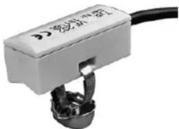
Flow sensor VF
natural_image
Close-up of a mechanical component with a black cable and metallic connector (no visible text or symbols)Feeding sensor VF...
Options:
VF 202 2 m cable length
Application: Contact sensor for mixer controlled heating circuits onto flow- or return pipes
VF 204 4 m cable length
Application: see VF 202
Mounting location:
Behind the mixer circuit pump, in the flow, ata minimum distance of 50 cm.
In case of use as return flow sensors:
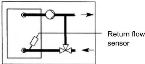
Controlled flow temperature addition by means of mixing valve

Bypass circuit by means of a bypass pump Boiler bypass pump
Mounting
Clean flow or return pipe thoroughly and apply heat conducting paste.
Attach sensor on the contact place in a flush way to the tube surface by means of the enclosed clamping band.
Pay attention to firm seat!
Terminal assignment
Connect sensors at the corresponding terminals of the respective control unit (see terminal diagram). The terminals may be changed.
Flue gas sensor / solar panel flow sensor

natural_image
Coiled black cable with two wires extending outward (no text or symbols visible)Immersion sensor PT 1000/6
Options:
PT1000/6 2.5 m cable length
Application: Flue gas temperature Collector flow temperature
Mounting location:
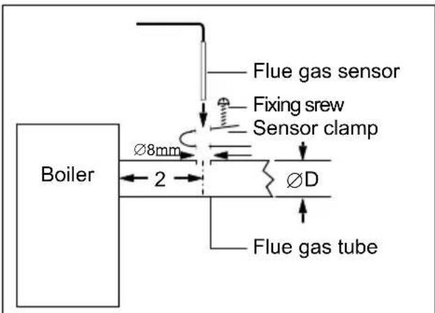
- In the flue gas tube in the minimum distance of the double tube diameter
- In the immersion sleeve of the solar collector.
Mounting in the flue gas tube
Mount sensor clamp according to illustration below. Determine immersion depth into the core flow of the flue gas and fix sensor.
Terminal assignment
Connect sensors at the corresponding terminals of the respective control unit (see terminal diagram). The terminals may be changed.
Resistance values of the sensor elements versus temperature
Heat generator/boiler sensor KVT 20
Outdoor sensor AF 200 DHW tank sensor/buffer sensor KVT 20
Feeding sensor VF 202/204
Boiler sensor (solid fuel) KVT 20
| T (°C) | R (kΩ) |
| - 20 | 1,383 |
| - 18 | 1,408 |
| - 16 | 1,434 |
| - 14 | 1,459 |
| - 12 | 1,485 |
| - 10 | 1,511 |
| - 8 | 1,537 |
| - 6 | 1,563 |
| - 4 | 1,590 |
| - 2 | 1,617 |
| ± 0 | 1,644 |
| 2 | 1,671 |
| 4 | 1,699 |
| 6 | 1,727 |
| 8 | 1,755 |
| 10 | 1,783 |
| 12 | 1,812 |
| 14 | 1,840 |
| 16 | 1,869 |
| 18 | 1,898 |
| 20 | 1,928 |
| 25 | 2,002 |
| 30 | 2,078 |
| T | R (kΩ) |
| 10 | 1,783 |
| 12 | 1,812 |
| 14 | 1,840 |
| 16 | 1,869 |
| 18 | 1,898 |
| 20 | 1,928 |
| 25 | 2,002 |
| 30 | 2,078 |
| 35 | 2,155 |
| 40 | 2,234 |
| 45 | 2,314 |
| 50 | 2,395 |
| 55 | 2,478 |
| 60 | 2,563 |
| 65 | 2,648 |
| 70 | 2,735 |
| 75 | 2,824 |
| 80 | 2,914 |
| 85 | 3,005 |
| 90 | 3,098 |
| 95 | 3,192 |
| 100 | 3,287 |
(°C)
Flue gas sensor, solar panel sensor PT1000
| T (°C) | R (kΩ) | T | R (kΩ)(°C) |
| 40 | 1,155 | 150 | 1,573 |
| 50 | 1,194 | 160 | 1,611 |
| 60 | 1,232 | 170 | 1,648 |
| 70 | 1,271 | 180 | 1,685 |
| 80 | 1,309 | 190 | 1,722 |
| 90 | 1,347 | 200 | 1,758 |
| 100 | 1,385 | 210 | 1,795 |
| 110 | 1,423 | 220 | 1,832 |
| 120 | 1,461 | 230 | 1,868 |
| 130 | 1,498 | 240 | 1,905 |
| 140 | 1,536 | 250 | 1,941 |
Starting up the control unit
Display test and device identification
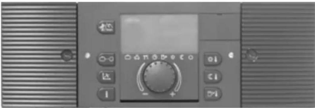
During the first switch-on of the control unit or at return of voltage after power failure all available display segments will temporary appear:
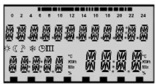
Segment character
The desired language can be selected.
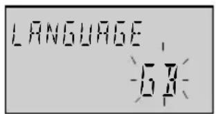
Language
Onto that device identification follows:

Provided that there is not any error message, the basic display with date, time and current boiler temperature will appear in the display.
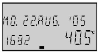
Basic Display
An active summer switch-off is represented by a sunshade symbol ( ).

Summer switch-off active
With acting frost protection function an ice crystal symbol appears in the display (※).

Frost protection active
Code-Input
Specialist code
After entering the specialist code the parameters which are certain for the heating specialist are released and can be processed according to the heating plant design.
To enter the specialist code the buttons and have to be pressed simultaneously for approx. 3 seconds until the request to enter the code will be displayed.

Every flashing digit can be modified with the rotary knob according to the code number and confirmed by pressing the knob once. The further digits are treated in same way.
After entering all digits correctly and confirming the last digit the specialist code is accepted by displaying INSTALLER OK, with wrong entry the message CODE ERROR will appear.
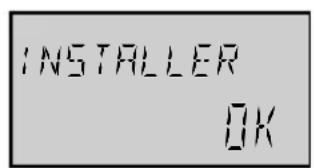

The factory preset code for the specialist is 1234
Note: Contact boiler manufacturer if the factory preset specialist code is not accepted!
Important: Released parameters are locked again if for the duration of no further service occurs. In this case the specialist code must be entered again.
Automatic SET-Function
This function allows to remove heating or hot water circuits from operation.
The control circuits are registered automatically, if their corresponding sensors are connected and provide acceptable measuring values. Control circuits without the corresponding sensors remain automatically without consideration.
The automatic set function will be activated after every switch-on.
Automatical activation
Provided that the auto-set function is turned on (see SYSTEM-Level - parameter 14) and the initial start-up date was not yet stored, connected or disconnected sensors will be registered automatically at every switch-on of the control unit. During this time error messages of sensors (short circuit or interruption) will be suppressed.
After the initial start-up date was stored, a modified sensor configuration can only be taken over by manual activation.
Manual activation
AUTO-SET function can be manually activated at any time by keeping the rotary knob pressed during the segment test when switching control unit on.
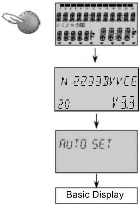
flowchart
graph TD
    A["Basic Display"] --> B["Device 2233B/VICE 20 V 3.3"]
    B --> C["Auto Set"]
    C --> D["Display"]
The auto set function registers the following sensors:
- Outdoor sensor
- Flow sensor 1
- Flow sensor 2
- Hot water tank sensor
– Heat generator /boiler sensor
Furthermore the auto set function is carried out only, if the control circuits which are assigned to the corresponding sensors were parameterised in the respective levels.
For the hot water sensor:
HYDRAULIC Level
Parameter 2 - Function DHW charging pump Setting range OFF or 1 (DHW charging pump)
For the supply sensor 1:
HYDRAULIC Level
Parameter 3 - Function mix. heating circuit 1 Setting range OFF or 3 (mix. heating circuit)
For the supply sensor 2:
HYDRAULIC Level
Parameter 4 - Function mix. heating circuit 2 Setting range OFF or 3 (mix. heating circuit)
For the boiler sensor:
Level HEAT GENERATOR
Parameter 1 – Type of heat generator Setting range OFF or 1 (1-stage-burner)
With that a programmed parameterisation will not be changed again, the current values will be checked before. A modification is carried out only if one of the adjustments listed above is given. In this way the auto set function for example never can cancel a return flow increase of mixer heating circuit 2, or can function it to a mixer heating circuit.
Alarm messages
In order to set up a precise diagnosis in the case of malfunction the control system is equipped with an extensive alarm message system. An occurring error is always announced in the display of the corresponding basic control and stored.
There are five different categories of alarm messages:
1 - Sensor alarm messages
Sensor values which are not in their respective measuring range will either be sensor breaks or sensor short circuits. They appear with an error message according to their use.
2 - Boiler alarm messages
This messages depend on the actual switching conditions. They appear with the corresponding error message, depending on the version and allocation.
3 - Logical alarm messages
These messages will react on the actual control result. They appear with the corresponding error message, depending on the version and allocation.
4 - Bus alarm messages
These messages display address problems such as double addresses or not recognizing addresses within the data bus system. They appear with the corresponding error message, depending on the version and allocation.
5 - Alarm messages from boiler control
These alarm messages are transmitted by the boiler control system via a data interface and are displayed or stored in the control unit. More detailed information regarding alarm messages can be found in the boiler documentation.
Display and further processing of logical error messages can be enabled or disabled by using the respective parameterisation in THETA (see SYSTEM level-parameter 13 logical error message).
Further processing in case of alarm messages:
- Alarms will be indicated in the basic display of the control unit
– System errors appear in the information level beside the corresponding information - Alarm messages are loaded into a alarm message log (see description below)
- Alarm messages activate in case of corresponding parameterisation an alarm output for optical or audible signallers.
- Alarm messages are transmitted via data bus to corresponding gateways.
Table of alarm messages:
Sensors and variable inputs:
| Designation Alarm | cause Code | |
| Outdoor sensor break 10-0 | ||
| Outdoor sensor short circuit 10-1 | ||
| Boiler sensor | break 11-0 | |
| Boiler sensor | short circuit 11-1 | |
| Flow sensor 1 | break 12-0 | |
| Flow sensor 1 | short circuit | 12-1 |
| DHW sensor | break 13-0 | |
| DHW sensor | short circuit | 13-1 |
| Variable input 2 | break 14-0 | |
| Variable input 2 | short circuit 14-1 | |
| Variable input 2 | alarm 14-7 | |
| Variable input 3 | break 15-0 | |
| Variable input 3 | short circuit 15-1 | |
| Variable input 3 | alarm | 15-7 |
| Variable input 1 | break 16-0 | |
| Variable input 1 | short circuit 16-1 | |
| Variable input 1 | alarm | 16-7 |
| Sol.panel/buffer | break | 17-0 |
| Sol.panel/buffer | short circuit | 17-1 |
| Flow sensor 2 break | 18-0 | |
| Flow sensor 2 short | circuit 18-1 | |
| Solar panel sensor | break 19-0 | |
| Solar panel sensor | short circuit 19-1 | |
Heat generator:
| Burner 1 not OFF | 30-2 | |
| Burner 1 not ON 30-3 | ||
| Burner 2 not OFF 31-2 | ||
| Burner 2 not ON 31-3 | ||
| Flue gas exceeded | 33-5 | |
| Flue gas STL triggered | 33-8 | |
Temperatures:
| Heat generator | not reached | 50-4 |
| DHW | not reached | 51-4 |
| Flow mixer circuit 1 | not reached | 52-4 |
| Flow mixer circuit 2 | not reached | 53-4 |
| Room HC | not reached | 54-4 |
| Room-mix. circuit 1 | not reached | 55-4 |
| Room-mix. circuit 2 | not reached | 56-4 |
Data bus errors
| Activity | no H-GEN-signal | 70-6 |
| Activity | no master | 70-8 |
Condensing boiler control error
| Malfunction | locking | |
| Malfunction | blocking | XXX |
(display option dependent upon boiler control system)
Malfunction log
The control unit has a malfunction log in which a maximum of 20 alarm messages can be saved. The alarm messages are displayed with date, time and malfunction type (error number). The query is carried out in the sequence of the entered alarm messages in the level ALARM.
The last (= most recent) alarm message is in first position (No. 01); the previous alarm messages are shifted down by a position upon each new alarm message. The last (20.) alarm message is deleted when a new message appears.
Alarm messages from condensing boiler controls represent a special feature. If enabled (SYSTEM parameters 27 and 28), these will be written into an own alarm message memory.
Note: Only the last 5 alarm messages will be displayed in ALARM level in the room devices. System parameters 27 and 28 are not available for room units!
Heating system information Heating system temperatures
After entering of the information level by means of the information key ⓘ a query of all available plant and system temperatures can be made using the rotary pushbutton.
Provided that in the following table under the column Display Value a nominal value is listed, it will appear when pressing the rotary push-button.
The following information appear only under the indicated display conditions. Some displays are not available and are skipped according to the respective type of control.
| Information | Displayed value | Remarks | Application |
| Outdoor temp. (1) | Average value / current value | Outside sensor connected | |
| Outdoor temp. (1) | Min-max-value from 0.00 to 24.00 h) | Outside sensor connected | |
| Outdoor temp. 2 | Average value / current value | Outdoor sensor 2 at var. input | |
| Outdoor temp. 2 | Min-max-value from 0.00 to 24.00 h) | Outdoor sensor 2 at var. input | |
| EM-SET (Energy Management setpoint value) | Maximum warm water and maximum heating circuit setpoint value in the system | Installer level | |
| Heat generator (1) | Nominal/actual value | Only if heat generator is defined (...2..) | |
| Heat generator 2 | Nominal/actual value Sensor BS 2 at variable input (...2..) | ||
| Return flow (b. contr.) | Actual value | Return flow sensor connected at boiler control | (..C..) |
| Flue gas (b. contr.) | Actual value | Flue gas sensor connected at boiler control | (..C..) |
| Return flow Nominal/actual value | Return flow sensor at var. input and return temp. increasing activated | ||
| External blocking | Block mode ON, OFF | Ext. blocking at variable input | |
| Flue gas | Limit value/ actual value | Flue gas sensor at variable input | (..2..) |
| Hot water tank (1) | Nominal/actual value | Only with hot water tank | (..B..) |
| Hot water tank 2 | Nominal/actual value | Hot water sensor 2 at var. input | (..B..) |
| Hot water thermostat | Charging status ON/OFF | Instead of an electronic sensor | (..B..) |
| Heat requirement via contact (VI-1) | Requirement ON/OFF | Switching contact at variable input | |
| Heat requirement via contact (VI-2) | Requirement ON/OFF | Switching contact at variable input | |
| Heat requirement via contact (VI-3) | Requirement ON/OFF | Switching contact at variable input | |
| Flow Mixed circuit 1 | Nominal/actual value | Flow sensor mix. heating circuit 1 connected | (..3..) |
| Flow Mixed circuit 2 | Nominal/actual value | Flow sensor mix. heating circuit 2 connected | (..33..) |
| Ambient temper. Direct heat. circuit | Nominal/actual value | Remote control necessary (.2..) | |
| Ambient temper. Mix. heat. circuit 1 | Nominal/actual value | Remote control necessary (.3..) | |
| Ambient temper. Mix. heat. circuit 2 | Nominal/actual value | Remote control necessary (.33..) | |
| Thermostat function Direct heat. circuit | THERMOSTAT DC | Room thermostat function activated OFF = no room temperature limit | (.2..) |
| Thermostat function Mixed circuit 1 | THERMOSTAT MC1 | Room thermostat function activated OFF = no room temperature limit | (.3..) |
| Thermostat function Mixed circuit 2 | THERMOSTAT MC2 | Room thermostat function activated OFF = no room temperature limit | (.33..) |
| Solid fuel boiler upper buffer sensor | Actual value Nominal/actual value | Solid fuel charging pump at var. output Buffer charging pump at var. output | (Type ..VV..)(Type ..VV..) |
| Lower buffer sensor Solar panel sensor | Nominal/actual value Actual value | Buffer sensor 2 at variable input Solar pump at variable output | (Type ..VV..)(Type ..VV..) |
| Solar tank Actual value | Solar pump at variable output (Type ..VV..) | ||
| Solar panel return flow sensor | Actual value | Solar pump at variable output Return flow sensor at var. input | (Type ..VV..) |
Operating states
After entering the information level by means of the information key ⓘ all available operating states and usage data such as counter readings, specified
performance data etc. can be requested after each other by turning the rotary push-button anti-clockwise.
| Information | Display (Example) | Function | Application |
| Statusdirect circuit | AUTO-P1 ECOHC ON | Operating mode / ⏻-program/modesstatus of heating pump | (..2..) |
| StatusMixed circuit 1 | AUTO-P1 ECOMC1 ON | Operating mode / ⏻-program/modesstatus of heating pump | (..3..) |
| Status actuatorMix. valve-1 | MIX. VALVE-1OPEN | Display of directionOPEN-STOP-CLOSE | (..3..) |
| StatusMixed circuit 2 | AUTO-P1 ECOMC2 ON | Operating mode / ⏻-program/modesstatus of heating pump | (..33..) |
| Status actuatorMix. valve-2 | MIX. VALVE-2STOP | Display of directionOPEN-STOP-CLOSE | (..33..) |
| Status heat gener.stage 1 | HEAT GENER.ON | Switching state of heat generatorSingle stage or stage 1 (2-stage) | (..2..) |
| Status heat gener.stage 2 | HEAT GENER.ST-2 OFF | Switching state of heat generatorStage 2 | (..22..) |
| Status modulatingheat gener. | MODULATION57% 60% | Modulating single stage heat generator, nominal and actual value | (Type ..VV..) |
| StatusDHW circuit | AUTO-P1 ECO DHW ON | Operating mode / ⊙-program/mode status of DHW charging pump | (..B..) |
| Function & statusDirect circuit pump | OUTPUT HC-PEO ON | Information about the assigned function and switching state of pump | (..2..) |
| Function & statusVariable output 1 | OUTPUT VO-1SOP OFF | Information about the assigned function and switching state of var. output 1 | (Type ..VV..) |
| Function & statusVariable output 2 | OUTPUT VO-2SOP OFF | Information about the assigned function and switching state of var. output 2 | (Type ..VV..) |
| Activationsheat generator (St.1) | NR OF STARTS1234 (ST-1) | Accumulated number of startsSingle stage or stage 1 (2-stage) | (..2..,..22..) |
| Operating hoursheat generator (St.1) | OPER. HOURS246 | Accumulated operating hoursSingle stage or stage 1 (2-stage) | (..3..) |
| Activationsheat generator St. 2 | NR OF STARTS268 | Accumulated number of startsStage 2 | (..3..) |
| Operating hoursheat generator St. 2 | OPER. HOURS45 ST-2 | Accumulated operating hoursStage 2 | (..33..) |
| Test temp. sensorfor test purpose | INFO-TEMP.50°C | Ext. sensor for test purpose atvariable input | (..33..) |
| Operating modeext. modem control | MODEMAUTO | Actual operating mode of externalmodem at variable input | (..2..) |
| Actual solar power | HEAT POWER43 KW SOL | Act. power of the solar systemin kW | (Type ..VV..) |
| Solar energybalance | HEAT CONS.2468 KWh SOL | Accumulated thermal capacityof the solar system in kWh | (Type ..VV..) |
| Activationssolar panel pump | NR OF STARTS296 SOL | Accumulated number of starts ofthe solar panel pump | (Type ..VV..) |
| Operating hourssolar panel pump | OPER. HOURS478 SOL | Accumulated operating hoursof the solar panel pump | (Type ..VV..) |
Application:
(..2..) 1-stage heat generator
(..22..) 2-stage heat generator
(..3..) with 1 mixing circuit
(..33..) with 2 mixing circuits
(..B..) DHW circuit
(..VV..) with 2 variable outputs
(C, OT) high efficiency condensing boilers
Level synoptic
Entry into the level selection: Hold rotary push-button pressed for approx. 3 seconds - automatic call of time programs
Select required level via rotary push-button and confirm, enter code if necessary
| Programming | Configuration | |||
| PARAMETER NO. | TIME-DATE | TIME PROG-RAMS | HYDRAULIC | SYSTEM-PARAMETERS |
| 1 | Time (Min/hrs) | see programming of time-programs | Language | |
| 2 | Year | Output SOL-P | Enable time programs | |
| 3 | Day-Month | Output MC1 | Control mode | |
| 4 | Change Su-Wi-time | Output MC1 | Summer switch-off | |
| 5 | Output HC System frost protection | |||
| 6 | Output VA-1 | Heat requiring contact VI-1 | ||
| 7 | Output | Heat requiring contact VA-2 VI-2 | ||
| 8 | Input | Heat requiring contact VI-1 VI-3 | ||
| 9 | Input VI-2 | Climate zone | ||
| 10 | Input VI-3 | Type of building | ||
| 11 | Indirect raising of return flow | Time for autom. exit | ||
| 12 | Anti blocking protection | |||
| 13 | Logical alarm | |||
| 14 | Automatic Set -Function | |||
| 15 | ||||
| 16 | ||||
| 17 | ||||
| 18 | Release cycle temp. | |||
| 19 | Frost protection mode | |||
| 21 | ||||
| 23 | Locking code for user level | |||
| 24 | Scaling accord. to Fahrenheit | |||
| 25 | ||||
| 26 | ||||
| 27 | Alarm messages boiler control | |||
| 28 | Alarm messages 2 | |||
| 29 | ||||
| 34 | ||||
| 35 | ||||
| 37 | ||||
| Reset to factory preset | ||||
| PARAMETER NO. | Parameterization (Heating circuits, controlled systems) | |||||
| DHW(..B..) | UNMIXEDCIRC. HC(..2..) | MIXEDCIRCUIT 1MC1(.3..) | MIXEDCIRCUIT 2MC2(.33..) | HEATGENE-RATOR(.2..22..) | COMMONFLOWSENSOR | |
| 1 | ECO DHW temperature | Reduced mode | Reduced mode R | Reduced mode Type | H-Gen | P-band XpSVLF control |
| 2 | Legion.prot.(day) | Heating system(exponent) | Heating system(exponent) | Heating system(exponent) | Start-up protection | Sample time TaSVLF control |
| 3 | Legion.prot.(time) | Enable room influence | Enable room influence | Enable room influence | Heat generatormini.temp.limit | I-band TnSVLF control |
| 4 | Legion.prot.(temp.) | Room factor | Room factor Room factor | Maximum temp. limit | ||
| 5 | DHW sensor type | Adaptationheat. charact. | Adaptationheat. charact. | Adaptationheat. charact. | Minimum temp. limiting mode | |
| 6 | DHW max.temp. limit | Switch-on optimization | Switch-on optimization | Switch-on optimization | Heat generator sensor mode | |
| 7 | DHW operat.mode | Heating limit | Heating limit Heating limit | Minimum burner run time | ||
| 8 | Discharge protection | Room frost protection limit | Room frost protection limit | Room frost protection limit | Burner switch. differential I | |
| 9 | Temperature parallel shift | Room thermostat function | Room thermostat function | Room thermostat function | Burner switch. differential II | |
| 10 | DHW switching differential | Outdoor sensor assignment | Outdoor sensor assignment | Outdoor sensor assignment | Time delay stage II | |
| 11 | Ext. run time SOL-P | Constant temp. setpoint | Constant temp. setpoint | Constant temp. setpoint | Enabling mode stage II | |
| 12 | Time program CIR. | Minim. temp. limit HC | Minim. temp. limit HC | Minim. temp. limit HC | DHW charging mode stage II | |
| 13 | Econ. interval CIR. (break) | Maxim. temp. limit HC | Maxim. temp. limit HC | Maxim. temp. limit HC | Flow time boiler pump | |
| 14 | Econ. interval CIR. (period) | Heat generator parallel shift | Heat generator parallel shift | Heat generator parallel shift | Extended run time boiler pump | |
| 15 | Extended pump run time | Extended pump run time | Extended pump run time | Ext. run time feed pump | ||
| 16 | Compos. floor drying function | Compos. floor drying function | Compos. floor drying function | Flue gas temp. monitoring | ||
| 17 | Behaviour H-GEN ext. run time | Return flow max. temp. limit | Return flow max. temp. limit | Flue gas temp. limit | ||
| 18 | ||||||
| 19 | ||||||
| 21 | Valve run time Valve run time | |||||
| 23 | Room control P-range | Room control P-range | Room control P-range | |||
| 24 | Room control Adaptation time | Room control Adaptation time | Room control Adaptation time | |||
| 25 | Operating mode Holiday | Operating mode Holiday | Operating mode Holiday | Outdoor temp. locking | ||
| 26 | Basic load parallel shift | |||||
| 27 | HC mini temp. limit | |||||
| 28 | Diff. Min. lim. HC | |||||
| 29 | H-GEN forced discharge | |||||
| 34 | Heating power limiting | |||||
| 35 | DHW power limiting | |||||
| 37 | Oper. hours counter | |||||
| Reset stage I | ||||||
| HC name | HC name HC name | Reset stage II | ||||
Parameters without background colour r: accessible to the user
Parameters with grey background: Installer parameter, only accessible with correct installer code.
| Parameterization | Add-on modules | Communic. | Service | ||||||||
| Return flow temperature raising | Solar (Type..VV..) | Solid fuel (Type..VV..) | Buffer (Type..VV..) | Cascade control | ...... | Data bus | Relay test | Alarms 2 | Alarms 2 | Sensor calibration | Par.Nr. |
| Return temp. setpoint | Switch-on differ. collector-buffer | Minimum temp. limit | Minimum temp. limit | Switching differential | refer to the add-on module documentation | Bus address Basic unit | Heat generator. | 1 | 1 | Type 1 | |
| Switch-off differential | Switch-off differ. collector-buffer | Maximum temp. limit | Maximum temp. limit | Time delay ascend. seq. | Bus access RS HC | Heat. pump (HC) | 2 | 2 | Outdoor sensor | 2 | |
| Extended pump run time | Min. run time solar pump | Switch-on differ. boiler-buffer | Heat generator parallel shift | Time delay descend. seq. | Bus access RS MC1 | Heat. pump MC 1 | 3 | 3 | Boiler sensor 3 | ||
| Max. solar panel temp. | Switch-off diff. boiler-buffer | Switching differential | Sequential switch-over pwr. | Bus access RS MC2 | Actuator Mix.valve 1 | 4 | 4 | DHW tank sensor | 4 | ||
| Max. buffer temperature | Inhibition heat generator | Forced heat dissipation | Reverse boiler sequence | Heat. pump MC 2 | 5 | 5 | Flow sensor MC1 | 5 | |||
| Solar operating mode | Drain function Switch-on differ. | Leading stage | Actuator Mix.valve 2 | 6 | 6 | Flow sensor MC2 | 6 | ||||
| Inhibition heat generator | Drain function Switch-off differ. | Peak load boiler | DHW charging pump | 7 | 7 | Solar panel sensor | 7 | ||||
| Change priority/parallel mode | Buffer start-up protection | Changeover | Output VA-1 | 8 | 8 | Buffer sensor | 8 | ||||
| Solar energy balance | Buffer discharge protection | DHW quick activation | Output VA-2 9 9 Sensor VI-1 | 9 | |||||||
| Reset sol. energy balance | Buffer operating mode | 10 | 10 Sensor VI-2 | 10 | |||||||
| Volume flow solar fluid | Ext. run time BULP | 11 | 11 Sensor VI-3 | 11 | |||||||
| Fluid density | 12 | 12 | |||||||||
| Fluid heat capacity | 13 | 13 | |||||||||
| Final switch-off temperature | 14 | 14 | |||||||||
| Test cycle sol.load.sw. | 15 | 15 | |||||||||
| Change over temperature | 16 | 16 | |||||||||
| 17 | 17 | ||||||||||
| 18 | 18 | ||||||||||
| 19 | 19 | ||||||||||
| 20 | 20 | ||||||||||
| 21 | |||||||||||
| 22 | |||||||||||
| 23 | |||||||||||
| 24 | |||||||||||
| 25 | |||||||||||
| 26 | |||||||||||
| 27 | |||||||||||
| 28 | |||||||||||
| 29 | |||||||||||
| 36 | |||||||||||
| 37 | |||||||||||
Synoptic of the specialist parameters and control options
HYDRAULIC Level
The parameters of this level refer to the general hydraulic system of the heating plant as well as to the functionality and configuration of the programmable inputs and outputs for the corresponding plant components. They are not available in room stations!
| Parameter | Designation Setting range / Setting values | Factory preset | Individual setting | |
| 02 | DHW charging pump output (Type ..B..) | OFF No function1 DHW charging pump4 DHW circulation pump5 DHW electrical heating element | 1 | |
| 03 | Mixing circuit 1 (MC1) output (Type ..3..) | OFF No function2 Direct circuit (outdoor temp. contr.)3 Mixing circuit (outdoor temp. contr.)6 Constant temp. contr.7 Fixed value contr.8 Raisin g return temp. | 3 | |
| 04 | Mixing circuit 2 (MC1) output (Type ..33..) | Setting range and assignment see parameter 03 | 3 | |
| 05 Direct circuit | 1 (HC) output | OFF No function2 Direct circuit pump4 DHW circulation pump5 DHW electrical heating element6 Constant temperature control10 Feed pump11 Boiler circuit pump 112 Boiler circuit pump 213 Alarm output14 Timer15 Solar charging pump (Type ..VV..)21 Parall. H-GEN-clearance27 Hydraulic buffer release | 2 | |
| 06 | Variable output 1 (Type ..VV..) | OFF No function4 DHW circulation pump5 DHW electrical heating element9 Boiler return pump10 Feed pump11 Boiler circuit pump 112 Boiler circuit pump 213 Alarm output15 Solar charging pump16 Buffer charging pump17 Solid fuel boiler pump19 Solar change over charging valve20 Solar forced heat removal21 Parall. H-GEN-clearance26 Primary pump27 Hydraulic buffer release | OFF | |
| 07 | Variable output 2 (Type ..VV..) | Setting range and assignment see parameter 06 | OFF | |
| 08 Variable input 1 | OFF No function1 Outdoor sensor 22 Boiler sensor 23 DHW tank sensor 24 Buffer sensor 25 Heat requirement contact6 External alarm input7 Return flow max. temp. limit (MC1)8 Return flow max. temp. limit (MC2)9 Return sensor (bypass pump)10 External blocking (heat generator)11 External switching modem12 External information13 Common flow senso r | |||
| 08 Variable input 1 | 14 Solar panel return senso r16 Flue gas sensor17 Boiler sensor (solid fuel)18 Solid fuel buffer sensor19 Buffer sensor 1 | OFF | ||
| 09 | Variable input 2(Type ..VV..) | Setting range and assignment see parameter08 without parameter 16 (flue gas sensor) | OFF | |
| 10 | Variable input 3(Type ..VV..) | Setting range and assignment see parameter08 without parameter 16 (flue gas sensor) | OFF | |
| 11 | Indirect raising of return temperature via mixing valve | OFF, ON (only Type ..3.., ..33..) | OFF | |
SYSTEM Level
The parameters in this level refer to the general limiting parameters and setting values in the heating system to be used.
| Parameter | Designation Setting range / Setting values | Factory preset | Individual setting | |
| LANGUAGE | Language selection | DE German CZ CzechGB English PL PolishFR French RO RomanianIT Italian RU RussianNL Dutch TR TurkishES Spanish S SwedishPT Portuguese N NorwegianHU Hungarian BG Bulgarian | DE | |
| TIME PROGRAM | Number of enabled time programs | P1 Only one time program enabledP1-P3 Three time programs enabled | P1 | |
| CONTROL MODE | Enabling of separate control mode setting (room temp. specific. and operat. modes) | 1 Common setting for all heating circuits2 Individual setting for every heating circuit | 1 | |
| SUMMER | OFF no functionSystem frost protection...30 °CSwitch-off at set value | 20 °C | ||
| 05 | System frost protection temperature | OFF no function-20°C...Summer switch-offFrost protection at set value | 3 °C | |
| 06 | Heat requiring contact at VI-1 | 1 Direct circuit (HC)2 Mixed circuit 13 Mixed circuit 24 DHWALL All circuits | 1 | |
| 07 | Heat requiring contact at VI-2 (Type .. (Type ..VV..) | Settings see parameter 06 | 1 | |
| 08 | Heat requiring contact at VI-2 (Type .. (Type ..VV..) | Settings see parameter 06 | 1 | |
| 09 | Climate zone | -20...0 °C | -12 °C | |
| 10 Type of building | 1 light construction2 medium construction3 heavy construction | 2 | ||
| 11 | Time for automatic exit (return to basic display) | OFF No automatic return0.5...5 min Automatic return to the basic display according to the set time | 2 Min | |
| 12 | Pump and mix valve forced operation (Anti-blocking protection) | ON activeOFF not active | ON | |
| 13 | Logical malfunction messages | OFF no displayON Display active | OFF | |
| 14 | Automatic SET-Function | OFF automat. sensor recognition deactivatedON automat. sensor recognition activated | OFF | |
| 18 | Release cycle temperature | OFF cycle temperatures blockedON cycle temperatures released | ON | |
| 19 | Frost protection | OFF permafrost protection according to adjustment in parameter 05- plant frost protection0.5...60 min cyclic operation | OFF | |
| 23 | Anti-blocking for | OFF (0000) no blockON (0001...9999) block | OFF | |
| 24 | Temperature display in °Fahrenheit | OFF display in °C and KON display in °F | OFF | |
| 27* | Alarm messages system handlingAutomatic boiler control | 1 Shown on display screen only2 Message from system interlocks3 Messages from interlocks and blockages into the system4 Message from interlocks, blockages and warnings into the system | OFF | |
| 28 | Alarm message memory 2 OFF, ON | OFF | ||
| RESET Reset to factory preset | in dependence on access code only to released parameters | |||
* Function dependent upon support from boiler control system
DOMESTIC HOT WATER (Type ..B..) Level
This level comprises all parameters which are necessary to program the DHW circuit with the exception of the operating time programs.
| Parameter | Designation Setting range / Setting values | Factory preset | Individual setting | |
| DHW NIGHT | Hot water economy temperature | 5 °C ... DHW maximum temperature | 40 °C | |
| LEGION. PROT. DAY | Day for legionella protection | OFF No legionella protectionMo...Su Legionella protection on the specified dayALL Legionella protection every weekday | OFF | |
| 03 | Time for legionella protection | 00:00...23:00 hour | 02:00 | |
| 04 | Temperature for legionella protection | 10 °C ... DHW maximum temperature | 65 °C | |
| 05 | Type of DHW temperature measurement | 1 electronic temperature sensor2 mechanical thermostat | 1 | |
| 06 | DHW- temperature limit | 20 °C ... maximum boiler temperature | 65 °C | |
| 07 | DHW operating mode | 1 parallel mode2 Priority mode3 Conditional priority4 Weather responsive parallel mode5 Priority mode with intermediate heating6 Priority-separation circuit7 External operation | 2 | |
| 08 | DHW tank discharge protection | OFF No discharge protectionON Discharge protection activated | ON | |
| 09 | Boiler parallel shift during DHW charging | 0 ... 50 K;Difference between the DHW charging temperature and DHW setpoint | 15 K | |
| 10 | DHW switching differential | 2 ... 20 K;Amount of DHW switching differential, symmetrical to the DHW setpoint | 5 K | |
| 11 | DHW charging pump Extended running time | 0 ... 60 Min | 5 Min | |
| 12 | Time programm circulation pump | AUTO - Active DHW time program1 - P1, direct heating circuit2 - P2, direct heating circuit3 - P3, direct heating circuit4 - P1, mixing circuit 15 - P2, mixing circuit 16 - P3, mixing circuit 17 - P1, mixing circuit 28 - P2, mixing circuit 29 - P3, mixing circuit 210 - P1, DHW circuit11 - P2, DHW circuit12 - P3, DHW circuit | AUTO | |
| 13 | Economy nterval – cir. pump (no pulse period) | 0 Min ... setpoint of parameter 14;time of circulation pump stop | 5 Min | |
| 14 | Economy nterval – cir. pump (Period duration) | 1... 60 MinDuration = shutdown time + operating time | 20 Min | |
| 17 | Behaviour of heat generator during the extended run time | AUTO - Setpoint value to H-GEN as requiredOFF - H-GEN off | AUTO | |
Level DIRECT CIRCUIT (2.., 22..)
MIXING CIRCUIT 1 (..3..)
MIXING CIRCUIT 2 (..33..)
This level contains all necessary parameters for the programming of the direct (unmixed) and/or the mixed heating circuits with the exception of the operating times programs.
| Parameter | Designation Setting | range / Setting values | Factory preset | Individual setting |
| RED. HEATING | Type of reduced mode | ECO - Switch-off mode (frost protection)RED - Reduced mode | ECO | |
| HEAT. SYSTEM | Heating system (exponent) | 1,00 ... 10,00 | HC =1.30MC =1.10 | |
| 03 | Room influence (with room unit ) | OFF Room sensor deactivated1 Room sensor enabled2 Room sensor enabled, operation of room control unit blocked3 only display mode (room temp.) | OFF | |
| 04 | Room factor | OFF, 10 ... 500 %, RC (only room control) | OFF | |
| 05 | Adaptation heating curve | OFF, ON | OFF | |
| 06 | Optimization (start) | OFF, 1 ... 16 h | OFF | |
| 07 | Heating limit | OFF, 0.5 ... 40 K | OFF | |
| 08 | Room frost protection limit | 5 ... 30 °C | 10 °C | |
| 09 | Room thermostat function | OFF, 0,5 ... 5 K | OFF | |
| 10 | Outdoor sensor assignment(only if VI n = out.sensor 2) | 0 Control to mean value of out.sensor 1 + 20 Control to out.sensor 1 only2 Control to out.sensor 2 only | 0 | |
| 11 | Constant temperature setpoint | 10... 95 °C (only if output has been set to constant (CC) or fixed value control (FR)) | 20 °C | |
| 12 | Minimum flow temperature limit | 10 °C ... Maximum temperature limit (Parameter 13) | 20 °C | |
| 13 | Maximum temperature limit | Minimum temperature limit (parameter 12) ... maximum temperature limit H-GEN (H-GEN-parameter 04) | 75 °C | |
| 14 | Heating circuit parallel shift -5 | ... 20 K | HC=0MC=4 | |
| 15 | Heating pump (MC1, MC2) extended running time | 0 ... 60 Min 5 Min | ||
| 16 | Screed function (profile drying) (With HC only if the relevant circuit is enabled exclusively) | OFF Function switched off1 Function heating2 Occupation suitable heating3 Function and occupation suitable heating | OFF | |
| 21 | Valve run time (only for MC1 and MC2) | 10...600 | 120 | |
| 23* | P-band room control | 1...100 %/K 8 | ||
| 24* I-band Tn room control 5...240 Min. | 35 | |||
| 25 Operating mode Holiday STBY, RED | STBY | |||
| HC-name | Heating circuit name 00000 ... | ZZZZZ empty | ||
* only if remote unit is room controller (PARAMETER 04 = RC)
HEAT GENERATOR LEVEL (2..., 22...)
The parameters in this level refer to the type of the relevant heat generator and to the corresponding specific control functions.
| Parameter | Designation Setting range / Setting values | Factory preset | Individual setting | |
| 01 | Heat generator type | OFF without heat generator1 Oil/Gas 1 stage (.2..)2 Oil/Gas 2 stage (.22..)3 Oil/Gas 2 x 1 stage (.22..)4 variable burner5 Automatic boiler control (.C../.OT..)** | 1 | |
| 02* | Start-up protection | OFF no start-up protection1 Start-up protection on minim. temp. limit2 Start-up protection on outdoor reference3 Start up protection separated | 1 | |
| 03* | Heat generator minimum temperature limit | 5 °C ... Maximum temperature limit | 38 °C | |
| 04* | Heat generator maximum temperature limit | Minimum limit ... Set limit maximum limit H-GEN | 80 °C | |
| 05* | Heat generator minimum temperature limiting mode | 1 Minimum temperature limit at heat requirement2 Restricted minimum temp. limit3 Permanent minimum temp. limit | 1 | |
| 06* | Heat generator sensor mode | 1 Burner switch off in case of defect2 External Burner switch off3 Burner enabling in case of defect !!!Consider warnings!!! | 1 | |
| 07* | Minimum burner run time | 0 ... 20 Min | 2 Min | |
| 08* | Burner switching differential I (SD I) | 1-stage: 2 ... 30 K2-stage: 2 ... (SDII - 0,5K) | 6 K | |
| 09* | Burner switching differential II (SD II) (.22..) | (SD I + 0,5 K) ... 30 K | 8 K | |
| 10* | Time delay stage 2 (.22..) | 0 ... 60 min (0 = 10 Sec) | 0 | |
| 11* | Enabling mode stage II (.22..) | 1 Unlimited enabling during start-up release2 Time out during start-up release | 2 | |
| 12* | DHW charging mode stage 1/2 (.22..) | 1 DHW charging with delayed enabling of stage 22 unlimited DHW charging stage 23 DHW charging with stage 1 only | 1 | |
| 13* | Flow time boiler circuit pump/parallel. heat generator release | 0 ... 10 Min 0 Min | ||
| 14* | Extended run time boiler circuit pump | 0 ... 60 Min 2 Min | ||
| 15* | Extended run time feed pump or primary pump | 0 ... 60 Min 2 Min | ||
| 16* | Flue gas temperature monitoring | OFF displays only flue gas temperature0 ... 60 min Heat generator blockage in case of exceeding limit for the set timeSLT Heat generator blockage in case of exceeding limit | OFF | |
| 17* | Flue gas temperature limit | 50 ... 500 °C | 200°C | |
| 25 | Outdoor temp. locking | OFF, -20...+30 °C | OFF | |
| 26 | Basic load parallel shift (only when used in cascade mode) | 0...60 K | 10 K | |
| 27* | Heat circuits minimum temperature limit | 5 °C...KTmin(only if start up release is separated - Parameter 02 = 3) | 36 °C | |
| 28* | Switching differential Heat circuits minimum temperature limit | 2 K...20 K (only if start up release is separated - Parameter 02 = 3) | 4 K | |
| 29 | H-GEN forced discharge | OFF no function1 Into DHW tank2 Into heating circuits3 Discharge in buffer tank | OFF | |
| 34* | Heating power limiting | 50 ... 50 ... 100% | 100% | |
| 35* | Hot water power limiting | 50 ... 100% | 100% | |
| 37 | Operating hours counter | OFFAUTO1 feedback only2 free counter | AUTO | |
| RESETST-1 | Resetoper. hours / starts stage 1 | SET | - | |
| RESETST-2 | Resetoper. hours / starts stage 2 | SET | - | |
* Settings available depend up the type of intelligent boiler control or are preset according to the limit values of the boiler control system.
** CAUTION: Only boiler controls of the same type can be connected together.
RAISING RETURN TEMPERATURE Level
The parameters in this level refer to the special settings to increase the return temperature of heat generators. Enabling occurs only following activation in the HYDRAULIC level
| Parameter | Designation Setting range / Setting values | Factory preset | Individual setting |
| 01 | Return flow limiting setpoint | 10 ... 95 °C 20 °C | |
| 02 | Switch-off differential | 1 ... 20 K | 2 K |
| 03 | Extended run time (pump) | 0 ... 60 Min | 1 Min |
SOLAR Level (..VV..)
The parameters in this level refer to the special settings for solar energy application. Enabling occurs only following activation in the HYDRAULIC level.
| Parameter | Designation Setting | range / Setting values | Factory preset | Individual setting |
| 01 | Switch-on differential | (Switch-off differential +3 K) ... 30 K | 10 K | |
| 02 Switch-off differential | 2 K ... (Switch-on differential -3 K) | 5 K | ||
| 03 | Minimum run time of solar panel pump | 0 ... 60 Min | 3 Min | |
| 04 | Maximum temperature limit of solar panel | 70 ... 210 °C | 120 °C | |
| 05 | Maximum temperature limit solar buffer | 20 ... 110 °C | 75 °C | |
| 06 | Solar operating | 1 Priority mode2 parallel mode3 Priority mode DHW4 Priority mode buffer | 2 | |
| 07 | Inhibition heat | OFF, 0,5 ... 24 h generator(Only in priority mode - Parameter 6 = 1, 3, 4) | OFF | |
| 08 | Change priority/parallel mode | OFF, 1 ... 30 K(only in priority mode and act. cyclic block) | OFF | |
| 09 | Solar energy | OFF No accounting1 Accounting flow calculation2 Accounting via pulse processing | OFF | |
| RESET SOLAR | Reset solar energy balance | Reset: SET by pushing the rotary push-button (only if solar heat balance is enabled) | - | |
| 11 | Volume flow | 0,0 ... 30 l/Min or liter/impulse(only if solar heat balance is enabled) | 0,0 l/Min | |
| 12 | Fluid density | 0,8 ... 1,2 kg/l(only if solar heat balance is enabled) | 1,05 kg/l | |
| 13 | Fluid heat | 2,0 ... 5,0 KJ/kgK capacity(only if solar heat balance is enabled) | 3,6 KJ/kgK | |
| 14 Final switch-off temperature OFF, 90... 210 °C | 150°C | |||
| 15 Test cycle solar load switch 1 ... 60 Min | 10 Min | |||
| 16 | Switch-over temperature 20...110°C | 75°C | ||
SOLID FUEL Level (..VV..)
The parameters in this level refer to the special settings for solid fuel application. Enabling occurs only following activation in the HYDRAULIC level.
| Parameter | Designation | Setting range / Setting values | Factory preset | Individual setting |
| 01 | Minimum temperature | 20 ... 80 °C | 60 °C | |
| 02 | Maximum temperature | 30 ... 100 °C | 90 °C | |
| 03 Switch-on differential (Switch-off differential +3K) ... 20 K | 10 K | |||
| 04 Switch-off differential 2 K ... (Switch-on differential - 3K) | 5 K | |||
| 05 Inhibition heat generator OFF, 2...180 min | OFF | |||
BUFFER Level (..VV..)
The parameters in this level refer to the special settings regarding buffer charging. Enabling occurs only following activation in the HYDRAULIC level.
| Parameter | Designation Setting range / Setting values | Factory preset | Individual setting | |
| 01 | Minimum temperature buffer 5 °C ... Maximum temperature buffer | 20 °C | ||
| 02 | Maximum temperature buffer Minimum temperature buffer ... 95 °C | 80 °C | ||
| 03 | Temperature excess H-GEN -10 ... 80 K 8 K | |||
| 04 | Switching differential 1 ... 70 K 2 K | |||
| 05 | Forced heat dissipation | OFF1 Into DHW tank2 Into heating circuits | OFF | |
| 06 | Drain functionSwitch-on differential | (Switch-off differential + 2 K) ... 30 K 10 K | ||
| 07 | Drain functionSwitch-off differential | OFF (Switch-off differential + 2 K) ... 50 K | 50 K | |
| 08 | Buffer start-up protection | OFF no start-up protectionON start-up protection active | ON | |
| 09 | Buffer discharge protection | OFF no discharge protectionON discharge protection active | ON | |
| 10 | Buffer operating mode | 1 Charging control (heating and DHW)2 Charging control (heating only)3 Discharging control (heating and DHW)4 Discharging control (heating only)5 Charging control (change over to DHW)6 Discharging control (to heat generator) | 1 | |
| 11 | Buffer loading pump extended run time | 0 ... 60 min. | 0 Min. | |
SUMMATION FLOW CONTROL Level
| Parameter | Designation Setting range / Setting values | Factory preset | Individual setting |
| 01 | P-band Xp SVLF-control | 0,0 ... 50,0 %/K | 5 %/K |
| 02 | Sample time Ta SVLF-control | 1 ... 600 sec. | 20 sec. |
| 03 | I-band Tn SVLF-control | 1 ... 600 sec. | 180 sec. |
CASCADE CONTROL Level
The parameters in this level refer to cascaded heat generators and are only accessible in the first basic unit with data bus address 10.
This level is only available if several heat generators communicate with each other in a data bus connection.
| Parameter | Designation Setting range / Setting values | Factory preset | Individual setting | ||
| 01 Switching differential 6.0 ... 30 K | 8 K | ||||
| 02 Switching on delay 0...200 min | 0 Min | ||||
| 03 Switching off delay 0...60 min | 0 Min | ||||
| 04 | Sequential switch-over power stage sequence | 10...100% | 65% | ||
| 05 Reverse boiler sequence OFF, 1 ... 250 h | OFF | ||||
| 06 | Leading stage | 1...n (stages) | |||
| 07 | Peak load boiler from adress... | OFF2...(max.stages) all heat generators in cascade numbered | OFF | ||
| 08 | Changeover basis power at group formation | OFF no changeover rON changeover | OFF | ||
| 09 | Hot water quick activation | OFF 1... max. number of increments | OFF | ||
DATA BUS Level
The parameters in this level refer exclusively to the parameters related to the data bus and they control the access rights to each remote station.
| Parameter | Designation Setting range / Setting values | Factory preset | Individual setting | ||
| 01 | Bus address basic unit 10, 20, 30, 40, 50 | 10 | |||
| 02 | Bus access room unit HC | 1 | Advanced access (Owner status) | 2 | |
| 2 | Simple access (Tenant status) | ||||
| 03 | Bus access room unit MC1 | 1 | Advanced access (Owner status) | 2 | |
| 2 | Simple access (Tenant status) | ||||
| 04 | Bus access room unit MC1 | 1 | Advanced access (Owner status) | 2 | |
| 2 | Simple access (Tenant status) | ||||
RELAY TEST Level
This level allows the check off all relays the controller contains. The relays can be selected with the rotary push-button.
| Parameter | Designation Setting range / Setting values | Factory preset | Individual setting | |
| 01 Heat generator test | Different relay sequence according to type of boiler (one or tow level) | OFF | ||
| 02 | Direct heating circuit pump test | OFF-ON-OFF -... | OFF | |
| 03 Mixing circuit pump 1 test | OFF-ON-OFF -... | OFF | ||
| 04 Mixer actuator 1 test STOP-OPEN-STOP-CLOSE-STOP... | STOP | |||
| 05 | Mixing circuit pump 2 test | OFF-ON-OFF -... | OFF | |
| 06 | Mixer actuator 2 test | STOP-OPEN-STOP-CLOSE-STOP... | STOP | |
| 07 DHW charging pump test OFF-ON-OFF -... | OFF | |||
| 08 Variable output 1 test OFF-ON-OFF -... | OFF | |||
| 09 Variable output 2 test OFF-ON-OFF -... | OFF | |||
ALARM MESSAGE Level
In this level every alarm message that may appear is saved into a message memory stack (max. 20 values)
| Parameter | Designation Setting range / Setting values | Factory preset | Individual setting |
| 01 Alarm message #1 Last alarm message | |||
| 02 Alarm message #2 Next to last alarm message | |||
| ... | ... | ... | |
| 20 | Alarm message #20 First alarm message |
ALARM 2 Level (..C..)\*
In this level every alarm message that may appear is saved into a message memory stack (max. 20 values)
| Parameter | Designation Setting range / Setting values | Factory preset | Individual setting | |
| 01 Alarm message #1 Last alarm message | ||||
| 02 Alarm message #2 Next to last alarm message | ||||
| ... | ... | ... | ||
| 20 | Alarm message #20 First alarm message | |||
* only in connection with a H-GEN interface and SYSTEM-parameter 28=ON
SENSOR CALIBRATION Level
In this level all the sensors connected to the control unit can be corrected by ± 5 K compared to the factory calibration value.
| Parameter | Designation Setting range / Setting values | Factory preset | Individual setting |
| 02 Outdoor sensor - 5 K ... + 5 K | |||
| 03 Heat generator sensor - 5 K ... + 5 K | |||
| 04 Domestic hot water sensor - 5 K ... + 5 K | |||
| 05 Flow sensor mixing circuit 1 - 5 K ... + 5 K | |||
| 06 Flow sensor mixing circuit 2 - 5 K ... + 5 K | |||
| 07 Solar panel sensor - 5 K ... + 5 K | |||
| 08 Solar buffer sensor - 5 K ... + 5 K | |||
| 09 Variable input 1 (VI 3) - 5 K ... + 5 K | |||
| 10 Variable input 2 (VI 3) - 5 K ... + 5 K | |||
| 11 Variable input 3 (VI 3) - 5 K ... + 5 K |
Notes
Notes
Subject to change
Art. 0450017006 - 1130-33

- For the heating specialist Operating and installation instructions
- Contents
- General safety instructions
- Important!
- Safety measures for EMC - conform installation
- Cable dimensions and maximum cable length
- Standard unit
- Mounting
- Electrical installation
- Note:
- Terminal assignment
- V\~ Connections
- Sensor and data bus connections
- Mounting into boilers
- Wall mounting
- Boiler control panel
- Accessories on demand
- Mains voltage connecting terminals:
- Wall socket MS-K
- Application:
- Type
- Sensor and data bus connections Burner connections
- Pumps and actuators
- Room control unit RS
- Mounting location
- Electrical connections (control unit)
- Data bus addressing
- Data bus address (control unit)
- Adjustment of data bus address of the control unit
- Adjustment of data bus address of the remote unit
- Adjustment of data bus address in the remote unit
- A- First start-up
- ① ② ③ ④ ⑤ ⑥ ⑦ ⑧ ⑨ ⑩ ⑪ ⑫ ⑬ ⑭ ⑮ ⑯ ⑰ ⑱ ㉑ ㉒ ㉓ ㉔ ㉕ ㉖ ㉗ ㉘ ㉙ ㉚ ㉛ ㉜ ㉝ ㉞ ㉟ ㉳ ㉴ ㉵ ㉜ ㉝ ㉞ ㉟ ㉟ ㉟ ㉟ ㉟ ㉟ ㉟ ㉟ ㉟
- Kau
- Segment character
- Language
- Device identification
- Address adjustment (See table to the left)
- Data bus address
- Important:
- B – Changing data bus addresses
- Equipment Outdoor sensor AF (OT)
- Immersion sensor KVT
- Mounting location:
- Mounting into boilers or other heat sources
- Mounting into hot water or buffer tanks
- Flow sensor VF
- Mounting in the flue gas tube
- Resistance values of the sensor elements versus temperature
- Starting up the control unit
- Display test and device identification
- Basic Display
- Code-Input
- Specialist code
- Automatic SET-Function
- Automatical activation
- Manual activation
- For the hot water sensor:
- For the supply sensor 1:
- For the supply sensor 2:
- For the boiler sensor:
- Alarm messages
- - Sensor alarm messages
- - Boiler alarm messages
- - Logical alarm messages
- - Bus alarm messages
- - Alarm messages from boiler control
- Further processing in case of alarm messages:
- Malfunction log
- Heating system information Heating system temperatures
- Operating states
- Synoptic of the specialist parameters and control options
- HYDRAULIC Level
- SYSTEM Level
- DOMESTIC HOT WATER (Type ..B..) Level
- Level DIRECT CIRCUIT (2.., 22..)
- MIXING CIRCUIT 1 (..3..)
- MIXING CIRCUIT 2 (..33..)
- HEAT GENERATOR LEVEL (2..., 22...)
- RAISING RETURN TEMPERATURE Level
- SOLAR Level (..VV..)
- SOLID FUEL Level (..VV..)
- BUFFER Level (..VV..)
- CASCADE CONTROL Level
- DATA BUS Level
- RELAY TEST Level
- ALARM MESSAGE Level
- ALARM 2 Level (..C..)\*
- SENSOR CALIBRATION Level
- Notes
Brand : FERROLI
Model : Theta+
Category : Thermostat