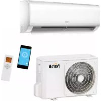
TE FC 3V - Thermostat FERROLI - Free user manual and instructions
Find the device manual for free TE FC 3V FERROLI in PDF.
User questions about TE FC 3V FERROLI
0 question about this device. Answer the ones you know or ask your own.
Ask a new question about this device
Download the instructions for your Thermostat in PDF format for free! Find your manual TE FC 3V - FERROLI and take your electronic device back in hand. On this page are published all the documents necessary for the use of your device. TE FC 3V by FERROLI.
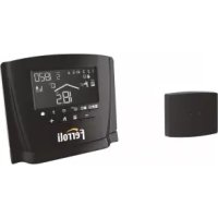
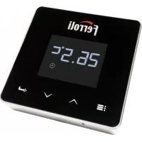
USER MANUAL TE FC 3V FERROLI
EN INSTALLATION AND USER MANUAL
- This manual gives detailed description of the precautions that should be brought to your attention during operation.
- In order to ensure correct service of the wired controller please read this manual carefully before using the unit.
- For convenience of future reference, keep this manual after reading it.
The original documentation is written in English. All other languages are translations.
EN
CONTENTS
1 Quick Operation Process 01
2 Features 01
3 Main Parameters 02
4 Overview 03
5 Basic Setting 04
6 Fan Speed Setting 05
7 Timer Setting 06
8 Child Lock Setting 07
9 Indoor Temperature Display 07
10 Project Commissioning 08
11 Installation 13
EN
1 Quick Operation Process


Mode F#spAeajtGhtEffnpsaritare

1.1 Auxiliary function operation
Timer function:

Timing

Adjust time

Press to confirm timing
Press and hold for 3s to cancel the timing
- ECO function:

Press and hold for 2s


Enable the ECO mode
2 Features

Modbus ChiElecric auxiliary heating mode

ECO setting
Timer function

EN
3 Main Parameters
| Rated voltage 220-240V~, 50/60Hz | |
| Rated Current | Substantially resistive load: max. 1A /output, total: max. 1A Inductive load: max. 0.9A /output, total: max. 1A, PF=0.93 |
| Temperature limit | -15°C to 43°C |
| Humidity | ≤RH90 % |
| Degree of pollution 2 | |
| Action Type 1B.U | |

CAUTION
- Entrust a qualified local technician to perform installation. The user must not install the unit. The unit must be installed by a professional technician.
- Before cleaning or maintenance, ensure the power supply is cut off. Do not use water for washing to prevent electric shocks.
- Do not operate with wet hands to avoid electric shocks.
- Do not use pesticides, disinfectants, or flammable directly on the wired controller as they may damage the device or cause fires.
- Do not try to remove the display panel with your bare hands to avoid electric shocks.
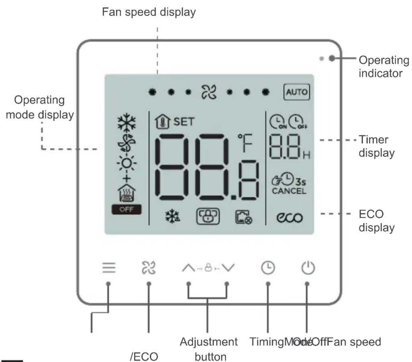
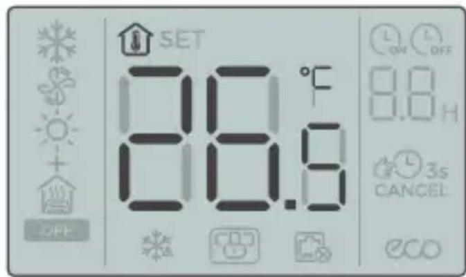
4 Overview
EN
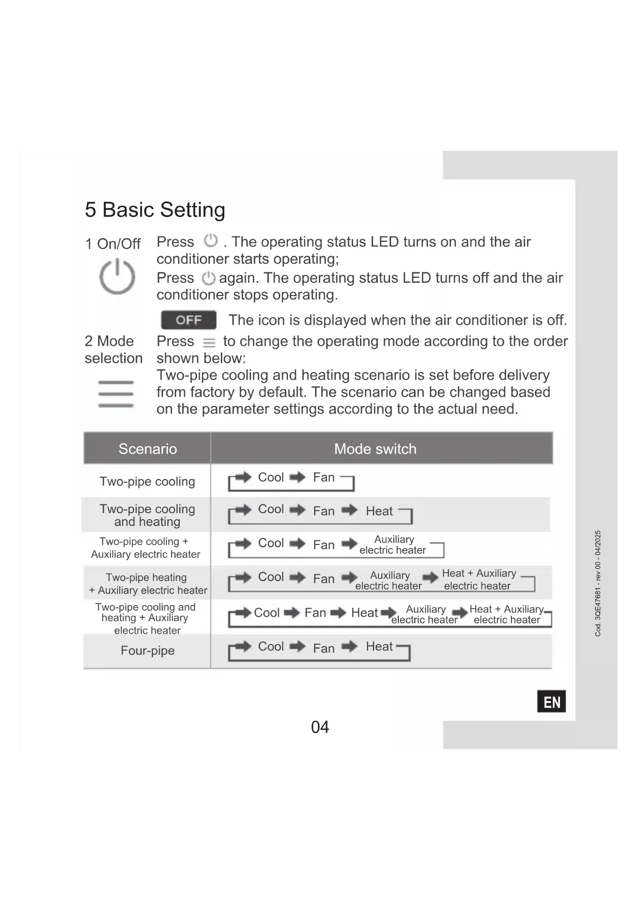
5 Basic Setting
1 On/Off

Press . The operating status LED turns on and the air conditioner starts operating;
Press again. The operating status LED turns off and the air conditioner stops operating.
OFF
The icon is displayed when the air conditioner is off.
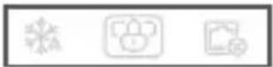
2 Mode selection
Press to change the operating mode according to the order shown below:

Two-pipe cooling and heating scenario is set before delivery from factory by default. The scenario can be changed based on the parameter settings according to the actual need.
| Scenario | Mode switch |
| Two-pipe cooling | →Cool →Fan |
| Two-pipe cooling and heating | →Cool →Fan →Heat |
| Two-pipe cooling + Auxiliary electric heater | →Cool →Fan →Auxiliary electric heater |
| Two-pipe heating + Auxiliary electric heater | →Cool →Fan →Auxiliary electric heater →Heat + Auxiliary electric heater |
| Two-pipe cooling and heating + Auxiliary electric heater | →Cool →Fan →Heat →Auxiliary electric heater →Heat + Auxiliary electric heater |
| Four-pipe | →Cool →Fan →Heat |
EN
3 Temperature setting

Except in the Fan mode, press or to adjust the set temperature indoors. Press and hold the button to increase or decrease the set temperature continuously.
4 ECO setting

Press and hold bottom for 2s to enable ECO mode.
Cooling ECO: 26^ , low fan speed;
Heating + Auxiliary electric heater ECO: 18°C, low fan speed
6 Fan Speed Setting
1 Adjust fan speed

Press to adjust the fan speed, which can be set to High, Normal, Low and Auto.


CAUTION
- After the fan speed is set, it takes time for the air conditioner to respond. It is normal if the air conditioner does not respond to the setting immediately.
EN
7 Timer Setting

1 Timed On setting:
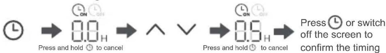
2 Timed Off setting:

3 Cancel timing:
Press and hold Timer for 3s or set the timer to 0.0 to cancel timing.

CAUTION
- Timed Off can be set when the air conditioner is on and Timed On can be set when the air conditioner is off.
EN
8 Child Lock Setting
1 Enable child lock:


Press and hold the two buttons for 1.5s
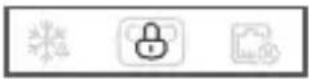
Enable child lock
The wired controller doesn't respond when buttons are pressed and flashes.
2 Disable child lock


Press and hold the two buttons for 1.5s
Disable child lock
9 Indoor Temperature Display
- The indoor temperature is displayed when the screen is off.
EN
10 Project Commissioning
- Touch and hold , 忍 and at the same time for 5s, and the wired controller will restart with its parameters restored to the factory settings.
10.2 Error Display
- When the sensor fails, the LCD displays the error code E1 in the Temperature Setting display area;
- In the Parameter Settings interface, the LCD displays the icon when Modbus communication fails;
- Notify the distributor of the error code. Do not disassemble, modify or repair the air conditioner without authorization.
10.3 Parameter Settings of the Temperature Controller
- Parameters can be set when the unit is on or off.
- Touch and hold and for 3s to enter the parameter settings interface.
- After entering the page for parameter settings, C0 is displayed in the temperature display zone. Press and to switch over to Parameter Code; after selecting Parameter Code, press to enter the specific parameter settings. Press and to set parameters. Press to save the parameters. Press to exit the parameters without saving parameters.
- If no operation is made in 60s, the page will save your parameters and close.
- When it is in the parameter settings page, the wired controller cannot communicate with Modbus.
EN
| Parameter Code | Parameter Name | Parameter Range | Default Value | Remarks |
| C0 | Wired controller address | 01-32 | 01 | |
| C1 | Two-pipe/four-pipe selection | 00:Two-pipe cooling and heating 01:Two-pipe cooling 02:Two-pipe cooling +Auxiliary electric heater 03:Two-pipe heating +Auxiliary electric heater 04:Two-pipe cooling and heating +Auxiliary electric heater 05:Four-pipe | 00 | |
| C2 | ECO cooling temperature setting | 17°C to 30°C / 62°F to 86°F | 26°C / stepping | 0.5°C /1°F |
| C3 | ECO heating temperature setting | 17°C to 30°C / 62°F to 86°F | 18°C / 64°F | Stepping 0.5°C /1°F |
| C4 | Anti-freezing protection | 00:Off 01:Start | 00 | |
| C5 | Anti-freeze temperature setting | 0°C to 20°C / 32°F to 68°F | 5°C / 41°F | Stepping 0.5°C /1°F |
| C6 | 00:4800 01:9600Baud rate setting | 01 | ||
| C7 | Celsius/Fahrenheit | 00:°C 01:°F 00 | ||
| C8 | 00:Off 01:OnButton backlight setting | |||
| C9 | Language | 00:Chinese 01:English 01 | ||
| C10 | Cooling/Fan temperature compensation | 0°C / 0°F | Stepping 0.5°C /1°F | |
| C11 | Heating/Auxiliary electric heater temperature compensation | -10°C to 10°C / -18°F to 18°F | Stepping0.5°C /1°F | |
| C12 | Temperature return difference | 1, 2, 3 (°C) / 2, 4, 6 (°F) 1°C / 2°F | ||
| C13 | Fan always on/always off (After setting temperature) | 00:Always off 01:Always on 0 |
EN
| Parameter Code | Parameter Name | Parameter Range | Default Value | Remarks |
| C14 | Duration of preventing cold/heat wind (seconds) | 0, 5, 10, 15, 30, 60, 90 | 00 | only valid if C15 set 01 |
| C15 | Prevent cold/heat wind Set | 00: No prevent cold wind01: according to Time(C14)02: according to Temp(C16/17) | 02 | |
| C16 | Prevent cold wind Temp | 35 | Read only | show "P0" when on |
| C17 | Prevent heat wind Temp | 20 | Read only | show "P1" when on |
| C18 | Pipe Temp | Read only | show "E2" when senor not connected | |
| C19 | Version | Read only |
| Fault and protection code table | |
| P0 | Set C15 value 01 or 02, prevent cold wind at heating mode operation, fan would stop and display P0, provided that pipe temperaturewere <35℃(C16) or preventing time(C14) hasn't run out. |
| P1 | Set C15 value 01 or 02, prevent hot wind at cooling mode operation, fan would stop and display P1, provided that pipe temperature were >20℃(C17) or preventing time(C14) hasn't run out. |
| E1 | Malfunction of indoor ambient temperature sensor. |
| E2 | Malfunction of pipe temperature sensor when C15 value is set 02. |
10.4 Modbus
- Transmission rate: 9600 bps; Data length: 8 bits; Stop bit: 1 bit; Check bit: no check; Transmission code: hexadecimal value (MODBUS RTU mode); Error detection: CRC-16 (MODBUS RTU mode);
- MODBUS communication IP address of slave unit: 1-32;
Command = 03 : Multi-register read instruction; Command = 06 : Single register write instruction;
Command = 16 : Multi-register write instruction.
EN
| Command | Register Parameter | Name Parameter | Range | Default Value |
| 03 | 1 | Thermostat program version No. | 1~255 | |
| 03 | 2 | Celsius: -50~500; Fahrenheit: 23~122 Room temperature | ||
| 03/06/16 | 3 | Current ON/OFF mode | 0: OFF; 1: ON | |
| 03/06/16 | 4 | Current setting temperature | 17°~30°C / 62°F~86°F | |
| 03/06/16 | 5 | System mode setting | 0: Ventilation; 1: Cooling; 2: Heating; 3: Auxiliary electric heater; 4: Heating + Auxiliary electric heater | 0 |
| 03/06/16 | 6 | Set fan speed 1: Low; 2: Medium; 3: High; 4: Auto | 4 | |
| 03/06/16 | 7 | Fan always on /always off (After setting temperature) | 00: OFF; 01: ON | 0 |
| 03/06/16 | 8 | Select temperature unit | 00:°C degrees Celsius 01:°F degrees Fahrenheit | 0 |
| 03/06/16 | 9 | Cooling/Fan temperature compensation | -10C°~10°C/ -18°F~18°F | 0C° / 0°F |
| 03/06/16 | 10 | Heating/Auxiliary electric heater temperature compensation | -10C°~10°C/ -18°F~18°F | 0C° / 0°F |
| 03/06/16 | 11 | Duration of preventing cold wind (seconds) | 0, 5, 10, 15, 30, 60, 90 | 0 |
| 03/06/16 | 12 | Temperature return difference | 1、2、3 C (°C) / 2、4、6 (°F) | 1C° / 2°F |
| 03/06/16 | 13 | Communication IP address (Modbus) | 01-32 | 1 |
| 03/06/16 | 14 | Whether anti-freezing protection is enabled | 00: OFF; 01: ON | 0 |
| 03/06/16 | 15 | Anti-freezing setting temperature | 0° ~20°C / 32°F~68°F | 5°C / 41°F |
| EN | 03/06/16 | Centralized control locking | 00: OFF; 01: ON | 0 |
| Command | Register Parameter Address | Name Parameter | Range | Default Value |
| 03/06/16 | 17 | System type | 00: Two-pipe cooling and heating01: Two-pipe cooling02: Two-pipe cooling +Electric auxiliary heating03: Two-pipe heating +Electric auxiliary heating04: Two-pipe cooling and heating+Electric auxiliary heating05: Four-pipe | 0 |
| 03 | 18 | Restore factory settings | 0: General; 1: Restore factory settings | 0 |
| 03 19 | High fan speed status | 00: OFF; 01: ON | 0 | |
| 03 20 | Medium fan speed status | 00: OFF; 01: ON | 0 | |
| 03 21 | Low fan speed status | 00: OFF; 01: ON | 0 | |
| 03 22 | Valve 1 status | 00: OFF; 01: ON | 0 | |
| 03 23 | Valve 2 status | 00: OFF; 01: ON | 0 | |
| 03/06/16 | 24 | Prevent cold/heat wind Set | 00: No prevent cold wind01: according to Time(C14)02: according to Temp(C16/17) | 0 |
| 03 | 25 | Prevent cold wind Temp | 35°C / 95°F | 35°C / 95°F |
| 03 | 26 | Prevent heat wind Temp | 20°C / 68°F | 20°C / 68°F |
| 03 | 27 | Pipe Temp | 0~55°C (32~131°F) | |

CAUTION
- The minimum interval of data packet is 100ms . In case of excessive data in a single data packet, adjust the time interval appropriately.
EN

CAUTION
- The default status of Valve1 and Valve 2 will depending on the system state.
- The numerical analysis method is different in different temperature systems. At Celsius, the value of the register is 10 times the actual temperature. When setting the register value, the input value should be an integer multiple of 5; In Fahrenheit, the value
11 Installation
11.1 Installation Precautions
- To ensure correct installation, read the "Installation" section of this manual.
- The content provided here covers warnings, which contains important information about safety that must be followed.

CAUTION
- Entrust the local distributor or local service agent to appoint a qualified technician to perform installation. The user must not install the unit.
- Do not disassemble and assemble the product without permission.
- The wiring must be compatible with the wired controller current.
- Use the specified cables, and do not place heavy object on the wiring terminals.
EN
11.2 Installation Accessories
Please check that you have all the following parts.
| No. | Name | Qty | Remarks |
| 1 | Wired controller | 1 | |
| 2 | Philips head screw, M4×25 | 2 | Used to install the wired controller on the electrical box |
| 3 | Installation & Owner's Manual | 1 | |
| 4 | Plastic support bar | 2 | Used to install the wired controller on the electrical box |
| 5 | Pipe temperature sensor connection line | 1 | To prevent cold/hot wind according to this sensor, it is supposed to set C15 to 02. |
Prepare the following parts in the field:
| No. | Name | Qty | Remarks |
| 1 | Installation box(cassette type) | 1 | General specifications of the installation box, which is embedded into the wall |
| 2 | Shielded 3-core cable | 1 | RVVP-0.5 mm²×3, embedded into the wall |
| 3 | Control cable (with the null and live wires) | 1 | 1.5 mm²×7, embedded into the wall |
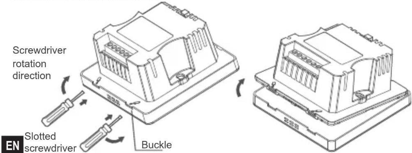
| 4 | Small slotted screwdriver | 1 | Used to install the slotted head screws and remove the bottom cover of the wired controller |
EN
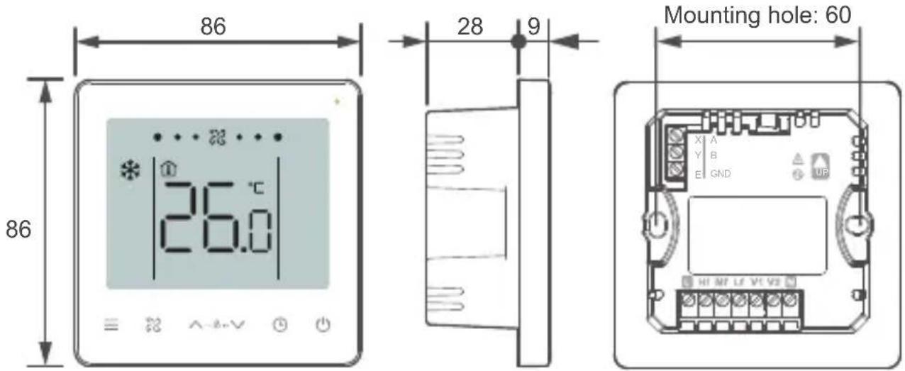
11.3 Product Dimensions (mm)
11.4 Installation Method
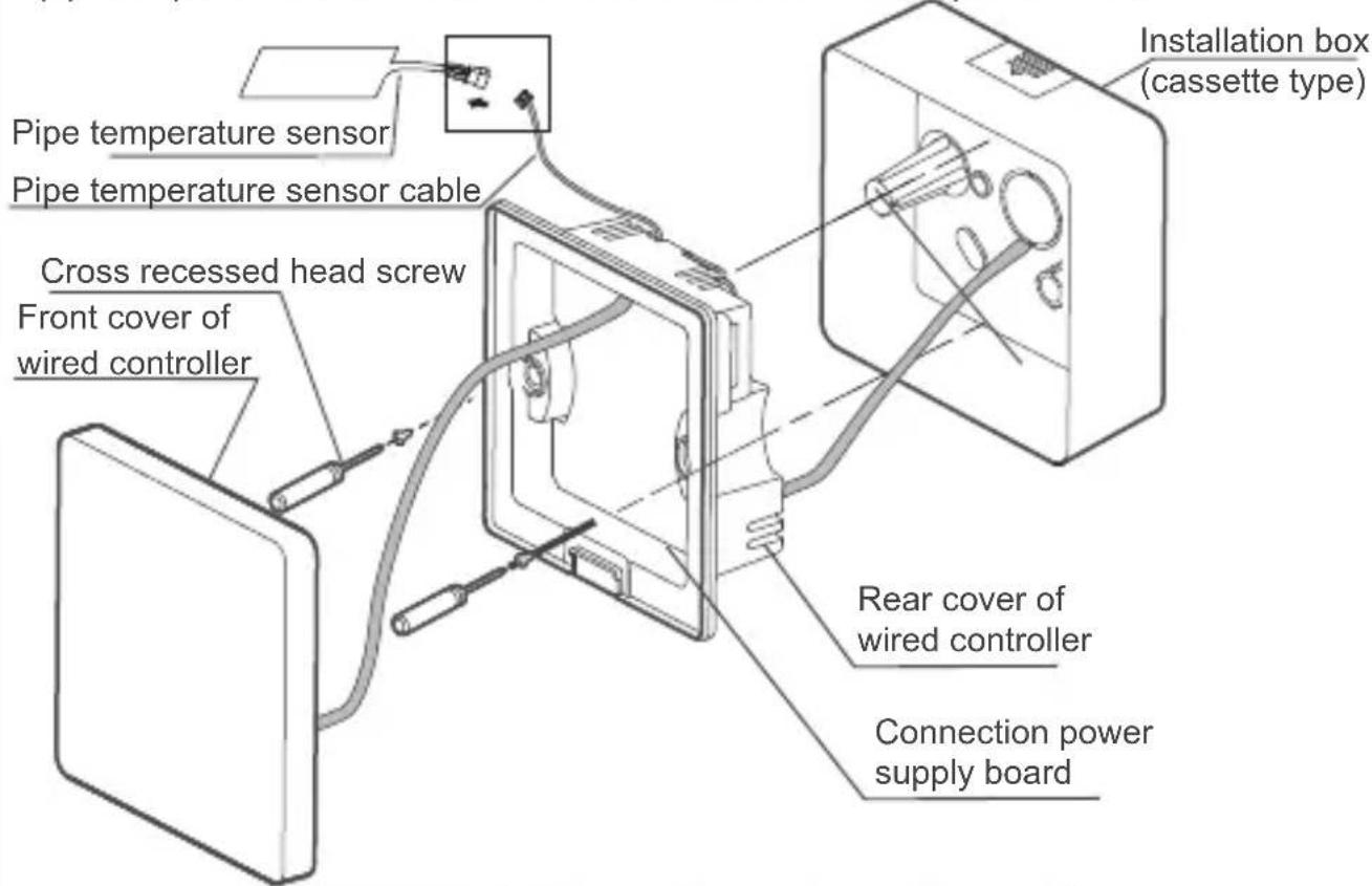
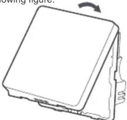
- Remove rear cover of the wired controller: insert a slotted-head screwdriver into the bottom buckle of the wired controller, and rotate in the direction indicated to remove the rear cover. Remove the flat cable connecting the front and rear PCBs and remove the front cover of the wired controller.
- Install support bars: Adjust the lengths of the two plastic support bars in the accessories. Ensure that the rear cover of the wired controller stays level with the wall when installed on the screw post of installation box (cassette type).
Screw post of the installation of the two plastic support bars
box (cassette type)

Use a cutting tool to adjust the lengths of the two plastic support bars
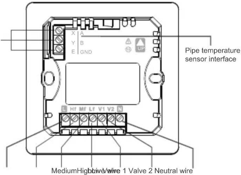
- Connect the other end of the pipe temperature sensor cable to the sensor.
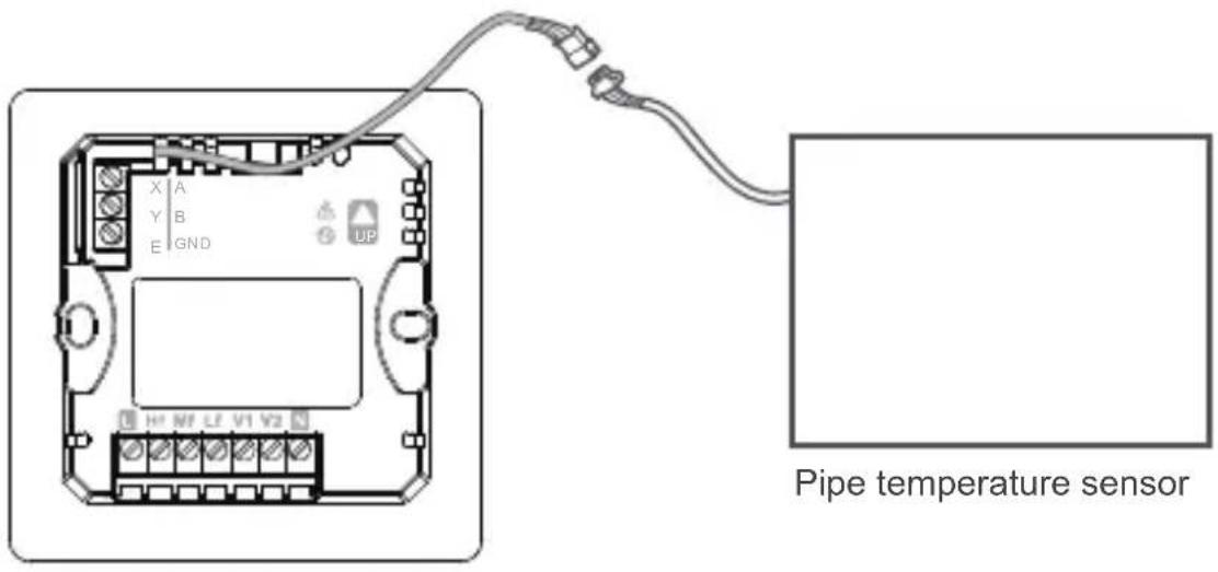
Pipe temperature sensor
EN
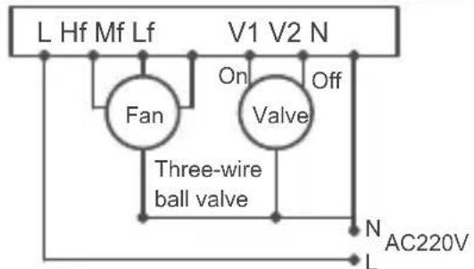
- Wiring: Connect the cables according to the following wiring drawing
485 communication interface

PROHIBIT
- This product must be installed by a specialized technician. Do not connect cables when the unit is active.
- Do not connect the neutral and live wires to the X/Y/E ends. Otherwise, the wired controller will be burnt.

WARNING
EN
- Check the wiring before powering on the unit. Wrong wiring may damage the wired controller.
Installation and Wiring diagram
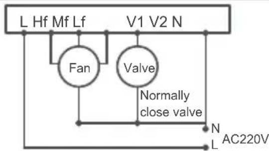
Two-pipe cooling/cooling and heating
Two-pipe cooling/cooling and heating
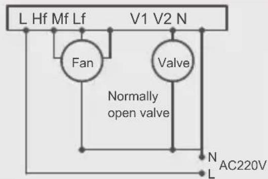
Two-pipe cooling/cooling and heating
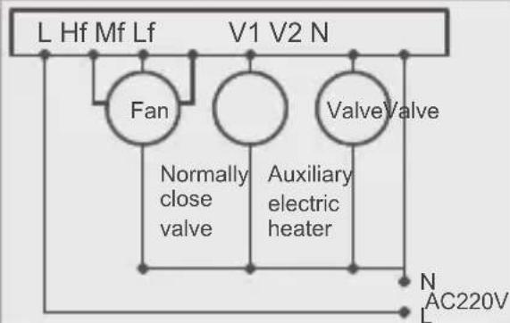
Two-pipe heating + Auxiliary electric heater
Two-pipe cooling + Auxiliary electric heater
Two-pipe cooling and heating + Auxiliary
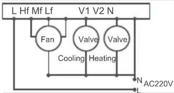
Four-pipe
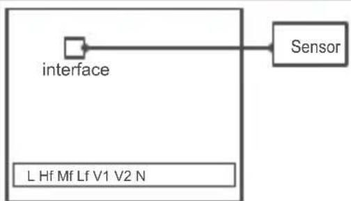
Add prevent cold wind function
EN
- Insert the cable of the rear cover into the installation box (cassette type). Use pan head screws to fix the rear cover of the wired controller on the installation box (cassette type); connect the flat cable that connects the front and rear PCBs.Use the pipe temperature sensor cable to connect the sensor to the power board.

WARNING
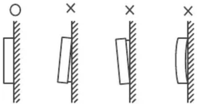
- Do not overtighten the pan head screws, otherwise the rear cover of the wired controller may deform and cannot be levelled on the wall surface, which makes it difficult to install or not securely installed.
EN
- Buckle the front cover of the wired controller on the rear cover as shown in the following figure.
First buckle the upper ends of the front and rear covers of the wired controller.
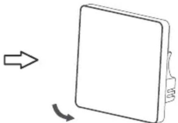
Then buckle the lower ends of the front and rear covers of the wired controller.

WARNING
- Make sure that no cables are clamped when buckling the front and rear covers.
- The front and rear covers should be installed correctly. Otherwise, the front and rear covers may get loose and fall apart.
EN