
Romeo N - Thermostat FERROLI - Free user manual and instructions
Find the device manual for free Romeo N FERROLI in PDF.
| Product Type | Programmable room thermostat |
| Brand | Ferroli |
| Model | Romeo N |
| Main functions | Weekly programming, summer/winter/frost protection mode, holiday function, preheat, climatic compensation (with optional outdoor sensor), domestic hot water management |
| Display | Backlit LCD screen with icons and numerical indications |
| Power supply | Via the connection cable to the boiler (low voltage); OpenTherm protocol |
| Dimensions (approx.) | 140 x 90 x 30 mm |
| Weight (approx.) | 250 g |
| Room temperature range | 5 °C to 35 °C (displayed setting: 7 °C to 32.5 °C in 0.1 °C steps) |
| Heating flow temperature range | Adjustable via the boiler (displayed and modifiable on the thermostat) |
| Time programming | Up to 6 time periods per day, customizable for each day of the week |
| Holiday function | Heating (and DHW if tank) shutdown from 1 hour to 45 days |
| Frost protection | Maintains room temperature at minimum 5 °C |
| Communication | OpenTherm protocol (compatible with equipped Ferroli boilers) |
| Auxiliary input | Phone contact (AUX terminals) to force shutdown or a fixed temperature |
| Installation | Wall-mounted at about 1.5 m from the floor, bipolar cable max. 50 m |
| Maintenance and cleaning | Clean with a soft dry cloth; do not use abrasive products or solvents |
| Safety | Probe fault detection (E92, E93) with automatic heating shutdown |
| Reset | Simultaneously press the + and - keys for 10 seconds to return to factory settings |
| Warranty | See warranty provided with the device or the Ferroli website |
Frequently Asked Questions - Romeo N FERROLI
User questions about Romeo N FERROLI
0 question about this device. Answer the ones you know or ask your own.
Ask a new question about this device
Download the instructions for your Thermostat in PDF format for free! Find your manual Romeo N - FERROLI and take your electronic device back in hand. On this page are published all the documents necessary for the use of your device. Romeo N by FERROLI.
USER MANUAL Romeo N FERROLI
line
| Temperature esterna (°C) | Temperature di mandata impianto (°C) | | :--- | :--- | | -10 | 85 | | -5 | 75 | | 0 | 65 | | 5 | 55 | | 10 | 45 | | 15 | 35 | | 20 | 30 | The chart displays a single data series with multiple lines labeled 1 through 10, indicating a linear trend of temperature change over time. The x-axis represents 'Temperature esterna' in degrees Celsius, and the y-axis represents 'Temperature di mandata impianto'. There is no additional data series or labels provided in the image.natural_image
Line drawing of a device with labeled component A, no text or symbols present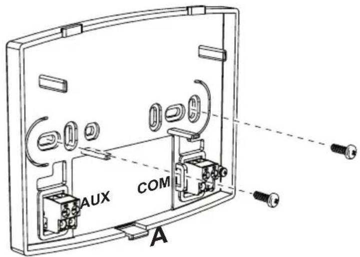
line
| Temperature exterior (°C) | 1 | 2 | 3 | 4 | 5 | 6 | 7 | 8 | 9 | 10 | |---|---|---|---|---|---|---|---|---|---|---| | -20 | 30 | 40 | 50 | 60 | 70 | 80 | 85 | 90 | 95 | 100 | | -10 | 35 | 45 | 55 | 65 | 75 | 85 | 90 | 95 | 100 | 105 | | 0 | 40 | 50 | 60 | 70 | 80 | 90 | 95 | 100 | 105 | 110 | | 10 | 45 | 55 | 65 | 75 | 85 | 95 | 100 | 105 | 110 | 115 | | 20 | 50 | 60 | 70 | 80 | 90 | 100 | 105 | 110 | 115 | 120 | The chart displays a line graph with no explicit title or axis labels, but it plots temperature values against temperature exterior in degrees Celsius. The legend is labeled with numbers from 1 to 10, likely indicating a series of discrete data points. The x-axis label 'Temperatura exterior' appears to be the temperature value at the end of the scale.natural_image
Line drawing of a handheld electronic device with labeled component A (no text or symbols on the device itself)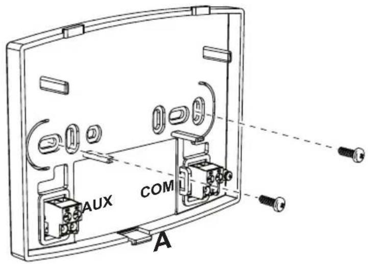
natural_image
Line drawing of a device with labeled component A, showing a handle and internal components (no text or symbols beyond label)
- Remote control overview....119
- Configure and operate the remote control in 4 easy steps....121
(Step 1) Correct setting of time and day ......121
(Step 2) Setting the automatic weekly program....121
(Step 3) Operation mode selection....124
(Step 4) DHW - Heating temperature adjustment....125
Special Functions....126
Vacation Function....126
User parameter editing 127
Enable DHW programming....129
Pre-Heating function 130
Maximum number of daily time bands 131
Heating minimum temperature....131
System filling....132
Temperature unit of measure selection....132
Room temperature reading correction 133
Telephone contact input 133
Protocol type....134
Set Max CH and Set DHW....134
Contrast (for versions with backlight)....135
Lighting duration (for versions with backlight)....135
Other functions....136
Information menu....136
Power failures 136
Diagnostics 137
Room temperature probe fault 137
External temperature probe fault 137
Restoring factory settings 137
Installation....138
Technical characteristics and default settings....139
- REMOTE CONTROL OVERVIEW
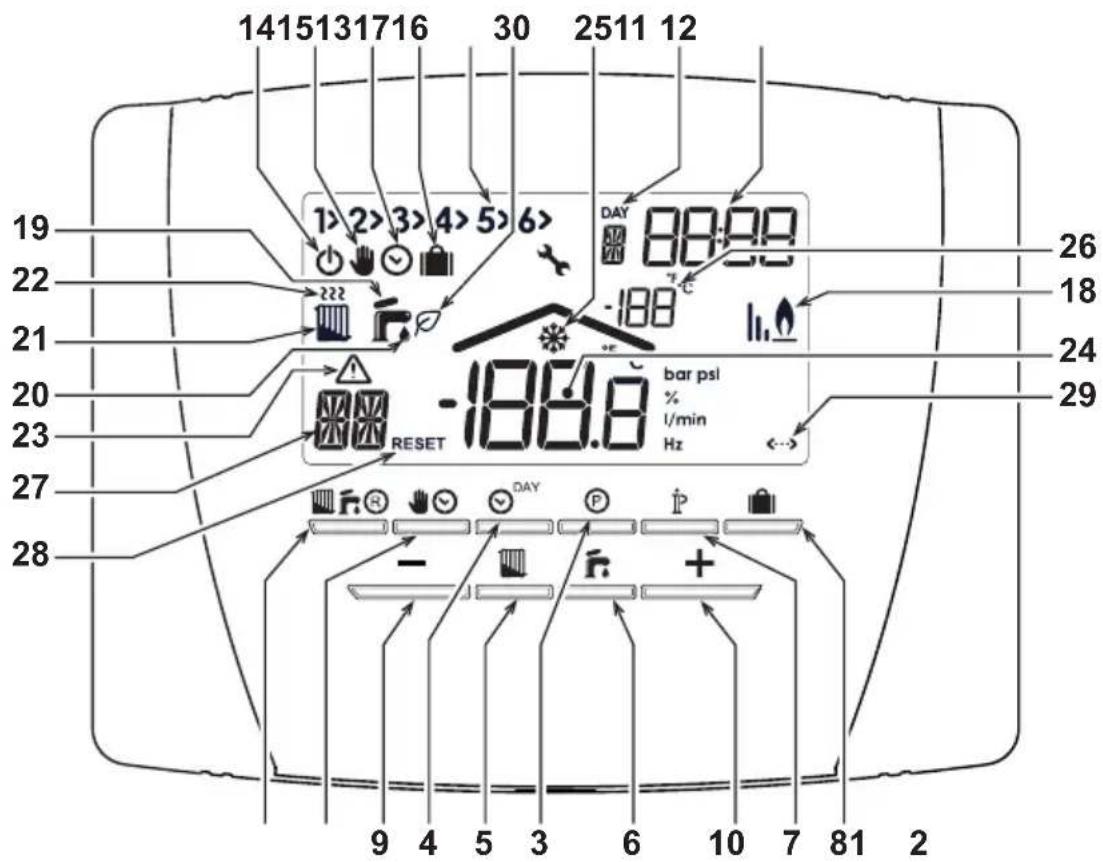
fig. 1
code 3541Z220 - Rev. 05 - 12/2021
Legend
1 OFF, summer winter mode selection/fault reset button
2 Automatic/manual mode heating button
3 Heating - DHW programming button
4 Time and day setting button
5 Heating temperature adjustment button
6 DHW temperature adjustment button
7 User information/settings button
8 Vacation function/copy heating - DHW program day button
9 Room temperature manual decrease button
10 Room temperature manual increase button
11 Heating program time bands
12 Day of the week
13 Hours and minutes
14 OFF mode
15 Manual heating operation
16 Automatic heating operation indication
17 Vacation function
18 Burner on and actual power
19 Summer mode
20 DHW operation
21 Winter mode
22 Heating operation
23 Fault indication
24 Room temperature
25 Room frost protection
26 External temperature
(only with optional external probe connected)
27 Type of fault / Information
28 Fault RESET indication (blinking)
29 OpenTherm communication present
30 DHW ECO in progress
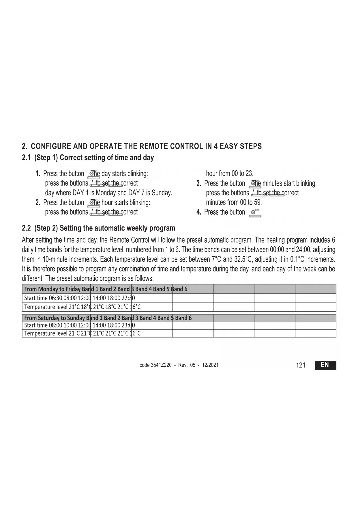
2. CONFIGURE AND OPERATE THE REMOTE CONTROL IN 4 EASY STEPS
2.1 (Step 1) Correct setting of time and day
- Press the button. The day starts blinking: press the buttons / to set the correct day where DAY 1 is Monday and DAY 7 is Sunday.
- Press the button . The hour starts blinking: press the buttons / to set the correct
hour from 00 to 23.
-
Press the button . The minutes start blinking: press the buttons / to set the correct minutes from 00 to 59.
-
Press the button . DAY
2.2 (Step 2) Setting the automatic weekly program
After setting the time and day, the Remote Control will follow the preset automatic program. The heating program includes 6 daily time bands for the temperature level, numbered from 1 to 6. The time bands can be set between 00:00 and 24:00, adjusting them in 10-minute increments. Each temperature level can be set between 7°C and 32.5°C, adjusting it in 0.1°C increments. It is therefore possible to program any combination of time and temperature during the day, and each day of the week can be different. The preset automatic program is as follows:
| From Monday to Friday Band 1 Band 2 Band 3 Band 4 Band 5 Band 6 | |||||
| Start time 06:30 08:00 12:00 | 14:00 18:00 22:30 | ||||
| Temperature level 21°C 18°C | 21°C 18°C 21°C 16°C | ||||
| From Saturday to Sunday Band 1 Band 2 Band 3 Band 4 Band 5 Band 6 | |||||
| Start time 08:00 10:00 12:00 | 14:00 18:00 23:00 | ||||
| Temperature level 21°C 21°C | 21°C 21°C 21°C 16°C | ||||
Follow the instructions below to change the preset automatic program.
-
Press the button Ⓟ. If DHW programming has been enabled, select the radiator symbol with the buttons / + and confirm with the button Ⓟ. The 6 daily time bands blink and the number 1 of DAY 1 is followed by an arrow (1) to indicate that the time band 1 of Monday can be changed.
-
Press the button ⚠The hour and minutes start blinking: press the buttons / + - to change the time band start time in 10-minute increments. By keeping the button pressed the hour and minutes will change rapidly.
-
Press the button ⚠ . The indication of room temperature inside the house starts blinking: press the buttons /— to change the temperature level in 0.1°C increments. By keeping the button pressed the temperature will change rapidly.
-
Press the button 📋 The 6 daily time bands blink.
-
Then press the button to call up the Monday time slot 2 on the display, which can be modified by repeating points 2 to 4.
-
The remaining time bands can be displayed by selecting bands 3, 4, 5 or 6 with the buttons / + - , repeating point 5.
-
It is now possible to choose program setting for the next day:
a. Press the button 📋 DAY to display DAY 2. The Tuesday program can be modified by repeating points 2 to 6.
b. Press the button 📄 to copy the Monday program to Tuesday. To copy the same program also to the following days of the week, press the button 📄 repeatedly.
Attention! Set the program making sure that each band has a different start time.
Personal program annotation
| Band 1 Band | 2 Band 3 Band | 4 Band 5 Band 6 | ||||
| Monday | Start time | |||||
| Temperature level | ||||||
| Tuesday | Start time | |||||
| Temperature level | ||||||
| Wednesday | Start time | |||||
| Temperature level | ||||||
| Thursday | Start time | |||||
| Temperature level | ||||||
| Friday | Start time | |||||
| Temperature level | ||||||
| Saturday | Start time | |||||
| Temperature level | ||||||
| Sunday | Start time | |||||
| Temperature level | ||||||
2.3 (Step 3) Operation mode selection
OFF mode selection
If planning to leave the house for a long period (also see Vacation Function), or just to turn the heating off, press the button displaying the symbol ⏻. Heating is turned off and activated only if the room temperature falls below 5°C: frost protection function. If equipped with storage, the boiler will not deliver domestic hot water; the instantaneous-type boiler will deliver domestic hot water.
Summer mode selection
To turn heating off, but maintaining the delivery of domestic hot water, press the button 📄, displaying the symbol 🌐. Heating is turned off and activated only if the room temperature falls below 5°C: frost protection function. The boiler, of any type, will deliver domestic hot water.
Winter mode selection
To re-enable heating and return to the previously set operation mode, press the button again, displaying the symbol. The boiler, of any type, will deliver domestic hot water.

Automatic heating operation (in Winter mode)
Press the button, displaying the symbol. The Remote Control will work according to the automatic weekly program, displaying the 6 time bands. The band indicated by an arrow will be active at that moment. If the display does not show an arrow, it means that the actual time is between 00:00 and the start of time band 1.
Set temperature level exclusion
During automatic operation the room temperature value can be temporarily changed by pressing the buttons / + - in 0.1°C increments. By keeping the button pressed the temperature will change rapidly. The exclusion function, indicated on the display by the symbol blinking, will be canceled at the first time band change.
EN
124
code 3541Z220 - Rev. 05 - 12/2021
Manual heating operation (in Winter mode)
To use the Remote Control at a fixed room temperature level, press the button 📁 displaying the symbol ⚪ (the 6 time bands are not displayed). Then set the room temperature value by pressing the buttons / + in 0.1°C increments. By keeping the button pressed the temperature will change rapidly. Manual operation will be maintained until another operation mode is selected.
2.4 (Step 4) DHW - Heating temperature adjustment
Heating - Press the button ☐: the display shows the actual heating circuit water temperature setting, adjustable using the buttons /+ - in 1°C increments. Press any button to exit the menu.
DHW - Press the button ☐: the display shows the actual DHW temperature setting, adjustable using the buttons / + in 1°C increments. Press any button to exit the menu.
3. SPECIAL FUNCTIONS
3.1 Vacation Function
It has the function of turning heating off (also DHW production if the boiler is equipped with storage) for a certain period of time, from 1 hour to 45 days, adjusting it in 1-hour increments. This saves energy and related costs when away from home, whereas the previously set operation mode resumes when the Vacation function ends. Heating is activated only if the room temperature falls below 5^ C: frost protection function.
Follow the instructions below to activate and set the Vacation function.
-
Press the button 📄. The symbol 📋 starts blinking, the symbol 🌐 appears (steady) and the hour and minutes indication becomes -00:01, which represents the time remaining at the end of the Vacation function.
-
Press the buttons L + to increase the time remaining to the end of the Vacation function in 1-hour increments (-00:01 means 1 hour; -45:00 means 45 days). By keeping the button pressed the time and days will change rapidly.
-
During the Vacation function the display will continue to show the time remaining to the end of the function. To cancel the Vacation function, press the button or any other button associated with a different operating mode.
3.2 User parameter editing
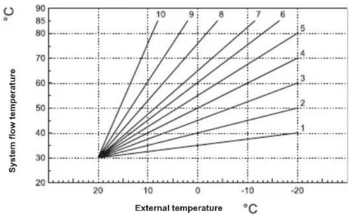
Sliding temperature - Climatic compensation curve with outside temperature
By installing the external probe (optional) the control system is able to work with Sliding Temperature. The external probe must be connected to the boiler board: see the relevant manual. In this mode the heating system temperature is adjusted according to the outside weather conditions, in order to ensure high comfort and energy saving throughout the year. In particular, as the outside temperature increases, the system flow temperature decreases according to a specific compensation curve. With Sliding Temperature adjustment, the temperature set via the "Heating temperature adjustment" becomes the maximum system flow temperature. It is advisable to set a maximum value to allow system adjustment throughout its useful operating range. The compensation curve can be adjusted from 1 to 10 according to the following graph.
line
| External temperature (°C) | System flow temperature (°C) | | ------------------------- | ---------------------------- | | -20 | 40 | | -10 | 50 | | 0 | 60 | | 10 | 70 | | 20 | 80 | | 30 | 90 |- Press the button for 3 seconds.
- The display shows parameter CU.
Press the buttons / to change the compensation curve in increments of 1 unit. By keeping the button pressed the value will change rapidly. - Press any other button to exit the menu.
By adjusting the curve to 0 the Sliding Temperature is disabled.
The system must be adjusted during installation by qualified personnel. The user can still make further adjustments for better comfort. If the room temperature is lower than the desired value, it is advisable to set a higher order curve and vice versa. Proceed by increasing or decreasing in steps of one and check the result in the room.
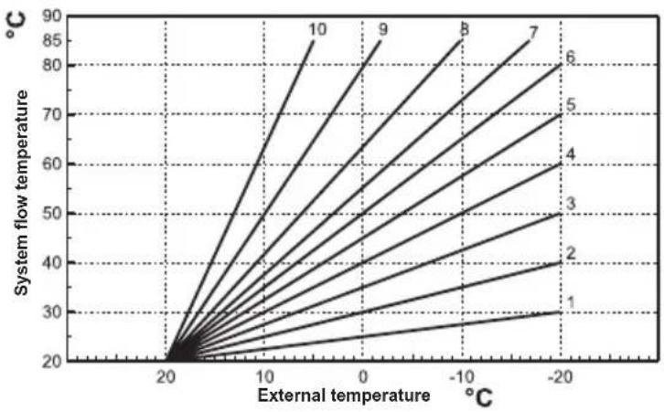
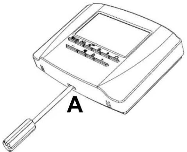
Once the Compensation curve is set, it is possible to adjust the parallel offset of curves from 20 to 40 as shown in the following graphs:
line
| External temperature (°C) | System flow temperature (°C) | | -------------------------- | ----------------------------- | | -20 | 30 | | -10 | 40 | | 0 | 50 | | 10 | 60 | | 20 | 70 | | 30 | 80 | | 40 | 90 | | 50 | 85 | | 60 | 80 | | 70 | 75 | | 80 | 70 | | 90 | 65 | | 100 | 60 |- Press the button for 3 seconds.
- The display shows parameter CU.
- Press the button until parameter OF is displayed.
- Press the buttons / to modify the parallel offset of curves in 1°C increments. By
line
| External temperature (°C) | System flow temperature (°C) | | -------------------------- | ----------------------------- | | -20 | 50 | | -10 | 60 | | 0 | 70 | | 10 | 80 | | 20 | 90 |keeping the button pressed the value will change rapidly.
- Press any other button to exit the menu.
Sliding temperature - Compensation according to room temperature.
As the room temperature approaches the set point, the temperature of the heating system is further adjusted in order to reach the desired value as precisely as possible, without excess heat and wasted energy, thereby significantly improving user comfort.
Follow the instructions below to enable DHW programming.
- Press the button for 3 seconds.
- The display shows parameter CU.
-
Press the button until parameter P1 is displayed.
Set the desired value using the buttons / .
0 = Program disabled, continuous comfort both in summer and winter.
1 = Program enabled only in winter
2 = Program enabled in summer and winter
3 = Program disabled, continuous economy both in summer and winter -
Press any other button to exit the menu.
To set the automatic weekly program, proceed as described in par. "Phase2. Setting the automatic weekly program", selecting the faucet symbol at point "1" and considering that at point "3" EC (Economy) or CO (Comfort) will be set instead of a temperature value. In fact, the remote control has a weekly time programmer based on two levels: during COMFORT level the boiler will keep storage at the set temperature; during the Economy level the boiler will not deliver domestic hot water. Regarding the type of storage, refer to the boiler documentation.
Attention: Make sure the remote control is switched to Winter mode and automatic operation.
3.4 Pre-Heating function
This function is active only if automatic heating mode has been selected.
When set to Automatic, the function anticipates the heating system start time (not before 00:00 of the same day) so that the room temperature set by the user is reached at the start of the programmed band. The Remote Control calculates a first hypothetical Pre-activation time: if the programmed room temperature is reached in a shorter time than the calculated one, the Pre-Heating time will be decreased and vice versa. In this way self-learning is created, for determining the shortest Pre-activation time necessary. The Remote Control also offers the possibility of setting a fixed Pre-Heating ramp: in this case the room temperature will be raised by 3°C per hour.
The automatic heating program should therefore be programmed according to the time when warmth is wanted, and not the desired heating system start time.
Follow the instructions below to activate or deactivate this function.
- Press the button for 3 seconds.
- The display shows parameter CU.
- Press the button repeatedly until parameter P2 is displayed.
Set to 0 using the buttons +/- to deactivate Pre-Heating. Set to 1 using the buttons +/- to activate Automatic Pre-Heating. Set to 2 using the buttons +/- to activate Pre-Heating with fixed ramp of 3°C per hour.
- Press any other button to exit the menu.
During the pre-heating function, the room temperature ^ C symbol blinks.
The pre-heating function ends when the difference between the programmed and actual room temperature is less than 0.5^ C.
3.5 Maximum number of daily time bands
The heating program includes 6 daily time bands for the temperature level, numbered from 1 to 6. If necessary, they can be reduced to a minimum of 2.
- Press the button for 3 seconds.
- The display shows parameter CU.
- Press the button until parameter P3 is displayed.
Press the buttons +/ to change the number of daily time bands from 2 to 6.
- Press any other button to exit the menu.
3.6 Heating minimum temperature
Follow the instructions below to set the heating circuit water minimum value in steps of 1^ C.
- Press the button for 3 seconds.
- The display shows parameter CU.
- Press the button repeatedly until parameter P4is displayed.
Press the buttons +/- to adjust the parameter in 1°C increments. By keeping the button pressed the value will change rapidly.
- Press any other button to exit the menu.
3.7 System filling
This function manages the operation mode of the electric device for filling the water circuit in certain boiler models.
- Press the button for 3 seconds.
- The display shows parameter CU.
- Press the button repeatedly until parameter P5 is displayed.
Set to 0 using the buttons +/- to deactivate the electric filling device. Set to 1 using the buttons +/- to activate manual system filling. Set to 2 using the buttons / to activate automatic system filling.
- Press any other button to exit the menu.
Attention: Set manual filling on the boiler control board. In manual operation and if the sensor installed in the boiler detects insufficient pressure, the bar icon will blink on the display; pressing the button will activate the special solenoid valve. During manual or automatic system loading, the bar icon will become steady. Once the nominal pressure has been re-established, the remote control will return to the normal display.
3.8 Temperature unit of measure selection
Follow the instructions below to use the Remote Control in °C or in °F.
- Press the button for 3 seconds.
- The display shows parameter CU.
- Press the button repeatedly until parameter P6 is displayed.
Set to 0 using the buttons / to select °C.
Set to 1 using the buttons / to select °F.
- Press any other button to exit the menu.
EN
3.9 Room temperature reading correction
Follow the instructions below to correct the room temperature reading between -2^ and +2^ in steps of 0.1^ .
- Press the button for 3 seconds.
- The display shows parameter CU.
- Press the button repeatedly until parameter P7 is displayed.
Use the buttons / to adjust the parameter in 0.1°C increments. - Press any other button to exit the menu.
3.10 Telephone contact input
Normal operation of the Remote Control is ensured as long as the telephone contact remains open. The closing of this contact, indicated on the display with the symbols < >, can be used to force the Remote Control to switch off the heating or to adjust the room temperature to a fixed pre-set value.
Follow the instructions below to set the two functions.
- Press the button for 3 seconds.
- The display shows parameter CU.
- Press the button repeatedly until parameter P8 is displayed.
Set to 0 using the buttons / to turn heating off when the contact is closed.
Set to 1 using the buttons +/– to adjust the room temperature to a fixed pre-set value (via the next parameter P9) when the contact closes. - Press the button
- The display shows parameter P9.
Set the room temperature value that the Remote Control will regulate when the contact is closed (if parameter P8 has been set to 1) by pressing the buttons + / in 0.1°C increments. By keeping the button pressed the temperature will change rapidly.
- Press any other button to exit the menu.
Changing the Remote Control operation mode at telephone contact opening or closing can occur with a maximum time of 60 seconds.
3.11 Protocol type
Follow the instructions below to check the type of protocol used.
- Press the button for 3 seconds.
- The display shows parameter CU.
- Press the button until parameter OT is displayed.
- Check that it is set to "1".
3.12 Set Max CH and Set DHW
Follow the instructions below to check if the heating and DHW set points can be both read and written in the boiler (0 = default), or only written (1).
- Press the button for 3 seconds.
- The display shows parameter CU.
- Press the button until parameter FS is displayed.
- Check that it is set to "1".
3.13 Contrast (for versions with backlight)
To change the display contrast, follow the instructions below.
- Press the button for 3 seconds.
- The display shows parameter CU.
- Press the button repeatedly until parameter D1 is displayed.
- Use the buttons / to adjust the contrast.
3.14 Lighting duration (for versions with backlight)
To change the backlight duration, follow the instructions below
- Press the button for 3 seconds.
- The display shows parameter CU.
- Press the button repeatedly until parameter D2 is displayed.
- Use the buttons / to modify its duration in seconds.
4. OTHER FUNCTIONS
4.1 Information menu
The remote control can communicate to the user some useful information on boiler status. Each press of the button allows the cyclical display of the following information:
T1 Heating circuit flow water temperature
T2 DHW temperature
T3 Heating circuit return water temperature (Only for boilers equipped with sensor)
T4 Flow water temperature setpoint calculated by the remote control
P5 Actual burner power
F6 Actual fan speed (Only for condensing boilers)
F7 Actual DHW flow (Only for instantaneous boilers equipped with flow meter)
P8 Actual system pressure (Only for boilers equipped with pressure sensor)
M Remote control model
V Remote control software version
Press any other button to exit the menu.
4.2 Power failures
The remote control provides for storing the operation mode and calendar updating (day, hour and minutes) in case of a power failure. The charging reserve is 5 hours minimum (guaranteed only if the remote control remains electrically fed for at least 1 hour). Otherwise, it is necessary to reset the current day, hour and minutes and then the operation mode.
4.3 Diagnostics
The remote control continuously monitors boiler status and signals any faults by activating the alarm icon and an error code on the display: for the description of the fault, refer to the boiler documentation.
There are faults that cause permanent shutdowns (indicated with the letter "A" and the symbol RESET): to restore operation, just press the button ☐.
Other faults cause temporary shutdowns (indicated with the letter "F") which are automatically reset as soon as the value returns within the boiler's normal operating range.
4.4 Room temperature probe fault
If the Remote Control room temperature probe is faulty, the display activates fault E92 and the symbol ▲. Heating is turned off.
4.5 External temperature probe fault
In Sliding Temperature mode, if the external temperature probe (optional) is faulty, the display activates fault E93 and the symbol △. The adjustment temperature becomes fixed at the "Heating temperature adjustment" value. To eliminate the fault, restore the external probe or disable the Sliding Temperature adjustment.
4.6 Restoring factory settings
Attention! With this procedure all the Remote Control parameters will be reset to the factory value. It will therefore be necessary to repeat the procedure for the automatic weekly program and reset the user parameters.
Press the buttons /+ together for 10 seconds: only the message RE blinking is displayed. Releasing the buttons at any time before the end of the 10 seconds interrupts the procedure. After the reset, the Remote Control activates all the symbols on the display.
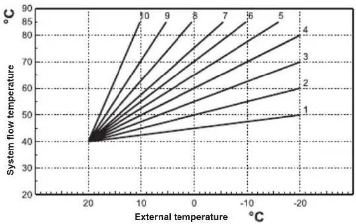
4.7 Installation
The Remote Control must be secured to the wall, at about 1.5 m above the floor, in a place away from entrance doors, windows or heat sources that can affect the room temperature. Before installing, disconnect the power to the boiler. Remove the front part of the Remote Control by prising with a screwdriver at points A. Then secure the back of the Remote Control to the wall with the set of fastening screws provided, making sure to run the 2 wires inside the holes located above the terminals. Use the "COM" terminals for the electrical connection. If the telephone contact (voltage-free contact) has to be connected, use the "AUX" terminals. Reinsert the front part of the Remote Control
natural_image
Line drawing of a device with a handle and labeled component A (no text or symbols on the device itself)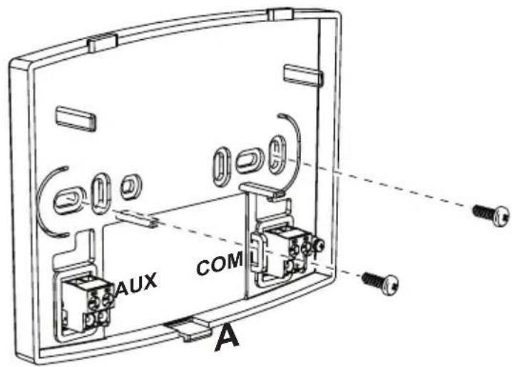
Use a bipolar cable (2x0.75mm2, max 2x2.5mm2) making sure its path is not the same as that of the mains power cables. The maximum cable length must not exceed 50m.
EN
- TECHNICAL CHARACTERISTICS AND DEFAULT SETTINGS
| Time setting 12:00 | ||
| Day setting Day 1=Monday | ||
| Operation mode Automatic | ||
| Manual heating temperature 20°C | ||
| Room frost protection temperature 5°C | ||
| CU Compensation curve 0=Deactivated | ||
| OF Curve parallel offset 30°C | ||
| P1 Enable DHW programming 0=Deactivated | ||
| P2 Pre-Heating function 0=Deactivated | ||
| P3 Maximum number of daily time bands 6 | ||
| P4 Heating minimum temperature | - | |
| P5 System filling | 0=Deactivated | |
| P6 Temperature unit of measure selection | 0=°C | |
| P7 Room temperature reading correction | 0 | |
| P8 Telephone contact input operation selection | 0=Heating off | |
| P9 Manual temperature on closing of telephone contact input | 20°C | |
| OT OpenTherm communication protocol type | 1 | |
| FS Force DHW flow temperature | 0 | |
| D1 LCD contrast level (only for versions with backlight) | 2 | |
| D2 Backlight duration (only for versions with backlight) | 10 | |
| EN | In compliance with Regulation 811/2013, the temperature control device class is: | |
| Class | Contribution to seasonal space heating energy efficiency | Description |
| V +3% | Remote timer control kit | |
| VI +4% | Remote timer control kit combined with external probe; installed on boiler equipped with modulating burner | |
| VIII +5% | Zone manager kit combined with 3 remote timer control kits; installed on boiler equipped with modulating burner | |
3.3 Activering programmering tapwater
code 3541Z220 - Rev. 05 - 12/2021
natural_image
Line drawing of a handheld electronic device with labeled component A (no text or symbols on the device itself)
natural_image
Line drawing of a device with a handle and labeled component 'A' (no text or symbols on the device itself)


- Legend
- CONFIGURE AND OPERATE THE REMOTE CONTROL IN 4 EASY STEPS
- (Step 1) Correct setting of time and day
- (Step 2) Setting the automatic weekly program
- Follow the instructions below to change the preset automatic program.
- (Step 3) Operation mode selection
- OFF mode selection
- Summer mode selection
- Winter mode selection
- Automatic heating operation (in Winter mode)
- Set temperature level exclusion
- Manual heating operation (in Winter mode)
- (Step 4) DHW - Heating temperature adjustment
- SPECIAL FUNCTIONS
- Vacation Function
- User parameter editing
- Pre-Heating function
- Maximum number of daily time bands
- Heating minimum temperature
- System filling
- Temperature unit of measure selection
- Room temperature reading correction
- Telephone contact input
- Protocol type
- Set Max CH and Set DHW
- Contrast (for versions with backlight)
- Lighting duration (for versions with backlight)
- OTHER FUNCTIONS
- Information menu
- Power failures
- Diagnostics
- Room temperature probe fault
- External temperature probe fault
- Restoring factory settings
- Installation
- Activering programmering tapwater
Brand : FERROLI
Model : Romeo N
Category : Thermostat