USER MANUAL W544BX1GB NEFF

Repair
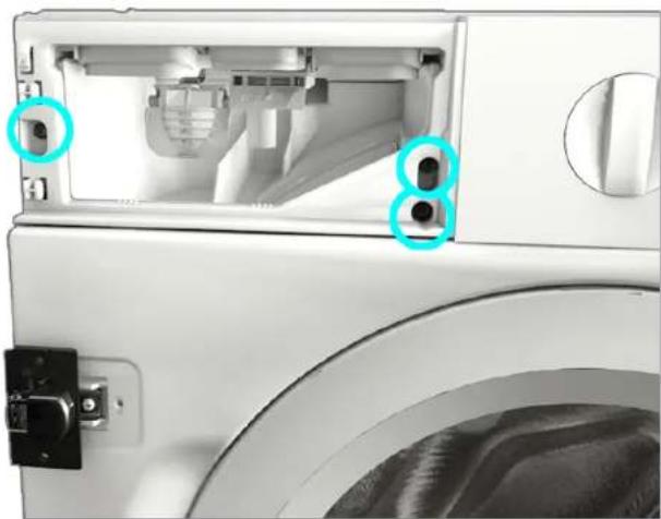
- Remove the screws. 3. 1. Release the fastening elements (1, 2).
2.

WARNING!

Repair

CAUTION

Repair

Repair
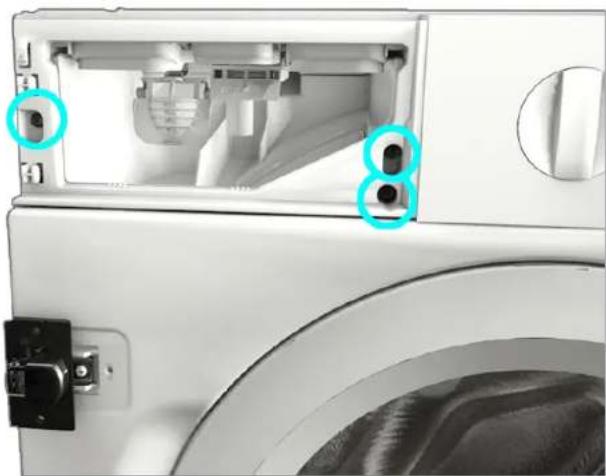
- Remove the screws. 3. 1. Release the fastening elements (1, 2).
- Remove the plate.
3.1.2 Installing the plate
▶ Install in reverse order.

Repair
3.2.2 Installing the detergent drawer
▶ Install in reverse order.

Repair
- Remove the detergent drawer handle.
3.3.2 Installing the detergent drawer handle
▶ Install in reverse order.

Repair
3.4 Replacing the door
CAUTION
- Remove the door upwards.
- Remove the door hinge.
3.6.2 Installing the door hinge
▶ Install in reverse order.

Repair
3.7 Replacing the door seal


Sharp edges on the housing!
Cuts
Wear protective gloves.


Danger of parts falling due to loose screws!
2.

CAUTION!
Risk of damage to the surface!
- Remove the door seal.
- Remove the door lock.

Repair
3.8.2 Installing the door lock

Fig. 1: Lower group cover
Requirement:

Repair
- Unscrew the screw (1).
- Press the retaining point and remove downwards (2).
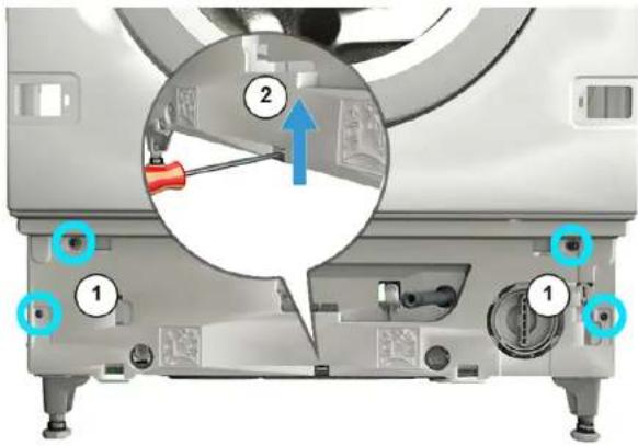
- Push the lower group cover and remove it towards the front.
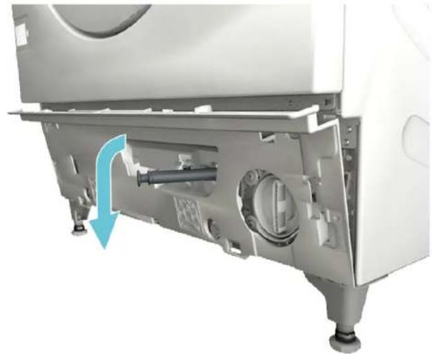
- Pull the hose out of the cover.

CAUTION
Repair
- Remove the front panel.

Repair
2.

WARNING!

Repair
2.

CAUTION

Repair

Repair
- Remove the control panel.
3.1.2 Mounting the control panel
- Remove the door upwards.
- Remove the door hinge.
NOTE!
Risk of damage to the surface!
- Remove the front panel.
- Disconnect all hose connections.
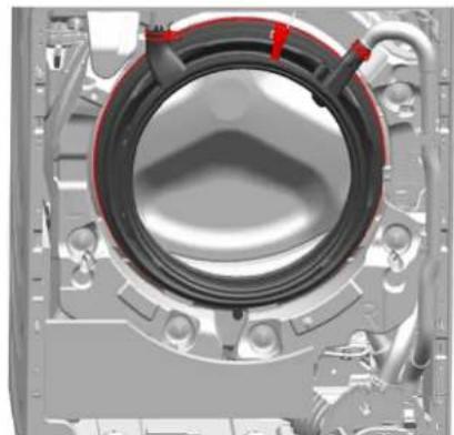
- Remove the door gasket.
- Remove the door lock.

Repair
▶ Make sure to secure appliances against slipping.


Fig. 1: Group cover at the bottom
Presetting:

Repair
2.




Repair
- Remove the front panel.
3.11.2 Mounting the front panel

Repair
3.2.2 Mounting the detergent drawer
3.5.2 Mounting the door components
2.

CAUTION!

Repair
2.

⚠️ CAUTION
Repair hints - Washing machine
i Concerning this document.... 103
1.1 Important information.... 103
1.1.1 Purpose.... 103
1.2 Explanation of symbols 103
1.2.1 Danger levels.... 103
1.2.2 Hazard symbols 103
1.2.3 Structure of the warnings.... 104
1.2.4 General symbols.... 104
Repair 106
3.1 Replacing fascia panel.... 106
3.1.1 Removing fascia panel 106
3.1.2 Installing fascia panel 107
3.2 Replacing detergent drawer 108
3.2.1 Removing detergent drawer.... 108
3.2.2 Installing detergent drawer.... 108
3.3 Replacing detergent drawer handle 109
3.3.1 Removing detergent drawer handle.... 109
3.3.2 Installing detergent drawer handle.... 109
3.9.1 Removing drum light.... 117
3.9.2 Installing drum light.... 117
3.10 Replacing bottom cover.... 118
3.10.1 Removing bottom cover 118
3.10.2 Installing the cover.... 119
3.11 Replacing front panel 120
3.11.1 Removing front panel.... 120
3.11.2 Installing front panel.... 121
i Concerning this document
1.1.1 Purpose
These repair hints support consumers to repair appliances by themselves according to the applicable eco-design regulation (as of 03/2021).
They contain information on how to exchange defined spare parts, including warnings and risks.
In case of questions, please contact our customer service. We will only be liable for damages if the repair hints have been followed properly.
1.2 Explanation of symbols
1.2.1 Danger levels
The warning levels consist of a symbol and a signal word. The signal word indicates the severity of the danger.
| Warning level Meaning | |
| Danger | Non-observance of the warning message will result in death or serious injuries. |
| Warning | Non-observance of the warning message could result in death or serious injuries. |
| Caution | Non-observance of the warning message could result in minor injuries. |
| Notice | Non-observance of the warning message could result in damage to property. |
Table 1: Danger levels
1.2.2 Hazard symbols
Hazard symbols are symbolic representations that give an indication of the kind of danger.
The following hazard symbols are used in this document:
| Hazard symbol Meaning | |
 | | General warning message |
 | | Danger from electrical voltage |
 | | Risk of explosion |
 | | Danger of cuts |
 | | Danger of crushing |
i Concerning this document
| Hazard symbol Meaning | |
 | | Danger from hot surfaces |
 | | Danger from strong magnetic field |
 | | Danger from non-ionizing radiation |
Table 2: Hazard symbols
1.2.3 Structure of the warnings
Warnings in this document have a standardized appearance and a standardized structure.

Type and source of danger!
Possible consequences of ignoring the danger / warning.
▶ Measures and prohibitions for preventing the danger.
The following example shows a warning that warns against electric shock due to live parts. The measure for avoiding the danger is mentioned.

Risk of electric shock due to live parts!
Death by electrocution
- Disconnect appliances from electrical supply at least 60 seconds before starting repairs.
1.2.4 General symbols
The following general symbols are used in this document:
| Gen. symbol Meaning | |
| Identification of a special tip (text and/or graphic) |
| Identification of a simple tip (only text) |
| Identification of a link to a video tutorial |
| Gen. symbol Meaning | |
| Identification of required tools |
| Identification of required preconditions |
| Identification of a condition (if ..., then ...) |
| Identification of a result |
| StartIdentification of a key or button | |
| [00123456] Identification of a material number |
| StatusIdentification of displayed text / window(in the appliance's display) |
Table 3: General symbols

| Designation Details Images | |
| Auxiliary tool[15000155] | Tool for loosening out of plastic parts | 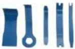 |
| Screwdriver Torx T20 with bore hole [00340764] | 100 mm, for screws with safety pin |  |
| Torque spanner [15000441] | Torque spanner 20 - 100 Nm | |
| Slot screwdriver [00340854] | Blade 3.5 mm x 0.6 mm x 100 mm, Protective Insulation 1000 V AC |  |
| Slot screwdriver [00340855] | Blade 5.5 mm x 1.0 mm x 125 mm, Protective Insulation 1000 V AC |  |
| Needle-nose pliers, angled pattern [00341269] | Length 200 mm | 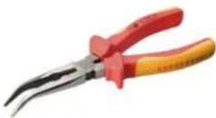 |
| Side-cutting pliers [00342182] | Length: 200 mm | 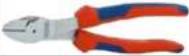 |
| Designation Details Images | |
| Combination wrench[00340811] | Wrench size 10°mm, M6 |  |
| Combination wrench[00340814] | Wrench size 13°mm, M8 |  |
| Combination wrench[00340817] | Wrench size 17 mm, M10 |  |
| Combination wrench[15000459] | Wrench size 16°mm, M10 |  |

Repair
3.1 Replacing fascia panel


Sharp housing edges!
Cut injuries
▶ Wear protective gloves.


Slipping of tilted appliances!
Bone fractures / crush injuries
- Secure appliances against slipping.


Risk of falling parts due to released screws!
Injury because of falling parts.
▶ Secure component from falling down.


Risk of falling parts due to released screws!
Damage to other parts of the appliance or at customer's home, e.g., bottom.
▶ Secure component from falling down.
Prerequisite:
√ Appliance is disconnected from power supply. √ Appliance is disconnected from water supply. √ Appliance is freely accessible. Detergent drawer has been removed. → Page 108
3.1.1 Removing fascia panel
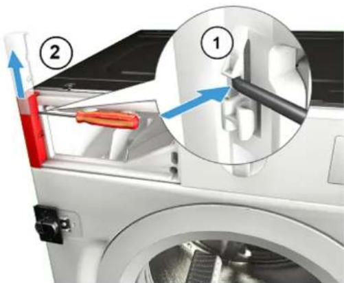
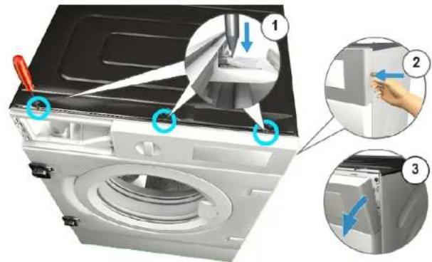
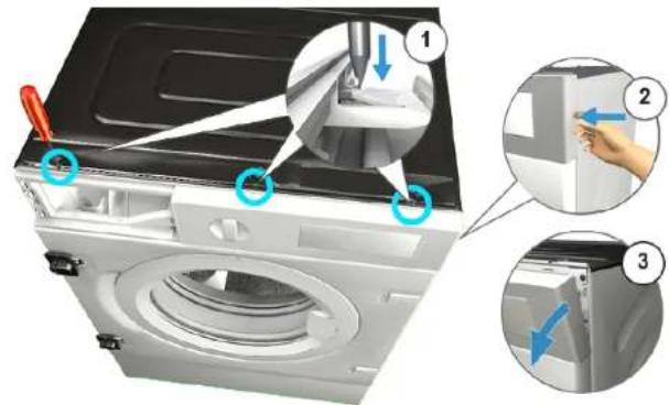
- Release catch element (1).
- Remove cover (2).

Repair
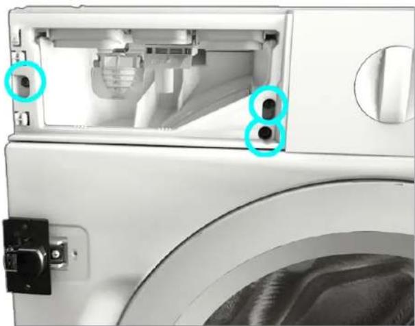
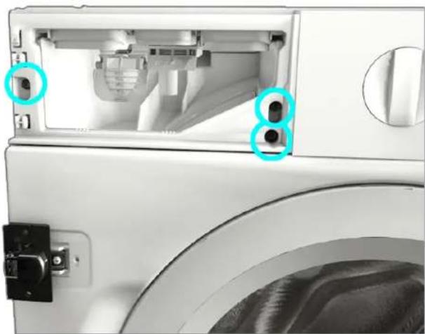
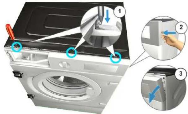
- Remove screws. 3. 1. Release catch elements (1, 2).
- Pull fascia panel to the front (3).
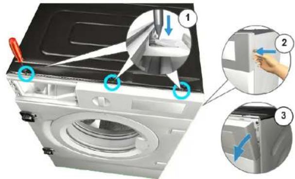
- Remove fascia panel.
3.1.2 Installing fascia panel
Install in reverse order.
Repair
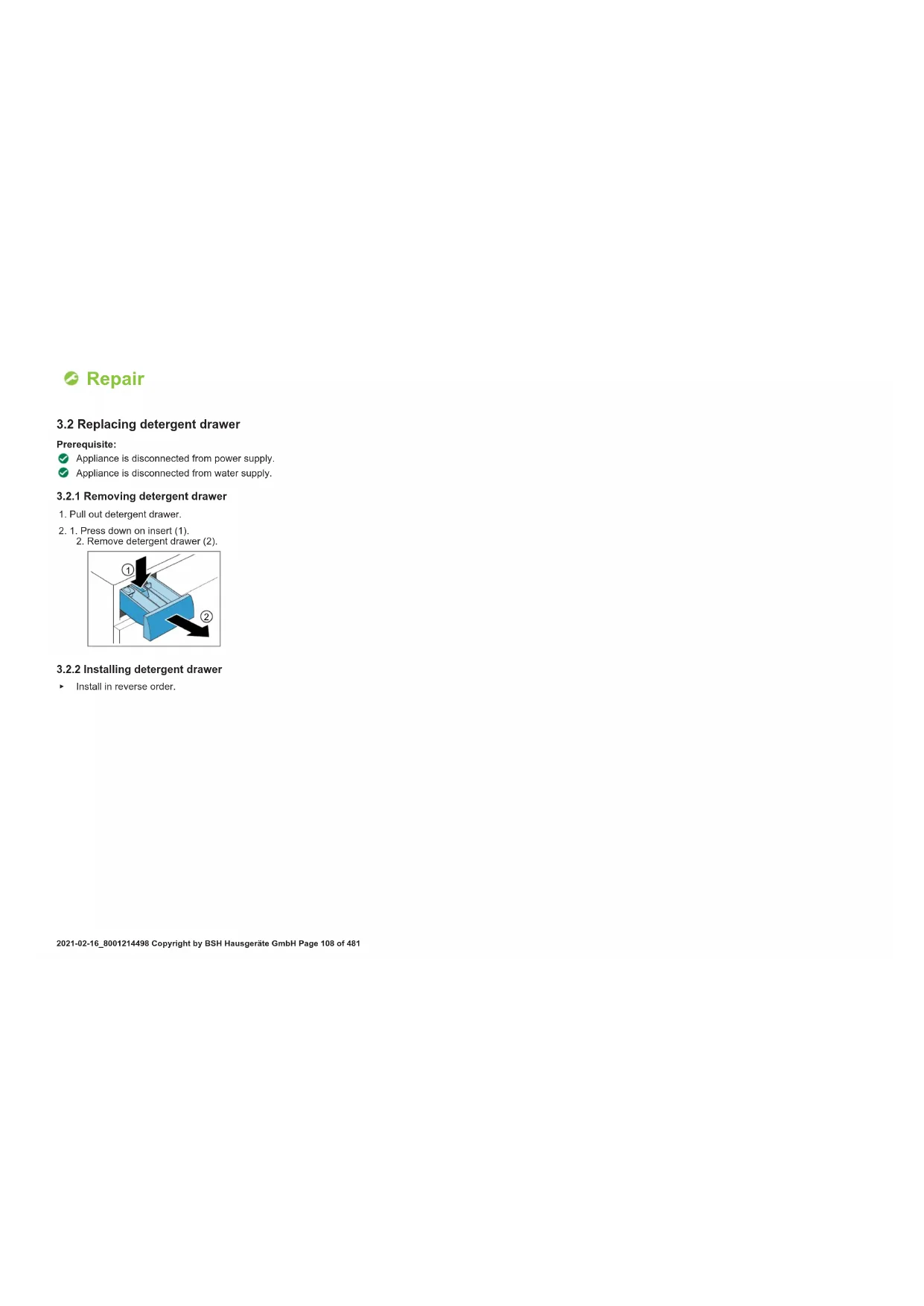
3.2 Replacing detergent drawer
Prerequisite:
Appliance is disconnected from power supply. Appliance is disconnected from water supply.
3.2.1 Removing detergent drawer
- Pull out detergent drawer. 2.1. Press down on insert (1).
- Remove detergent drawer (2).
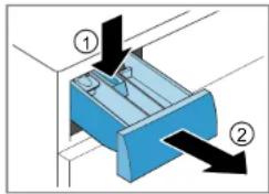
3.2.2 Installing detergent drawer
Install in reverse order.

Repair
3.3 Replacing detergent drawer handle
Prerequisite:
√ Appliance is disconnected from power supply. √ Appliance is disconnected from water supply. √ Detergent drawer has been removed.→ Page 108
3.3.1 Removing detergent drawer handle
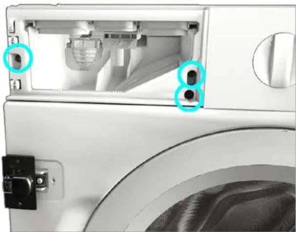
- Release catch elements.
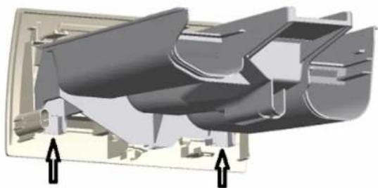
- Remove detergent drawer handle.
3.3.2 Installing detergent drawer handle
Install in reverse order.

Repair
3.4 Replacing door

Open hinge area
Finger crushing / entrapment
Do not reach into the hinge area.
▶ Wear protective gloves.
Prerequisite:
√ Appliance is disconnected from power supply. √ Appliance is disconnected from water supply. √ Door is opened. √ Furniture panel has been removed.
3.4.1 Removing door
1.
Notice
Risk of falling parts due to released screws!
Damage to other parts of the appliance or at customers home e.g. bottom.
▶ Secure component from falling down.

Risk of falling parts due to released screws!
Injury because of falling parts
- Secure component from falling down.
Remove screws (1).
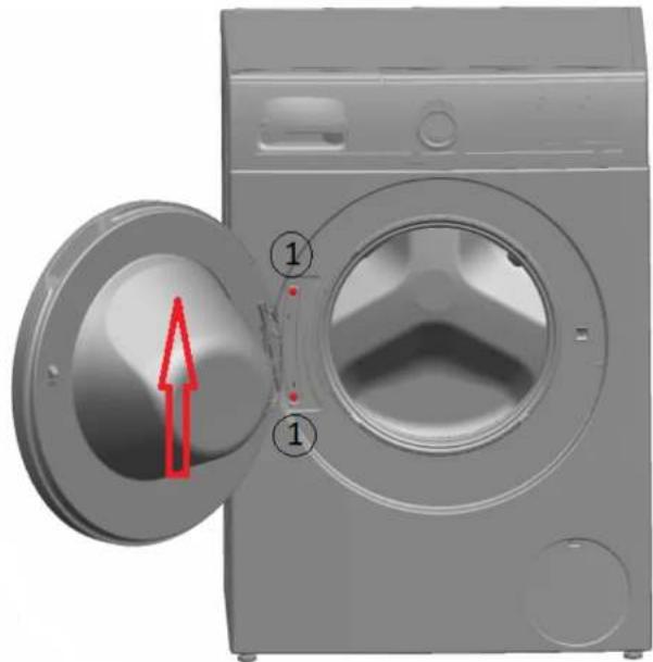
- Remove door upwards.
▶ Install in reverse order.

Repair
3.5 Replacing door components

Open hinge area
Finger crushing / entrapment
▶ Do not reach into the hinge area.
▶ Wear protective gloves.
Prerequisite:
√ Appliance is disconnected from power supply. √ Appliance is disconnected from water supply. √ Furniture panel has been removed. √ Door has been removed.→ Page 110
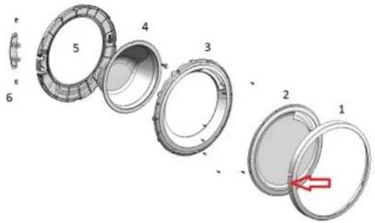
3.5.1 Removing door components
▶ Disassemble door from outside to inside.
3.5.2 Installing door components
▶ Install in reverse order.

Repair
Finger crushing / entrapment
▶ Do not reach into the hinge area.
Wear protective gloves.
Prerequisite:
Appliance is disconnected from power supply. Appliance is disconnected from water supply.
- Release two screws.
- Remove door.
- Disassemble door from outside to inside.
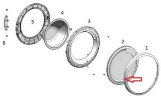
- Remove door hinge.
Install in reverse order.

Repair
3.7 Replacing door seal


Sharp housing edges!
Cut injuries
Wear protective gloves.


Risk of falling parts due to released screws!
Injury because of falling parts.
- Secure component from falling down.

Risk of falling parts due to released screws!
Damage to other parts of the appliance or at customer's home, e.g., bottom.
bottom.
- Secure component from falling down.
Prerequisite:
√ Appliance is disconnected from power supply. √ Appliance is disconnected from water supply. √ Appliance is freely accessible. √ Detergent drawer has been removed. → Page 108 √ Fascia panel has been removed. √ Door has been removed. → Page 110 √ Bottom cover has been removed. → Page 118
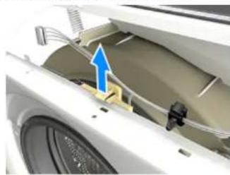
- Loosen the retainer on the drum light.

Notice
Risk of damaged surface!
Surface of appliance can be scratched by using wrong tools.
▶ Only use plastic tools to replace the tension ring.
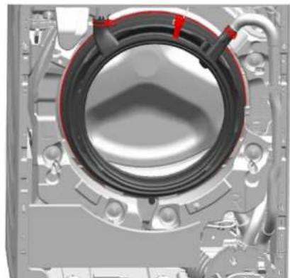
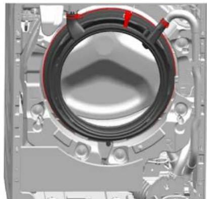
Remove tension ring from gasket with a plastic tool.
- Release door seal from front panel.
- Release cable connector from door lock.

Repair
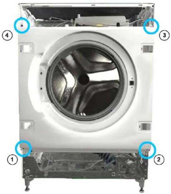
- Loosen the screws in the indicated order.
- Remove front panel.
- Disconnect all hose connections.
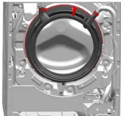
- Remove door seal.
Install in reverse order.

Repair
3.8 Replacing door lock
As a manufacturer, we are obliged to provide consumers with the spare part door lock including repair instructions in accordance with Regulation (EU) 2019/2023. However, we would like to point out that after replacing a door lock, an electrotechnical safety test by a qualified electrician is required before the device is put into operation. This person must be verifiably qualified according to the country-specific laws, regulations and standards.

Risk of electric shock due to live parts!
Danger to life through electric shock in case of improper repair
Electric parts should be repaired by a qualified electricians.
After the repair have a safety test according VDE 0701 or country-specific regulations performed.

Sharp housing edges!
Cut injuries
▶ Wear protective gloves.

Slipping of tilted appliances!
Bone fractures / crush injuries
▶ Secure appliances against slipping.

Risk of falling parts due to released screws!
Injury because of falling parts.
- Secure component from falling down.

Risk of falling parts due to released screws!
Damage to other parts of the appliance or at customers home e.g. bottom.
- Secure component from falling down.
Prerequisite:
√ Appliance is disconnected from power supply. √ Appliance is disconnected from water supply.
√ Appliance is freely accessible. √ Furniture panel has been removed. √ Fascia panel has been removed. √ Door has been removed. → Page 110 √ Tension ring has been removed. √ Front panel has been removed. √ Door seal has been removed.
- Disconnect door lock plug.
- Release door lock.
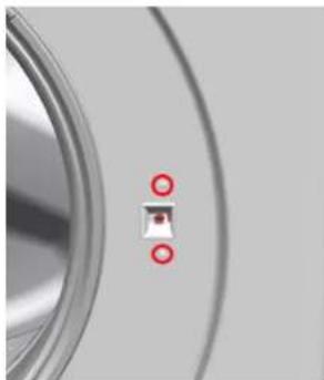
- Remove door lock.

Repair
Install in reverse order.

Repair
3.9 Replacing drum light


Sharp housing edges!
Cut injuries
Wear protective gloves.


Slipping of tilted appliances!
Bone fractures / crush injuries
Secure appliances against slipping.


Risk of falling parts due to released screws!
Injury because of falling parts.
- Secure component from falling down.


Risk of falling parts due to released screws!
Damage to other parts of the appliance or at customer's home, e.g., bottom.
- Secure component from falling down.
Prerequisite:
√ Appliance is disconnected from power supply. √ Appliance is disconnected from water supply. √ Appliance is freely accessible. √ Detergent drawer has been removed. → Page 108 √ Fascia panel has been removed.
3.9.1 Removing drum light
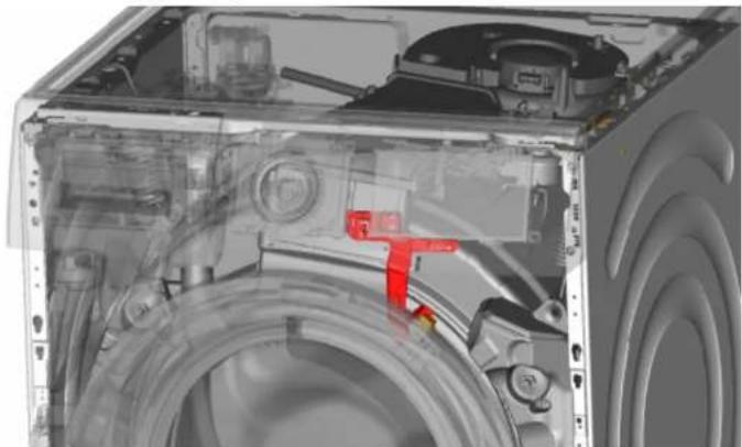
- Pull drum light holder out of appliance.
- Disconnect electrical connections.
- Remove drum light from drum light holder.
3.9.2 Installing drum light
▶ Install in reverse order.

Repair
3.10 Replacing bottom cover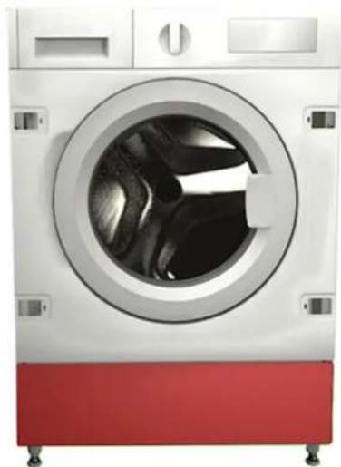
Fig. 1: Bottom group cover
Prerequisite:
√ Appliance is disconnected from power supply. √ Appliance is disconnected from water supply. √ Furniture panel has been removed.
3.10.1 Removing bottom cover
Prerequisite:
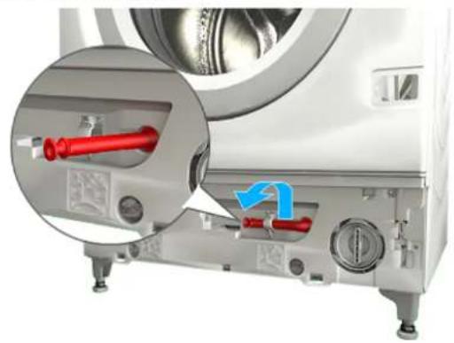
√ Appliance is disconnected from power supply. √ Appliance is disconnected from water supply. 1. Remove bottom cover.
- Detach hose from the holder.

Repair
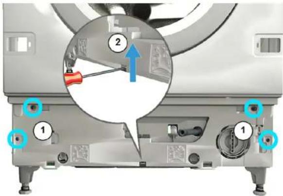
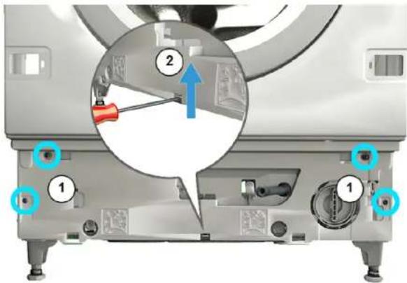
- Unscrew the screw (1).
- Press retaining point and remove downwards (2).
- Pull bottom group cover and remove forwards.
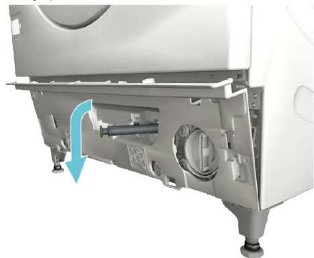
- Pull hose out of the cover.
3.10.2 Installing the cover
▶ Install in reverse order.

Repair
3.11 Replacing front panel

Prerequisite:
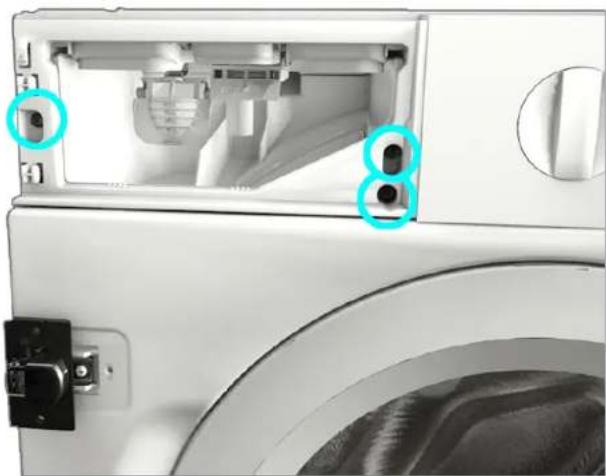
√ Appliance is disconnected from power supply. √ Appliance is disconnected from water supply. √ Appliance is freely accessible. √ Detergent drawer has been removed. → Page 108 √ Furniture panel has been removed. √ Door has been removed. → Page 110 √ Door seal has been removed.
3.11.1 Removing front panel
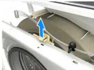
- Loosen the retainer on the drum light.

Caution
Risk of falling parts due to released screws!
Injury because of falling parts.
- Secure component from falling down.

Notice
Risk of falling parts due to released screws!
Damage to other parts of the appliance or at customer's home e.g. bottom.
▶ Secure component from falling down.
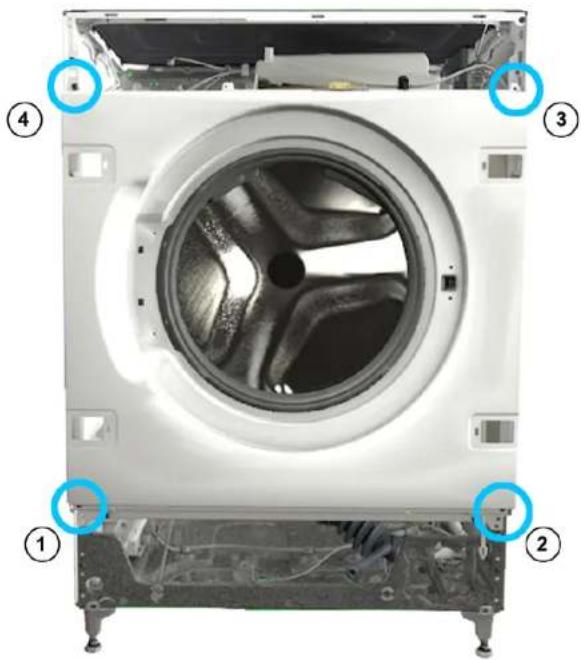
Loosen the screws in the indicated order.

Repair
- Remove front panel.
3.11.2 Installing front panel
▶ Install in reverse order.

Repair
3.2.2 Installing the detergent drawer
▶ Install in reverse order.
Repair
3.5.2 Installing door parts
▶ Install in reverse order.

Repair
2.

WARNING!
- Remove the door lock.

Repair
Figure 1: Bottom cover
Requirement:

Repair
2.

CAUTION!
Repair
- Remove the front panel.
3.11.2 Installing the front panel
▶ Install in reverse order.
Repair
- Remove the screws. 3. 1. Release the locking parts (1, 2).
3.2.2 Installing the washing machine door seal
2.

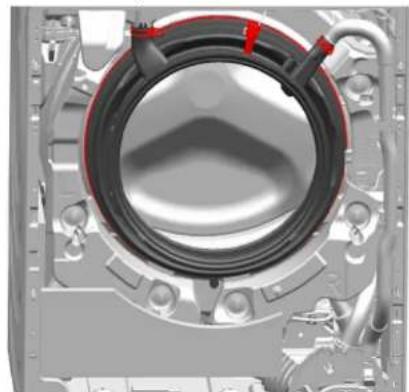
- Remove the door seal.

Repair
2.

NOTE
Repair
- Remove the front panel.
3.11.2 Installing the front panel

Repair
2.

CAUTION
Risk of superficial damage!
- Remove the door seal.
- Remove the door lock.

Repair

Repair


CAUTION

Repair

Repair
2.

WARNING

Repair

CAUTION

Repair
©

Repair
2.

CAUTION!

Repair
2.


Repair

Repair
2.

WARNING!

Repair

CAUTION

Repair
Repair
2.
WARNING!
Repair
2.

WARNING
Repair

Repairs
- Remove the door hinge.
2.

WARNING!
- Remove the front panel.
- Disconnect all pipe connections.
- Remove the door lock.

Repairs

Repairs
2.


BE CAREFUL
Repairs

Repairs
- Remove the headband.
2.
ATTENTION!
Fig. 1: Lower group cover
Requirement.

Repair

WARNING
Danger of parts falling when loosening screws!

Repair
Repair
- Remove the screws. 3. 1. Loosen the locking elements (1, 2).
- Pull the instrument panel towards the front (3).
- Remove the instrument panel.
Danger of crushing/pinching fingers
2.

OBS!
Careful for damage to the surface!
- Remove the front panel.
- Disconnect all hose connections.
- Remove the door lock.

Repair
Figure 1: Lower group cover
Prerequisite:
Repair

CAUTION
Repair
- Remove the front panel.

Repairs
2.

WARNING!

Repairs
2.

⚠️ IMPORTANT
Repairs

Repair
- Remove the screws. 3. 1. Release the snap-in elements (1, 2).
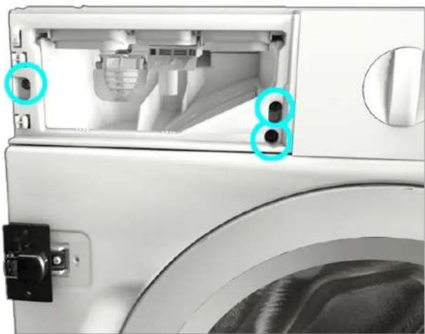
- Pull the control panel forward (3).
- Remove the control panel.
3.1.2 Installing the control panel
3.2.2 Installing the detergent drawer
2.

CAUTION!
Fig. 1: Lower assembly cover
Prerequisite:

Repair

CAUTION

Repair
- Remove the front panel.
3.11.2 Installing the front panel

Repair
3.5.2 Assembling the door components
2.


Repair
2.

WARNING

Repair
- Remove the trim panel.
3.1.2 Installing the trim panel
- Open the door upwards.
3.4.2 Door installation
2.
CAUTION!
Risk of surface damage!
- Remove the door lock.

Repair
- Pull out the drum light holder of the appliance.
- Disconnect the electrical connections.
- Remove the drum light from the drum light holder.

Repair
- Unscrew the screw (1).
- Press on the catch point and remove it downwards (2).
- Pull the hose out of the cover.
3.10.2 Installing the cover
2.

WARNING

Repair

Repair
- Remove the screws. 3. 1. Release the retaining elements (1, 2).
- Remove the detergent drawer handle.
- Remove the door in an upward direction.
2.
CAUTION!
- Remove the door seal.
- Remove the door lock.

Repair
- Pull the drum light holder out of the appliance.
- Disconnect the electrical connectors.
- Remove the drum light from the drum light holder.
Repair
2.

CAUTION
Repair

Repair
3.2.2 Mounting the detergent compartment
▶ Mount in reverse order.

Repair
3.3 Replacing the detergent compartment handle
Requirement:
2.

ATTENTION

Repair


CAUTION
Repair

Repair
- Pull the control panel towards the front (3).
- Remove the control panel.
3.1.2 Mounting the control panel
3.5.2 Mounting the door components

NOTE!
- Remove the front panel.
- Disconnect all hose connections.
- Remove the door lock.

Repair

Repair
- Pull the hose out of the housing.
3.10.2 Mounting the housing
2.

CAUTION

Repair
- Remove the front panel.
3.11.2 Mounting the front panel

Repair



Repair

CAUTION

Repair
- Remove the front panel.