Testavit Schuki 2K - Measuring equipment Testboy - Free user manual and instructions
Find the device manual for free Testavit Schuki 2K Testboy in PDF.
| Product type | Socket and RCD tester |
| Brand | Testboy |
| Model | Testavit Schuki 2K |
| Dimensions | 100 x 50 x 75 mm |
| Weight | 100 g |
| Power supply | 230 V, 50 Hz (via mains socket) |
| Display | Neon lamps |
| Main functions | Socket wiring check, residual current circuit breaker test |
| Adjustable rated fault current | 10, 30, 100, 300, 500 mA |
| RCD test duration | 200 ms |
| Permissible ambient temperature | -10 °C to +30 °C |
| Maximum connection time | Unlimited |
| Insulation | Class II protection |
| Contact electrode | Leakage current < 10 μA |
| Maintenance and cleaning | Clean with a dry cloth. Do not use solvents. |
| Safety | Do not use on installations under dangerous voltage. Follow the instructions in the manual. |
| Spare parts and repairability | No spare parts available. In case of defect, contact customer service. |
| General information | Device intended only for applications described in the manual. Any other use is prohibited. |
Frequently Asked Questions - Testavit Schuki 2K Testboy
User questions about Testavit Schuki 2K Testboy
0 question about this device. Answer the ones you know or ask your own.
Ask a new question about this device
Download the instructions for your Measuring equipment in PDF format for free! Find your manual Testavit Schuki 2K - Testboy and take your electronic device back in hand. On this page are published all the documents necessary for the use of your device. Testavit Schuki 2K by Testboy.
USER MANUAL Testavit Schuki 2K Testboy
GB Operating instructions
F Mode d'emploi
FI fuse and socket outlet tester
text_image
L2 GL1 L1 PE N SCHUKI 2 T L3 FL1 Z30 V~ T Amptext_image
L2 G1 L1 G3 1 2mp L2 F1 T SCHUNI 2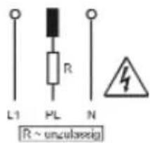
text_image
L1 PL R N [R ~ unculaseig]The Schuki 2 is a test device for testing socket outlets, cable connections and circuits protected by earth-leakage circuit breakers (ELCB) in 230-V systems as well as older installations with classic 'protective multiple earthing'. Socket outlets and connecting cables are tested for correct wire connections.
The effectiveness of ELCB protected circuits is tested by calibrating the nominal fault current.
Device description
The Schuki 2 is plugged straight into the socket outlet to be tested in the installation. The touch electrode on the top of the housing functions according to the same principle as a phase tester.
Functions
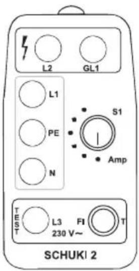
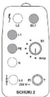
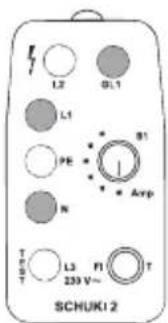
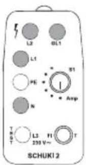
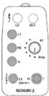
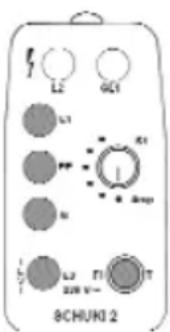
The Schuki 2 (figure 1) is divided into three areas:
■ The red warning area indicates the function of the protective earth.
■ The yellow testing area indicates the wiring connections.
■ The green area is responsible for the earth-leakage circuit breaker (ELCB).
The status of the protective circuit of the socket being tested is indicated by a combination of glowing and non-glowing lamps.
The lamps and their meanings
In the yellow area:
L1 Phase conductor
PE Protective earth
N Neutral conductor
In the red area:
L2 Protective earth
GL1 Touch electrode
In the green area: L3 ELCB protected circuit
text_image
L2 GL1 L1 PE N S1 Amp TEST L3 FI T 230 V~ SCHUKI 2Figure 1: Schuki 2
Control elements
Two elements available for testing the ELCB circuitry.
■ (S1) Rotary switch to adjust the nominal fault current
■ (T) A button to trigger the nominal fault current
The touch electrode tests the phase conductor according to the principle of a phase tester.
Symbols used in this documentation
To provide a better overview, images are used to enhance the descriptions of faults. For this purpose, the following symbols are used:
■ Symbol not shaded:
The lamp is not glowing or the button has not been pressed
■ Symbol shaded:
The lamp lights up or the button has been pressed
■ Plug symbol for test results:
The recognised circuitry is portrayed.
■ Danger symbols:
The recognised circuit is a danger to life.

Checking socket outlets and connecting wires
The test is the same for both socket outlets and connecting wires. For this reason, only socket outlets are mentioned in this documentation.
The device is very easy to operate: turn the switch S1 to OFF, and plug the device into the socket outlet to be tested. You should ensure that the phase conductor connects to the left-hand pin (viewed when device is inserted and faceplate visible).
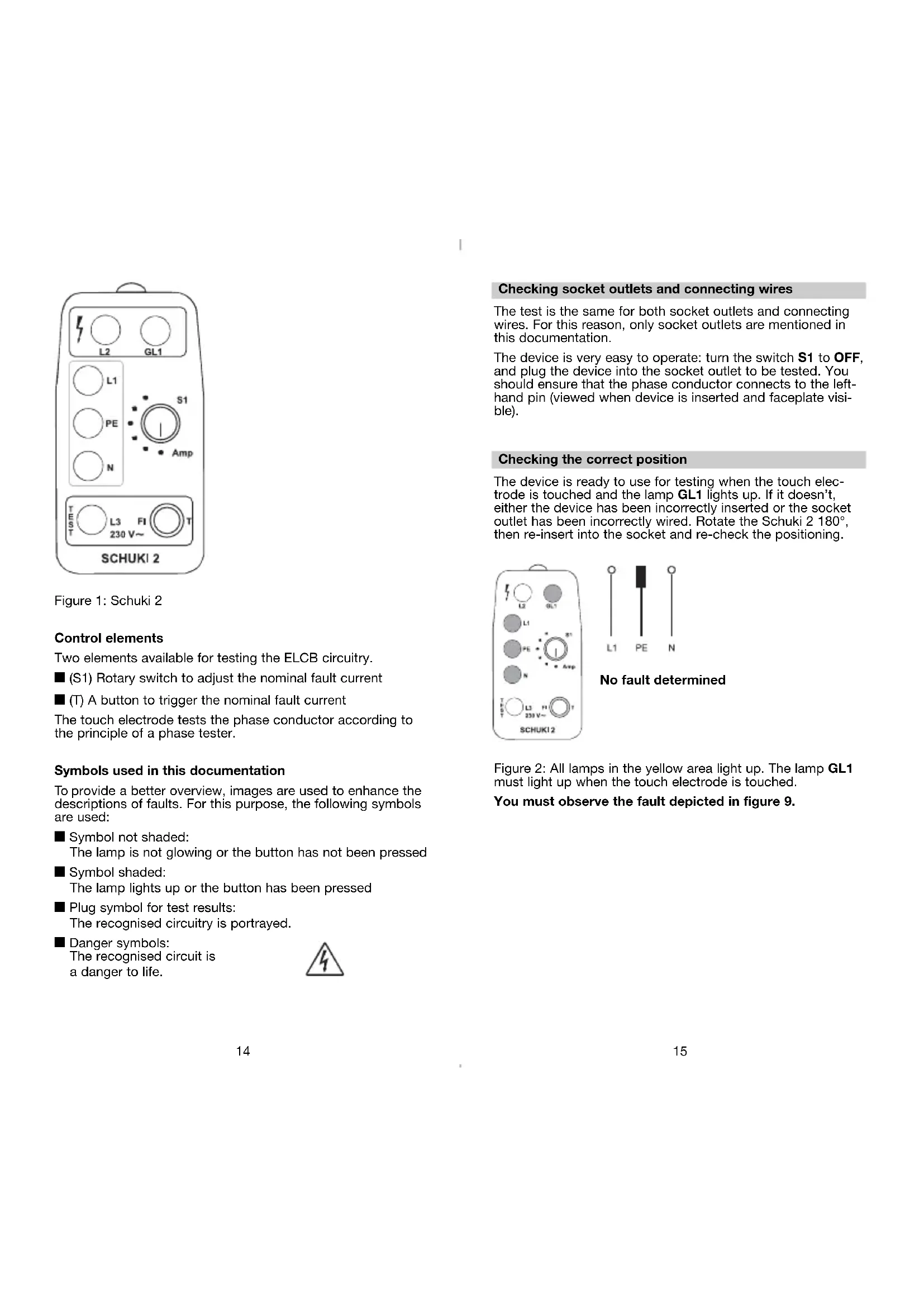
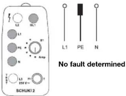
Checking the correct position
The device is ready to use for testing when the touch electrode is touched and the lamp GL1 lights up. If it doesn't, either the device has been incorrectly inserted or the socket outlet has been incorrectly wired. Rotate the Schuki 2 180°, then re-insert into the socket and re-check the positioning.
text_image
L2 OL1 L1 PE S1 N Avg T L3 230 V~ T SCHUKI 2 L1 PE N No fault determinedFigure 2: All lamps in the yellow area light up. The lamp GL1 must light up when the touch electrode is touched.
You must observe the fault depicted in figure 9.
Fault indication
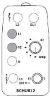
No current flowing
None of the lamps light up. Touch the touch electrode as well. Should none of the lamps light up, the phase conductor is not connected.
If one of the lamps in the yellow area glows, then the phase conductor is connected to the respective connection.
text_image
L2 GL1 L1 PE N SCHUKI 2 T C R T L3 239 V~ PI Amp 31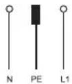
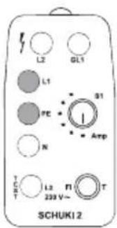
Device plugged incorrectly
Figure 3: The lamps N, L1 and L2 light up. When the touch electrode is touched, the lamp GL1 does not light up.
The phase conductor is not contacting the left-hand pin of the test device (viewed when device is inserted and faceplate visible); it cannot be tested. Rotate the Schuki 2 180° and re-insert.
text_image
L2 GL1 L1 PE 51 N Amp T L3 n 238 V~ SCHUKI 2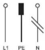
No neutral conductor
Figure 4: The lamps L1 and PE light up. GL1 lights up when the touch electrode is touched.
You must observe the fault depicted in figure 5.
text_image
L2 GL1 L1 PE N Amp L3 FI T 230 V~ SCHUKI 2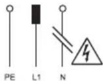
No neutral conductor,
Phase and protective earth have been
reversed.
Figure 5: The lamps L1 and PE light up. Touching the touch electrode has no effect.
The phase conductor is connected to the earthing contact!
text_image
L2 GL1 L1 B1 PE N Amp T L3 FI 239 V~ T SCHUKI 2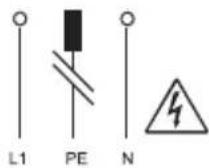
No protective earth
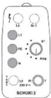
Figure 6: The lamps L1 and N light up. GL1 lights up when the touch electrode is touched.
text_image
L2 GL1 L1 S1 PE I N Amp T L3 PI T 230 V~ SCHUKI 2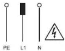
Phase and PE conductors have been reversed
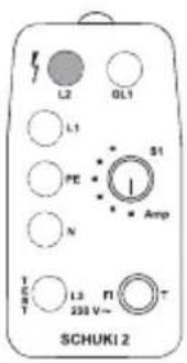
Figure 7: Lamp L2 only lights up. Touching the touch electrode has no effect.
This fault configuration is indicated when the testing device has been incorrectly inserted.
The phase conductor is connected to the earthing contact!
text_image
L2 OL1 L1 S1 PE N Amp T H L3 F1 239 V~ T S T SCHUKI 2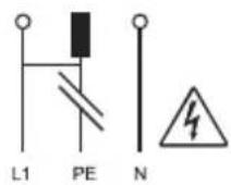
No protective earth, phase conductor connected to earthing contact
Figure 8: The lamps N, L1 and L2 light up. GL1 lights up when the touch electrode is touched.
This is a typical fault with older installations with classic 'protective multiple earthing', if the phase and protective earth conductors have been reversed.
The phase conductor is connected to the earthing contact!
text_image
L3 GL1 L1 PE N S1 - Amp T G T L3 HI 239 V~ T SCHUKI 2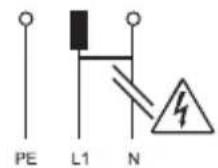
Open neutral, phase conductor connected to earthing contact
Figure 9: The lamps L1, PE and N light up. Touching the touch electrode has no effect.
This is a typical fault in older installations with classic 'protective multiple earthing', if the phase and protective earth conductors have been reversed.
The phase conductor is connected to the earthing contact!
Testing the ELCB protected circuit
Insert the testing device into a socket outlet and test the circuitry. If no fault is indicated, you can begin testing the ELCB function.
Using the switch S1, adjust the nominal fault current to the required value; press the button T. The nominal fault current flows for 200 ms.
Note:
This test can also be carried out in systems not fitted with an ELCB.
■ It is permitted to press the button T once every 10 seconds only.
text_image
L2 GL1 L1 S1 PE - N Amp T E S L3 H 230 V~ SCHUKI 2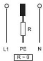
No fault determined
Figure 10: All lamps in the yellow area light up. In addition, the lamp L3 lights up when the button T is pressed. The lamps go out when the ELCB is tripped.
Please refer to the first fault indication FI, if the ELCB is not tripped.
text_image
L2 6D1 L1 81 1 800V L2 T1 T 8CHUKI 2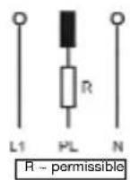
Earth wire resistance is still permissible
Figure 11: All lamps in the yellow area light up.
In addition, L3 lights up when the button T is pressed; simultaneously the PE lamp goes out.
The lamps go out when the ELCB is tripped.
The protective earth conductor has an increased but permissible resistance.
ELCB fault indication
Neutral and PE conductors reversed ELCB protection defective
The fault is indicated as portrayed in figure 10.
In this case the ELCB is not tripped, the lamps in the yellow area continue to glow.
text_image
L2 GCI L1 R1 1 Amp N L2 T1 T 200 V- 8CHUKI 2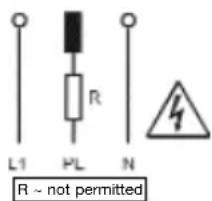
text_image
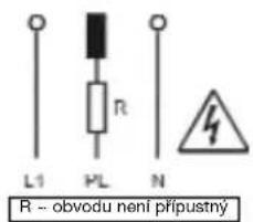
L1 PL R N R ~ not permittedProtective earth resistance too high
Figure 12: All lamps in the yellow area light up. In addition, L3 lights up when the button T is pressed. Simultaneously, the PE lamp goes out, and L2 flashes on for short period.
L3 goes out after 200 ms; the lamps in the yellow area continue to glow. The ELCB is not tripped.
The resistance of the PE conductor in unacceptably high. Life threatening voltages can build up at the earthing contact!
Technical data
| Operating voltage: 230 V, 50 Hz |
| Display: Glow lamps |
| Nominal fault current: 10-30-100-300-500 mA200 ms |
| Permissible ambient temperature: -10 °C ... +30 °C |
| Insertion time: Unrestricted |
| Insulation: Protection class 2 |
| Touch electrode: Leakage current < 10 μA |
| Dimensions: 100 x 50 x 75 mm |
| Weight: 100 g |
Fields of application
The tool is intended for use in applications as described in the operating instructions only.
Any other form of usage is not permitted and can lead to accidents or destruction of the device. Any misuse will result in the expiry of all guarantee and warranty claims on the part of the operator against the manufacturer.
F Mode d'emploi
text_image
L2 GCI L1 R R L2 F1 T 8CHUNI 2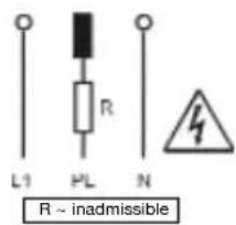
text_image
L1 PL R N R ~ inadmissibletext_image
L2 6D1 L1 B1 1 Bmp L2 T1 T 8CHUKI 2text_image
L2 GCI L1 G3 I Bmp L3 T1 T 8CHUNI 2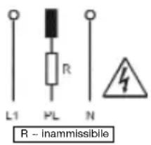
text_image
L1 PL R N R - inammissibiletext_image
L2 GL1 L1 PC N T S T L3 H 230 V- SCHUKI 2 Amptext_image
L1 PL R N R ~ inadmissiveltext_image
L2 GL1 L1 S1 PC N Amp T L3 FL T 233 V- SCHUKI 2text_image
L2 GCI L1 A1 1 Amp N L2 T1 T 8CHUKI 2text_image
L2 GCI L1 A1 I N BCHUNI 2 L2 T1 T 20W N-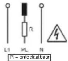
text_image
L2 GL1 L1 FE N S1 I Amp T P S T L3 F1 230 V~ T SCHUK12text_image
L2 GCI L1 A1 I Amp N L2 T1 T 8CHUKI 2 500 V-text_image
L2 GL1 L1 S1 PC N Amp T L3 FL T 233 V- SCHUKI 2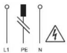
text_image
L2 6D1 L1 N R1 I Bmp L2 N T 8CHUNI 2