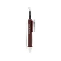
TB115 Bit - Measuring equipment Testboy - Free user manual and instructions
Find the device manual for free TB115 Bit Testboy in PDF.


| Brand | Testboy |
| Model | TB115 Bit |
| Product type | Non-contact voltage detector with bit holder |
| Voltage range | 12 - 1000 V AC |
| Power supply | 2 x 1.5 V AAA batteries (micro) |
| Protection rating | IP40 |
| Overvoltage category | CAT III 1000 V / CAT IV 600 V |
| Safety standard | IEC/EN 61010-1 (DIN VDE 0411) |
| Light indicator | White cap: red (>110 V AC), blue (flashlight active), purple (12-110 V AC detected) |
| Integrated flashlight | Yes, separate switch |
| Vibration notification | Yes, when voltage is detected |
| Magnetic bit holder | Yes, for screwdriver bits (small bits recommended) |
| Non-contact voltage detection | From 12 V AC with flashlight activated |
| Maintenance and cleaning | Clean with a dry cloth |
| Battery replacement | Open the compartment with a screwdriver, observe polarity |
| Intended use | Only for the applications described in the manual |
| Country of origin | Germany (Testboy, est. 1953) |
| Warranty | Subject to Testboy conditions (exclusion in case of non-compliance with the manual) |
| Included accessories | Not specified (bits not included) |
| Dimensions | Approx. 160 mm (length), standard diameter |
| Weight | Approx. 60 g (with batteries) |
Frequently Asked Questions - TB115 Bit Testboy
Note: Non-contact testing does not certify the absence of voltage.
User questions about TB115 Bit Testboy
0 question about this device. Answer the ones you know or ask your own.
Ask a new question about this device
Download the instructions for your Measuring equipment in PDF format for free! Find your manual TB115 Bit - Testboy and take your electronic device back in hand. On this page are published all the documents necessary for the use of your device. TB115 Bit by Testboy.
USER MANUAL TB115 Bit Testboy
Testboy® TB115 Bit
Version 1.4
de Testboy® TB115 Bit Bedienungsanleitung 3
en Testboy® TB115 Bit 9
Operating instructions
fr Testboy® TB115 Bit 16
Mode d'emploi
Testboy® TB115 Bit 23
Instrucciones de empleo
it Testboy® TB115 Bit 30
Istruzioni per l'uso
Testboy® TB115 Bit 37
Gebruiksaanwijzing
Testboy® TB115 Bit 44
Instrukcja obsługi
Testboy® TB115 Bit 51
Bruksanvisning
Sicherheitshinweise

WARNUNG
Batteriewechsel
An additional source of danger is posed my mechanical parts which can cause severe personal injury.
Objects can also be damaged (e.g., the instrument itself can be damaged).
WARNING
An electric shock can result in death or severe injury. It can also lead to proper damage and damage to this instrument.

WARNING
Never point the laser beam directly or indirectly (on reflective surfaces) toward eyes. Laser radiation can cause irreparable damage to the eyes. You must first deactivate the laser beam when measuring close to people.
General safety notes

WARNING
Unauthorized changes or modifications of the instrument are forbidden – such changes put the approval (CE) and safety of the instrument at risk. In order to operate the instrument safely, you must always observe the safety instructions, warnings and the information in the "Proper and Intended Use" Chapter.

WARNING
Please observe the following information before using the instrument:
Do not operate the instrument in the proximity of electrical welders, inducti heaters and other electromagnetic fields.
After an abrupt temperature fluctuation, the instrument should be allowed to adjust to the new temperature for about 30 minutes before using it. This help stabilize the IR sensor.
Do not expose the instrument to high temperatures for a long period of time. Avoid dusty and humid surroundings.
Measurement instruments and their accessories are not toys. Children should never be allowed access to them!
In industrial institutions, you must follow the accident prevention regulation electrical facilities and equipment, as established by your employer's liabilit insurance organization.

Please observe the following five safety rules:
1 Disconnect.
2 Ensure that the instrument cannot be turned back on again.
3 Ensure isolation from the main supply voltage (check that there is no voltage on both poles).
4 Earth and short-circuit.
5 Cover neighbouring parts that are under live electrical load.
Proper and intended use
This instrument is intended for use in applications described in the operation manual only. Any other usage is considered improper and non-approved us-age and can result in accidents or the destruction of the instrument. Any misuse will result in the expiry of all guarantee and warranty claims on the part of the operator against the manufacturer.

Remove the batteries during longer periods of inactivity in order to avoid damaging the instrument.

We assume no liability for damages to property or personal injury caused by improper handling or failure to observe safety instructions. Any warranty claim expires in such cases. An exclamation mark in a triangle indicates safety notices in the operating instructions. Read the instructions completely before beginning the initial commissioning. This instrument is CE approved and thus fulfils the required guidelines.
All rights reserved to alter specifications without prior notice
© 2020 Testboy GmbH, Germany.
Disclaimer and exclusion of liability

The warranty claim expires in cases of damages caused by failure to observe the instruction! We assume no liability for any resulting damage!
Testboy is not responsible for damage resulting from:
failure to observe the instructions,
changes in the product that have not been approved by Testboy,
the use of replacement parts that have not been approved or manufactured by Testboy,
the use of alcohol, drugs or medication.
Correctness of the operating instructions
These operating instructions have been created with due care and attention. No claim is made nor guarantee given that the data, illustrations and drawings are complete or correct. All rights are reserved in regards to changes, print failures and errors.
Disposal
For Testboy customers: Purchasing our product gives you the opportunity to return the instrument to collection points for waste electrical equipment at the end of its lifespan.
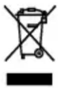
The WEEE directive regulates the return and recycling of electrical appliances. Manufacturers of electrical appliances are obliged to take back and recycle all electrical appliances free of charge. Electrical devices may then no longer be disposed of through conventional waste disposal channels. Electrical appliances must be recycled and disposed of separately. All equipment subject to this directive is marked with this logo.
Disposing of used batteries
As an end user, you are legally obliged (by the relevant laws concerning battery disposal) to return all used batteries. Disposal with normal household waste is prohibited!
Contaminant-laden batteries are labelled with the adjacent symbol which indicates the prohibition of disposal with normal household waste.
The abbreviations used for heavy metals are:
Cd = Cadmium, Hg = mercury, Pb = lead.
You can return your used batteries for no charge to collection points in your community or everywhere where batteries are sold!
Certificate of quality
All aspects of the activities carried out by Testboy GmbH relating to quality during the manufacturing process are monitored permanently within the framework of a Quality Management System. Furthermore, Testboy GmbH confirms that the testing equipment and instruments used during the calibration process are subject to a permanent inspection process.
Declaration of Conformity
The product conforms to the present directives. For more detailed information, go to www.testboy.de
Operation
Thank you for choosing a Testboy ® TB115 Bit.
Non-contact voltage tester from 12 V AC
| Integrated bit bracket
Non-contact voltage test
The Testboy ® TB115 Bit is capable of detecting wires carrying live voltages using its built-in circuits in its tip.
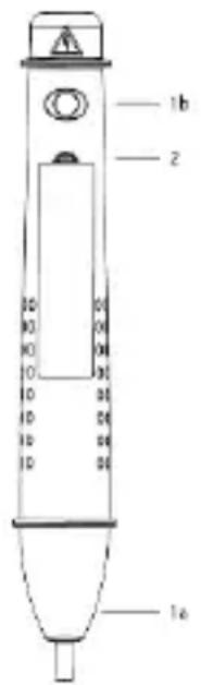
If a voltage of 110 V AC or more is detected, the white cap will glow red (1a) and the device vibrates. To detect voltages below 110 V AC, switch the flashlight on using the switch (1b). The white cap now illuminates blue (see figure point 1a). Now voltages from 12 V AC can be detected. If an AC voltage of 12 Volt AC or higher is detected, the white cap will illuminate purple (blue + red see figure, point 1a).
A flowing current is not required!

Check the voltage tester before use against a known voltage supply (e.g. a power socket) to ensure that it is working correctly.
Do not use the voltage tester if damaged!
When using the Tester, if tip does not glow, voltage could still be present. The Tester indicates active voltage in the presence of electrostatic fields of sufficient strength generated from the source (MAINS) voltage. If the field strength is low, the Tester may not provide indication of live voltages. Lack of an indication occurs if the Tester is unable to sense the presence of voltage which may be influenced by several factors including, but not limited to:
- Shielded wire/cables
- Thickness and type of insulation
- Distance from the voltage source
● Fully-isolated users that prevent an effective ground
● Receptacles in recessed sockets/ differences in socket design - Condition of the Tester and Batteries

WARNING
Use caution with voltages above 30 V ac as a shock hazard may exist.
FOR USE BY COMPETENT PERSONS
Anyone using this instrument should be knowledgeable and trained about the risks involved with measuring voltage, especially in an industrial setting, and the importance of taking safety precautions and of testing the instrument before and after using it to ensure that it is in good working condition.
The single-pole phase testing is not appropriate to determine whether a line is live or not. For this purpose, the double-pole voltage test is always required.
Definition of measurement categories.
Measurement category II:
Measurement category II is applicable to test and measuring circuits connected directly to utilization points (socket outlets and similar points) of the low-voltage mains installation. Typical short-circuit current is < 10 kA.
Measurement category III:
Measurement category III is applicable to test and measuring circuits connected to the distribution part of the building's low-voltage mains installation. Typical short-circuit current is < 50 kA.
Measurement category IV:
Measurement category IV is applicable to test and measuring circuits connected at the source of the building's low-voltage mains installation. Typical short-circuit current is >>50 kA.
Read the instruction before use. If the equipment is used in a manner not specified by the manufacturer, the protection provided by the equipment may be impaired.
All parts of the device and its accessories are not allowed to be changed or replaced, other than authorized by the manufacturer or his agent.
For cleaning the unit, use a dry cloth.
Bit bracket
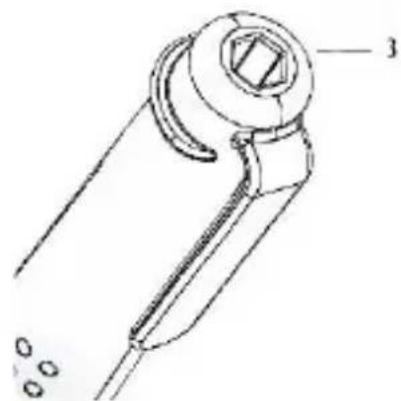
Insert the desired bit in the bracket designed for this purpose (see figure, point 3). An integrated magnet prevents the bit from falling out. In view of the technical design, we recommend that you only use small bits.
Changing the batteries
Insert a screwdriver in to the notch (2) and pry the battery compartment cover off. Make sure you insert the batteries the right way round!

Only commission instruments that are closed!

Do not dispose of batteries in normal household rubbish! Use an authorised local collection point!
Technical data
| Voltage range | 12 - 1000 V AC |
| Power supply | 2 x 1.5 V AAA Micro |
| Degree of protection | IP 40 |
| Overvoltage category | CAT III 1000 V / CAT IV 600 V |
| Testing standard | IEC/EN 61010-1 (DIN VDE 0411) |
Cd = cadmium, Hg = mercure, Pb = plomb.
Cambio de las pilas
Cd = cadmium, Hg = kwik, Pb = lood.
Batterij vervangen
Wymiana baterii
Cd = kadmium, Hg = kvicksilver, Pb = bly.
Byte av batterier




- TESTBOY® TB115 BIT
- SICHERHEITSHINWEISE
- WARNUNG
- BATTERIEWECHSEL
- WARNING
- GENERAL SAFETY NOTES
- PROPER AND INTENDED USE
- DISCLAIMER AND EXCLUSION OF LIABILITY
- CORRECTNESS OF THE OPERATING INSTRUCTIONS
- DISPOSAL
- DISPOSING OF USED BATTERIES
- CERTIFICATE OF QUALITY
- DECLARATION OF CONFORMITY
- OPERATION
- NON-CONTACT VOLTAGE TEST
- FOR USE BY COMPETENT PERSONS
- DEFINITION OF MEASUREMENT CATEGORIES
- MEASUREMENT CATEGORY II
- MEASUREMENT CATEGORY III
- MEASUREMENT CATEGORY IV
- BIT BRACKET
- CHANGING THE BATTERIES
- CAMBIO DE LAS PILAS
- BATTERIJ VERVANGEN
- WYMIANA BATERII
- BYTE AV BATTERIER
Brand : Testboy
Model : TB115 Bit
Category : Measuring equipment