D25500K - Hammer DEWALT - Free user manual and instructions
Find the device manual for free D25500K DEWALT in PDF.

| Product Type | Electropneumatic Hammer |
| Brand | DeWalt |
| Model | D25500K |
| Rated Voltage | 230 V |
| Power Input | 1,050 W |
| Impact Energy | 1‑9 J |
| Drilling Capacity Concrete (Drill) | 12‑40 mm |
| Drilling Capacity Concrete (Core Bit) | 40‑90 mm |
| Chisel Positions | 8 |
| Tool Holder | SDS Max® |
| Weight | 6.0 kg |
| Sound Pressure LpA | 92 dB(A) |
| Sound Power LwA | 103 dB(A) |
| Vibration Drilling Concrete (ah,HD) | 18.0 m/s² |
| Vibration Chiseling (ah,Cheq) | 14.5 m/s² |
| Soft Start Feature | Yes |
| Torque Limiter | Yes |
| Electronic Speed and Impact Control | Yes (5 positions) |
| Insulation | Double Insulation (Class II) |
| Accessory Type | SDS Max |
| Package Contents | Hammer, side handle, depth stop, lubricant tube, carry case, manual |
| Warranty | 1 year (with 1 year free maintenance contract) |
Frequently Asked Questions - D25500K DEWALT
User questions about D25500K DEWALT
0 question about this device. Answer the ones you know or ask your own.
Ask a new question about this device
Download the instructions for your Hammer in PDF format for free! Find your manual D25500K - DEWALT and take your electronic device back in hand. On this page are published all the documents necessary for the use of your device. D25500K by DEWALT.
USER MANUAL D25500K DEWALT
English (original instructions)
EAAnvika (eTARaPaaon aTIO npiWorotues oOyies) 117
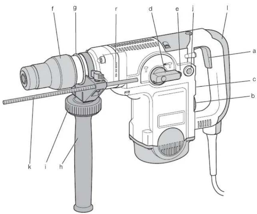
Figure 1
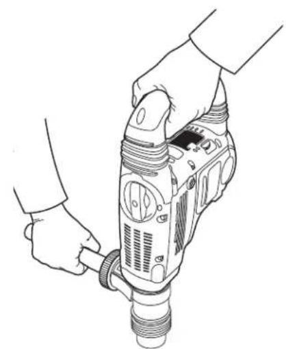
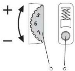
Figure 2
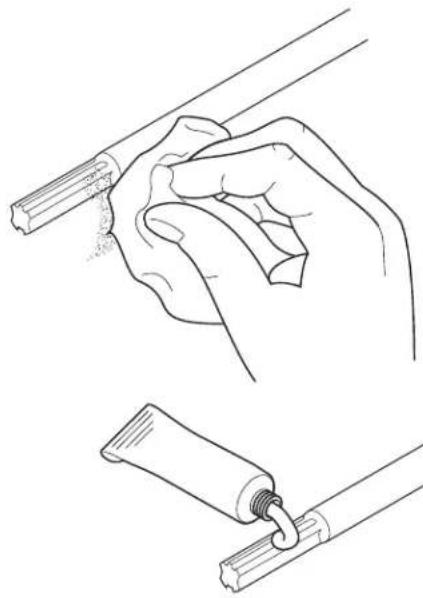
Figure 3
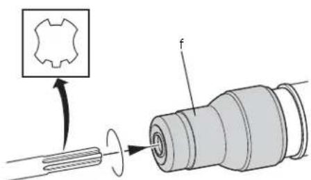
Figure 4
Figure 5
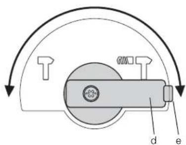
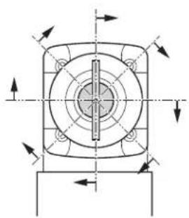
Figure 6 Figure 7
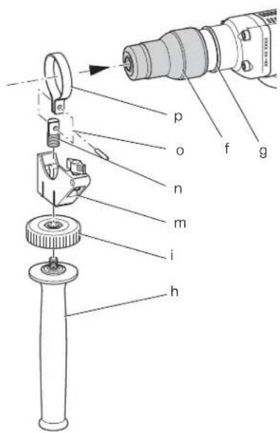
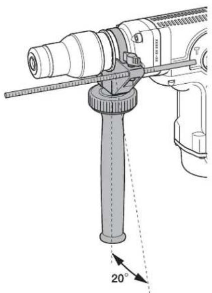
Figure 8 Figure 9
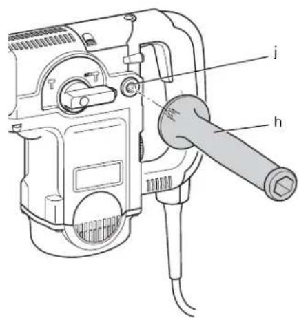
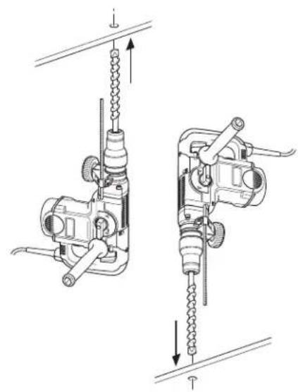
Figure 10 Figure 11
BOREHAMMER D25500, D25600
Tillykke!
MONTERING I FORPOSITION (FIG. 7, 8)
You have chosen a DEWALT tool. Years of experience, thorough product development and innovation make DEWALT one of the most reliable partners for professional power tool users.
Technical Data
| D25500 | D25600 | |||
| Voltage V 230 (U.K. & Ireland only) V | 230 230/115 | 230/115 | ||
| Types 2/3/2/3 | ||||
| Power input | W | 1,050 | 1,150 | |
| Impact energy | J | 1-9 1-10 | ||
| Total drilling range in concrete: | ||||
| solid bits | mm | 12-40 | 12-45 | |
| core bits | mm | 40-90 | 40-100 | |
| Optimum drilling range in concrete: | ||||
| solid bits | mm | 18-30 | 20-38 | |
| Chisel positions | 8 | 8 | ||
| Tool holder SDS Max | ® | SDS Max® | ||
| Weight | kg | 6.0 | 6.0 | |
| LkA (sound pressure) | dB(A) | 92 | 92 | |
| KwA (sound pressure uncertainty) | dB(A) | 3.0 | 3.0 | |
| LwA (sound power) | dB(A) | 103 | 103 | |
| KwA (sound power uncertainty) | dB(A) | 3.0 | 3.0 | |
Vibration total values (triax vector sum) determined according to EN 60745:
| Drilling into concreteVibration emission | |||
| value a h,HD = Uncertainty K = m/s2 | m/s2 | 18.0 | 19.0 |
| 1.8 | 2.0 | ||
| Chiselling | |||
| Vibration emission value a h,Cheq = Uncertainty K = m/s2 | m/s2 | 14.5 | 14.0 |
| 1.9 | 1.5 | ||
The vibration emission level given in this information sheet has been measured in accordance with a standardised test given in EN 60745 and may be used to compare one tool with another. It may be used for a preliminary assessment of exposure.

WARNING: The declared vibration emission level represents the main applications of the tool. However if the tool is used for different applications, with different accessories or poorly maintained, the vibration emission may differ. This may significantly increase the exposure level over the total working period.
An estimation of the level of exposure to vibration should also take into account the times when the tool is switched off or when it is running but not actually doing the job. This may significantly reduce the exposure level over the total working period.
Identify additional safety measures to protect the operator from the effects of vibration such as: maintain the tool and the accessories, keep the hands warm, organisation of work patterns.
| Fuses: | ||
| Europe | 230 V tools | 10 Amperes, mains |
| U.K. & Ireland | 230 V tools | 13 Amperes, in plugs |
| U.K. & Ireland | 115 V tools | 16 Amperes, mains |
Definitions: Safety Guidelines
The definitions below describe the level of severity for each signal word. Please read the manual and pay attention to these symbols.

DANGER: Indicates an imminently hazardous situation which, if not avoided, will result in death or serious injury.

WARNING: Indicates a potentially hazardous situation which, if not avoided, could result in death or serious injury.

CAUTION: Indicates a potentially hazardous situation which, if not avoided, may result in minor or moderate injury.
NOTICE: Indicates a practice not
related to personal injury which, if
not avoided, may result in property

damage.
Denotes risk of electric shock.

was risk of fire.
EC-DeclarationofConformity
MACHINERY DIRECTIVE

D25500,D25600
DEWALT declares that these products described under "technical data" are in compliance with: 98/37/EC (until Dec. 28, 2009), 2006/42/EC (from Dec. 29, 2009), EN 60745-1, EN 60745-2-6.
These products also comply with Directive 2004/108/EC. For more information, please contact DEWALT at the following address or refer to the back of the manual.
The undersigned is responsible for compilation of the technical file and makes this declaration on behalf of DEWALT.

Horst Grossmann
Vice President Engineering and Product
Development
D-65510, Idstein, Germany
27.07.09

WARNING: To reduce the risk of injury,
read the instruction manual.
General Power Tool SafetyWarnings

WARNING! Read all safety warnings
and instructions Failure to follow the
warnings and instructions may result in
electric shock, fire and/or serious injury.
SAVE ALL WARNING AND INSTRUCTIONS
FOR FUTURE REFERENCE
The term "power tool" in the warnings refers
to your mains-operated (corded) power tool or
battery-operated (cordless) power tool.
1) WORK AREA SAFETY
a) Keep work area clean and well lit.
Cluttered or dark areas invite accidents.
b) Do not operate power tools in explosive atmospheres, such as in the presence of flammable liquids, gases or dust. Power tools create sparks which may ignite the dust or fumes.
c) Keep children and bystanders away while
operating a power tool. Distractions can
cause you to lose control.
2) ELECTRICAL SAFETY
a) Power tool plugs must match the outlet. Never modify the plug in any way. Do not use any adapter plugs with earthed (grounded) power tools. Unmodified plugs and matching outlets will reduce risk of electric shock.
b) Avoid body contact with earthed or grounded surfaces such as pipes, radiators, ranges and refrigerators. There is an increased risk of electric shock if your body is earthed or grounded.
c) Do not expose power tools to rain or wet conditions. Water entering a power tool will increase the risk of electric shock.
d) Do not abuse the cord. Never use the cord for carrying, pulling or unplugging the power tool. Keep cord away from heat, oil, sharp edges or moving parts. Damaged or entangled cords increase the risk of electric shock.
e) When operating a power tool outdoors, use an extension cord suitable for outdoor use. Use of a cord suitable for outdoor use reduces the risk of electric shock.
If operating a power tool in a damp location is unavoidable, use a residual current device (RCD) protected supply. Use of an RCD reduces the risk of electric shock.
3) PERSONAL SAFETY
a) Stay alert, watch what you are doing and use common sense when operating a power tool. Do not use a power tool while you are tired or under the influence of drugs, alcohol or medication. A moment of inattention while operating power tools may result in serious personal injury.
b) Use personal protective equipment. Always wear eye protection. Protective equipment such as dust mask, non-skid safety shoes, hard hat, or hearing protection used for appropriate conditions will reduce personal injuries.
ENGLISH
c) Prevent unintentional starting. Ensure the switch is in the off position before connecting to power source and/or battery pack, picking up or carrying the tool. Carrying power tools with your finger on the switch or energising power tools that have the switch on invites accidents.
d) Remove any adjusting key or wrench before turning the power tool on. A wrench or a key left attached to a rotating part of the power tool may result in personal injury.
e) Do not overreach. Keep proper footing and balance at all times. This enables better control of the power tool in unexpected situations.
f) Dress properly. Do not wear loose clothing or jewellery. Keep your hair, clothing and gloves away from moving parts. Loose clothes, jewellery or long hair can be caught in moving parts.
g) If devices are provided for the connection of dust extraction and collection facilities, ensure these are connected and properly used. Use of dust collection can reduce dust-related hazards.
4) POWER TOOL USE AND CARE
a) Do not force the power tool. Use the correct power tool for your application. The correct power tool will do the job better and safer at the rate for which it was designed.
b) Do not use the power tool if the switch does not turn it on and off. Any power tool that cannot be controlled with the switch is dangerous and must be repaired.
c) Disconnect the plug from the power source and/or the battery pack from the power tool before making any adjustments, changing accessories, or storing power tools. Such preventive safety measures reduce the risk of starting the power tool accidentally.
d) Store idle power tools out of the reach of children and do not allow persons unfamiliar with the power tool or these instructions to operate the power tool. Power tools are dangerous in the hands of untrained users.
e) Maintain power tools. Check for misalignment or binding of moving parts, breakage of parts and any other condition that may affect the power tool's operation. If damaged, have the power tool repaired before use. Many accidents are caused by poorly maintained power tools.
f) Keep cutting tools sharp and clean. Properly maintained cutting tools with sharp cutting edges are less likely to bind and are easier to control.
g) Use the power tool, accessories and tool bits etc., in accordance with these instructions taking into account the working conditions and the work to be performed. Use of the power tool for operations different from those intended could result in a hazardous situation.
5) SERVICE
a) Have your power tool serviced by a qualified repair person using only identical replacement parts. This will ensure that the safety of the power tool is maintained.
Additional Specific Safety Rules for Rotary Hammers
- Wear ear protectors. Exposure to noise can cause hearing loss.
- Use auxiliary handles supplied with the tool. Loss of control can cause personal injury.
- Hold power tools by insulated gripping surfaces when performing an operation where the cutting tool may contact hidden wiring or its own cord. Contact with a "live" wire will make exposed metal parts of the tool "live" and shock the operator.
- Use clamps or other practical way to secure and support the workpiece to a stable platform. Holding the work by hand or against your body is unstable and may lead to loss of control.
- Wear safety goggles or other eye protection. Hammering operations cause chips to fly. Flying particles can cause permanent eye damage. Wear a dust mask or respirator for applications that generate dust. Ear protection may be required for most applications.
- Keep a firm grip on the tool at all times. Do not attempt to operate this tool without holding it with both hands. It is recommended that the side handle be used at all times. Operating this tool with one hand will result in loss of control. Breaking through or encountering hard materials such as re-bar may be hazardous as well. Tighten the side handle securely before use.
-
Do not operate this tool for long periods of time. Vibration caused by hammer action may be harmful to your hands and arms. Use gloves to provide extra cushion and limit exposure by taking frequent rest periods.
-
Do not recondition bits yourself. Chisel reconditioning should be done by an authorized specialist. Improperly reconditioned chisels could cause injury.
- Wear gloves when operating tool or changing bits. Accessible metal parts on the tool and bits may get extremely hot during operation. Small bits of broken material may damage bare hands.
- Never lay the tool down until the bit has come to a complete stop. Moving bits could cause injury.
- Do not strike jammed bits with a hammer to dislodge them. Fragments of metal or material chips could dislodge and cause injury.
- Slightly worn chisels can be resharpened by grinding.
- Keep the power cord away from the rotating bit. Do not wrap the cord around any part of your body. An electric cord wrapped around a spinning bit may cause personal injury and loss of control.
ResidualRisks
The following risks are inherent to the use of rotary hammers:
Injuries caused by touching the rotating parts or hot parts of the tool
In spite of the application of the relevant safety regulations and the implementation of safety devices, certain residual risks cannot be avoided. These are:
Impairment of hearing .
- Risk of squeezing fingers when changing the accessory.
Health hazards caused by breathing dust developed when working in concrete and/or masonry.
Markings on Tool
The following pictograms are shown on the tool:

Read instruction manual before use.

Wear ear protection.

Wear eye protection.
DATE CODE POSITION (FIG. 1)
The Date Code (r), which also includes the year of manufacture, is printed into the housing.
Example:
2009 XX XX
Year of Manufacture
Package Contents
The package contains:
1 Rotary hammer
1 Side handle
1 Depth adjustment rod
1 Tube of bit lubricant
1 Kitbox (K-models only)
1 Instruction manual
1 Exploded drawing
- Check for damage to the tool, parts or accessories which may have occurred during transport.
Take the time to thoroughly read and understand this manual prior to operation.
Description (fig. 1)
WARNING: Never modify the power tool or any part of it. Damage or personal injury could result.
a. On/off switch
b. Electronic speed and impact control dial
c. Service indicator LED (D25600)
d. Mode selector switch
e. Safety lock
f. Tool holder
g. Collar
h. Side handle
i. Side handle clamp wheel
j. Rear side handle position
k. Depth adjustment rod
- Main handle
INTENDED USE
The D25500/D25600 heavy-duty rotary hammers are designed for heavy-duty chipping and chasing applications in concrete, brick, stone and other masonry materials.
ENGLISH
DO NOT use under wet conditions or in presence of flammable liquids or gases.
These rotary hammers are professional power tools.
DO NOT let children come into contact with the tool. Supervision is required when inexperienced operators use this tool.
Soft Start Feature
The soft start feature allows to build up speed slowly, thus preventing the drill bit from walking off the intended hole position when starting. The soft start feature also reduces the immediate torque reaction transmitted to the gearing and the operator if the hammer is started with the drill bit in an existing hole.
Torque Limiting Clutch
The torque limiting clutch reduces the maximum torque reaction transmitted to the operator in case of jamming of a drill bit. This feature also prevents the gearing and electric motor from stalling.
The torque limiting clutch has been factory-set and cannot be adjusted.
Electronic Speed and Impact Control (fi g. 2)
The electronic speed and impact control (b) offers the following advantages:
- use of smaller accessories without risk of breakage
-
minimised break-out when chiselling or drilling in soft or brittle materials
-
optimal tool control for precise chiselling
Service Indicator LED (fi g. 2)
The red service indicator LED (c) lights up when the carbon brushes are nearly worn out to indicate that the tool needs servicing. After a further 8 hours of use the motor will automatically be shut off.
The carbon brushes are not user-serviceable.
Take the tool to an authorized DEWALT repair agent.
Electrical Safety
The electric motor has been designed for one voltage only. Always check that the power supply corresponds to the voltage on the rating plate.

Your DeWALT charger is double insulated in accordance with EN 60745; therefore no earth wire is required.

WARNING: 115 V units have to be operated via a fail-safe isolating transformer with an earth screen between the primary and secondary winding.
If the supply cord is damaged, it must be replaced by a specially prepared cord available through the DEWALT service organization.
Mains Plug Replacement (U.K. & Ireland Only)
If a new mains plug needs to be fitted:
- Safely dispose of the old plug.
- Connect the brown lead to the live terminal in the plug.
- Connect the blue lead to the neutral terminal.

WARNING: No connection is to be made to the earth terminal.
Follow the fitting instructions supplied with good quality plugs. Recommended fuse: 13 A.
Using an Extension Cable
An extension cord should not be used unless absolutely necessary. Use an approved extension cable suitable for the power input of your charger (see technical data). The minimum conductor size is 1mm ; the maximum length is 30m .
When using a cable reel, always unwind the cable completely.
ASSEMBLY AND ADJUSTMENTS

IG: To reduce the risk of injury, turn unit off and disconnect machine from power source before installing and removing accessories, before adjusting or changing set-ups or when making repairs. Be sure the trigger switch is in the OFF position. An accidental start-up can cause injury.
Inserting and Removing SDS Max® Accessories (fig. 3, 4)
This machine uses SDS Max drill bits and chisels (refer to the inset in fig. 4 for a cross-section of an SDS Max® bit shank).
- Clean and grease the bit shank.

CAUTION: Only apply a slight amount of lubricant to the bit shank. Do not apply lubricant to the machine.
- Insert the bit shank into the tool holder (f), and press and turn the bit slightly until the sleeve snaps into position.
- Pull on the bit to check if it is properly locked. The hammering function requires the bit to be able to move axially several centimetres when locked in the tool holder.
- To remove a bit pull back the tool holder locking sleeve (f) and pull the bit out of the tool holder.
Selecting the Operating Mode (fi g. 5)
The tool can be used in two operating modes:

Hammerdrilling: for concrete and masonry drilling operations.
Hammering only: for light chipping, chiselling and demolition applications. In this mode the tool can also be used as a lever to free a jammed drill bit.
- To select the operating mode, press the safety lock (e) and rotate the mode selector switch (d) until it is points to the symbol of the required mode.
- Release the safety lock and check that the mode selector switch is locked in place.
Indexing the Chisel Position (fi g. 5, 6)
The chisel can be indexed and locked into 8 different positions (fig. 6).
- Rotate the mode selector switch (d) until it points upward.
- Rotate the chisel in the desired position.
- Set the mode selector switch (d) to the "hammering only" position.
- Twist the chisel until it locks in position.
Setting the Electronic Speed and Impact Control Dial (fi g. 2)
Turn the dial (b) to the desired level. The higher the number, the greater the speed and impact energy. With dial settings from 1 (low) to 5 (full power) the tool is extremely versatile and adaptable for many different applications. The required setting is a matter of experience. e.g.:
when chiselling or drilling in soft, brittle materials or when minimum break-out is required, set the dial to 1 or 2 (low);
when breaking or drilling in harder materials, set the dial to 5 (full power).
D25600
With dial settings from 1 to 7 the tool allows a further fine-adjustment to the choice of application.
Assembling and Fitting the Side Handle (fi g. 7-10)
The side handle (h) can be mounted in front or in rear position on either side of the machine to suit both RH- and LH-users.
CAUTION: Always operate the tool with the side handle properly assembled.
MOUNTING IN FRONT POSITION (FIG. 7, 8)
- Snap the steel ring (p) over the collar (g) behind the tool holder (f). Squeeze both ends together, mount the bush (n) and insert the pin (o).
- Place the side handle clamp (m) and screw on the clamp wheel (j). Do not tighten.
- Screw the side handle (h) into the clamp wheel and tighten it.
- Rotate the side handle mounting assembly to the desired position. For drilling horizontally with a heavy drill bit, we recommend to place the side handle at an angle of approx. 20^ for optimum control (fig. 8).
- Lock the side handle mounting assembly in place by tightening the clamp wheel (i).
MOUNTING IN REAR POSITION (FIG. 9, 10)
The rear position is particularly useful when drilling overhead or down into a floor. Refer to fig. 10.
- Unscrew the side handle (h) and remove it from the front position. Leave the side handle mounting assembly in front position so that the depth adjustment rod can still be used.
- Screw the side handle directly into one of the rear side handle positions (j) on either side of the tool.
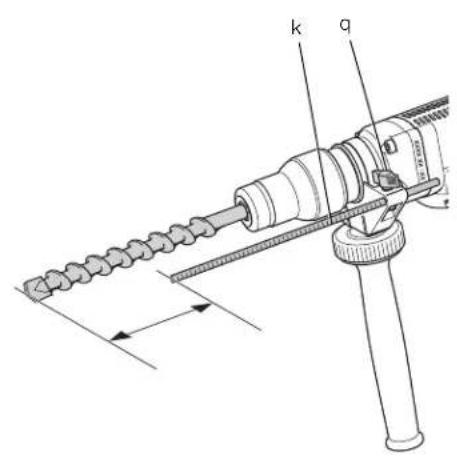
Setting the Drilling Depth (fi g. 11)
- Insert the required drill bit.
- Loosen the clamp nut (q) and fit the depth adjustment rod (k) through the hole in the side handle clamp.
- Push the drill bit into a surface at a right angle and adjust the depth adjustment rod (k) as shown.
- Tighten the clamp nut (q).
ENGLISH
OPERATION
Instructions for Use

Always observe the safety instructions and applicable regulations.
- tool with both hands.
Be aware of and wiring.
Apply only at the tool (approx. 20kg ). Excessive force does not speed up drilling or chiselling but decreases tool performance and may shorten tool life.
Proper Hand Position (fi g. 1)
WARNING: To reduce the risk of serious personal injury, ALWAYS use proper hand position as shown.
WARNING: To reduce the risk of serious personal injury, ALWAYS hold securely in anticipation of a sudden reaction.
Proper hand position requires one hand on the side handle (h), with the other hand on the main handle (l).
Switching On and Off (fi g. 1)
- To switch on the tool, press the on/off switch (a).
- To stop the tool, release the switch.
Drilling with a Solid Bit (fi g. 1)
- Insert the appropriate drill bit.
- Set the mode selector switch (d) to the "hammerdrilling" position.
- Set the electronic speed and impact control dial (b).
- Fit and adjust the side handle (h).
- If necessary, set the drilling depth.
- Mark the spot where the hole is to be drilled.
- Place the drill bit on the spot and switch on the tool.
- Always switch off the tool when work is finished and before unplugging.
Drilling with a Core Bit (fi g. 1)
- Insert the appropriate core bit.
- Assemble the centerdrill into the core bit.
- Set the mode selector switch (d) to the "hammerdrilling" position.
-
Turn the electronic speed and impact control dial (b) to a medium or high speed setting. Always use the 5. Fill and adjust the side handle (h).
-
Place the centerdrill on the spot and switch on the tool. Drill until the core penetrates into the concrete approx. 1 cm.
Pressure to. 7. Stop the tool and remove the center drill. Place the core bit back into the hole and continue drilling.
NOTE: When drilling through a structure thicker than the depth of the core bit, break away the round cylinder of concrete or core inside the bit at regular intervals.
- To avoid unwanted breaking away of concrete around the hole, first drill a hole the diameter of the centerdrill completely through the structure. Then drill the cored hole halfway from each side.
- Always switch off the tool when work is finished and before unplugging.
Chipping and Chiselling (fi g. 1)
- Insert the appropriate chisel and rotate it by hand to lock it into one of 8 positions.
- Set the mode selector switch (d) to the "hammering only" position.
- Set the electronic speed and impact control dial (b).
- Fit and adjust the side handle (h).
- Switch on the tool and start working.
- Always switch off the tool when work is finished and before unplugging.
MAINTENANCE
Your DEWALT power tool has been designed to operate over a long period of time with a minimum of maintenance. Continuous satisfactory operation depends upon proper tool care and regular cleaning.
WARNING: To reduce the risk of injury, turn unit off and disconnect machine from power source before installing and removing accessories, before adjusting or changing set-ups or when making repairs. Be sure the trigger switch is in the OFF position. An accidental start-up can cause injury.
Tool maintenance has to be carried out as soon as the indicator LED lights up.
This machine is not user-serviceable. Take the tool to an authorised DEWALT repair agent after approximately 80 hours of use. If problems occur before this time contact an authorised DEWALT repair agent.

Lubrication
Your power tool requires no additional lubrication.

Cleaning
WARNING: Blow dirt and dust out of the main housing with dry air as often as dirt is seen collecting in and around the air vents. Wear approved eye protection and approved dust mask when performing this procedure.
WARNING: Never use solvents or other harsh chemicals for cleaning the non-metallic parts of the tool. These chemicals may weaken the materials used in these parts. Use a cloth dampened only with water and mild soap. Never let any liquid get inside the tool; never immerse any part of the tool into a liquid.
Optional Accessories
WARNING: Since accessories, other than those offered by DEWALT, have not been tested with this product, use of such accessories with this tool could be hazardous. To reduce the risk of injury, only DEWALT, recommended accessories should be used with this product.
Various types of SDS Max drill bits and chisels are available as an option.
Consult your dealer for further information on the appropriate accessories.
Protecting the Environment

Separate collection. This product must not be disposed of with normal household waste.
Should you find one day that your DEWALT product needs replacement, or if it is of no further use to you, do not dispose of it with household waste. Make this product available for separate collection.

Separate collection of used products and packaging allows materials to be recycled and used again. Re-use of recycled materials helps prevent environmental pollution and reduces the demand for raw materials.
Local regulations may provide for separate collection of electrical products from the household, at municipal waste sites or by the retailer when you purchase a new product.
DEWALT provides a facility for the collection and recycling of DEWALT products once they have reached the end of their working life. To take advantage of this service please return your product to any authorised repair agent who will collect them on our behalf.
You can check the location of your nearest authorised repair agent by contacting your local DEWALT office at the address indicated in this manual. Alternatively, a list of authorised DEWALT repair agents and full details of our after-sales service and contacts are available on the Internet at: www.2helpU.com.
GUARANTEE
DEWALT is confident of the quality of its products and offers an outstanding guarantee for professional users of the product. This guarantee statement is in addition to and in no way prejudices your contractual rights as a professional user or your statutory rights as a private non-professional user. The guarantee is valid within the territories of the Member States of the European Union and the European Free Trade Area.
30 DAY NO RISK
SATISFACTION GUARANTEE
If you are not completely satisfied with the performance of your DEWALT tool, simply return it within 30 days, complete with all original components, as purchased, to the point of purchase, for a full refund or exchange. The product must have been subject to fair wear and tear and proof of purchase must be produced.
- ONE YEAR FREE SERVICE CONTRACT
If you need maintenance or service for your DEWALT tool, in the 12 months following purchase, it will be undertaken free of charge at an authorised DEWALT repair agent. Proof of purchase must be produced. Includes labour. Excludes accessories and spare parts unless failed under warranty.
- ONE YEAR FULL WARRANTY
If your DEWALT product becomes defective due to faulty materials or workmanship within 12 months from the date of purchase, DEWALT guarantees to replace all defective parts free of charge or - at our discretion - replace the unit free of charge provided that:
The product has not been misused;
The product has been subject to fair wear and tear;
- Repairs have not been attempted by unauthorised persons;
Proof of purchase is produced;
The product is returned complete with all original components.
If you wish to make a claim, contact your seller or check the location of your nearest authorised DEWALT repair agent in the DEWALT catalogue or contact your DEWALT office at the address indicated in this manual. A list of authorised DEWALT repair agents and full details of our after-sales service is available on the Internet at:
www.2helpU.com.
MARTILLO ROTATIVO D25500, D25600
Enhorabuena!
| aH,HD= | m/s2 | 18,0 | 19,0 |
| Incertezza K= | m/s2 | 1,8 | 2,0 |
Modalità scalpello
2006/42/EG (vanaf 29 December 2009);
WAARSCHUWING! Lees alle

1) SIKKERHET PÅ ARBEIDSPLASSEN
With dial settings from 1 to 7 the tool allows a further fine-adjustment to the choice of application.
Vice President Engineering and Product Development
DEWALT, Richard-Klinger-Strase 11
D-65510, Iolstein, Saksa
27.07.09

TUS: Vähenna tapaturmavaaraa
lukemalla ohje.
98/37/EC (till dec. 28, 2009), 2006/42/EC
franc dec.29,2009)EN 60745-1,EN 60745-2-6.
DATUMKODPLACERING (FIG. 1)
- ETT ARS FULLSTANDIG GARANTI
YIIOBnIawvE KIVOuV nEkToPiNxiac.

YtiooIwvei Kivduo Tnpkayias.
Anawon oumuoppwos TIG odnyie tsE.E.
OAHHIA NEPIMHXANIKOYEONAIEMOY

D25500,D25600
H taia DEWALT 0nawei 6ti Ta Tpoivota Tou Tepiapovta otny evotnta «Texika deoEv a
Oxidiaknvak eoumuopwnu ta Eng
TPOUTATA kai oynlyec:
98/37/EK (EwG TIG 28 EK. 2009), 2006/42/EK (aTTO TIC 29 EK. 2009), EN 60745-1, EN 60745-2-6
Ta Tpoiovta auta umuopwovtai etiango TE NTV O0NYA 2004/108/EK. TIA Tpeiaootepe TAnpoopie, TapaKaIoUe EITIOKIVWVnOte ME TNY DEWALT OTN YIpaKaTOW DIEUbUOn n avatpeTe OTO TiOW MEOs TOEYEIXIoiou.
O KATWU UTOYPAWV EIVAI UTUEBUVOC YA T N OuvTaN TOU TEXIKOU PAKAOU KAI TPAYATOTIOIE TNV TAPOUOA DHAOWN EK MEPOU CTS ETAPEIAC DEWALT.

Horst Grossmann
AvTIpOeDpO Tsmuo tsxavoloyia K a avattuNs Tpoiovtwv
Iavw OTo Epyaieio Biiaovraoi I TapaKaTu 8IKOVEc:

AiaBaeTo EYExPiio OOnyiv Tpiv aTn xpno

ΦopATE TPOOTATEUTIKA aKOUOTIKA.

OII TEPIOPTOPKIEC OPOE C Eiva EITAYEAATIKA nAekpiKa epyaeia.
MHN ETITIETTE OE TAIIOVAEPBOU O'ETIAPH ME TO EpyaaEO. AATIIEITAI ETITINPON, OTAV AUTO TO EpyaaEO xnpoiOTIEiTAtO ATTEIPOUX pnoTcE.
Duvatotnta aalakns Ekkivno
H duvarotnta maakns ekkvnonc etttptettnv apyn auon nts taxutnac, attonpctovtac etai n metatotion tou purtaviou ao tnv entbunm thoan otnc katnv ekkvnon. Etnians, nduvarotnta maakns ekkvnons elattweivn nv aean avifpaon potns otpesn Tou metaepetar oto outa na metaaooc kivnonk kto xeiipotn, eav to opupi ekivnae ie to purtavou 0dpattavou oeia utapxouoa otn.
H\xexwipotn oulambdaoyn
XpOoiOToinIevwTpoovTow
KAI OUKEUAOW EITITPETTEI
TnV avakukawon kai
ETTavaxpoaiotoinTowuikwv.
H eTavaaNnTikxPnON TwV
avakukwmevwwuikwβonθa
ouAoyn kai avakukwon Tov Tpoiovtow
deltavon www.2helpU.com.
EETYH2H
H DEWALT Exe iEiIOIOoovn OTNV TIOIOTNa
Tuw TPoiOvivw TNS KAI TPoOpePe iia
EcaipetIKyEYUnON YIA TOUs ETAYeApaties
XpnoTeC TOW TPioOvTOc. H TAPouOa DnAwn
EyYUnOns ATOTEAEI TPooBKnK KAI SEV BAATTIE
KATA KAVEAV TPOTTa BkAiwmuata Boaei
OuMaOn TPO EXETe Wc EITAYeApatiac
XpnoTns n Ta VOpua DkAiWiAta OAC Ws
IDIWNTs, m EITAYeApatiac, XpnoTns. H
TPapouOa EyyUnON IxUeEVTOV TFW TEPiOxWv
BdkaiOoOlaTsw KpatW MEwV TNS
EupWtaikNc EvwOn KAI TNC EupWtaikNc
ZwVNs EAEuOePwv SuVaALayWv.
- ETTYEH IKANONIOIHZH 30 HMEPQN XQPIE KINADYNO
Eavveivete Tnnpwscavotoinueoia tno tv atdoon tou epyaieou DEWALT, aIwcs ETIOPEVE TO ETVc 30 npewv, Tnpeoc OTWs ayopaoTKe ME oAa Ta Tmuata KAI eapntuaTO, OTO aneio ayopac, yia va ac EtniOpaei To suVoloTwv xnpuawv ia avtaalayn. To tpioiov TPTEIvapeei EUoynpOpaKai TPTEIva UNTAPXe iAtoideiayopac.