SE 17200 RT - Milling machine METABO - Free user manual and instructions
Find the device manual for free SE 17200 RT METABO in PDF.
| Product type | Grinder (satiner, polisher, brush) |
| Brand | Metabo |
| Model | SE 17200 RT |
| Power supply | Mains (230 V~, 50 Hz) |
| Rated input power (P1) | See nameplate |
| Output power (P2) | See nameplate |
| No-load speed (n0) | From 800 to 3000 rpm (adjustable in 6 positions) |
| Permissible diameter of abrasive element (D) | See page 3 of technical data |
| Maximum grinding wheel width (B_max) | See page 3 of technical data |
| Spindle thread (M) | See page 3 of technical data |
| Spindle length (l) | See page 3 of technical data |
| Electronic system | VTC (speed stabilization under load), overload protection |
| Weight (without cable) | See page 3 of technical data |
| Protection class | II (double insulation) |
| Main functions | Satin finishing, matting, structuring, brushing, polishing, smoothing, grinding, deburring |
| Machinable materials | Metal, wood, synthetic materials (dry machining only) |
| Recommended accessories | Wire brushes, non-woven drums, abrasive wheels, abrasive belts, etc. (see chapter 12) |
| Included safety equipment | Additional handle, protective guard, spindle lock button |
| Maintenance and cleaning | Regularly clean ventilation slots with dry compressed air (machine unplugged) |
| Repairs | Have a qualified electrician carry out repairs; use only genuine Metabo parts |
| Warranty and environment | Follow recycling instructions (WEEE, batteries) |
Frequently Asked Questions - SE 17200 RT METABO
User questions about SE 17200 RT METABO
0 question about this device. Answer the ones you know or ask your own.
Ask a new question about this device
Download the instructions for your Milling machine in PDF format for free! Find your manual SE 17200 RT - METABO and take your electronic device back in hand. On this page are published all the documents necessary for the use of your device. SE 17200 RT by METABO.
USER MANUAL SE 17200 RT METABO
natural_image
Exterior view of a metalworking power tool with visible brand name 'metabo' and control panel (no text or symbols on the tool itself)
Chief Technology Officer Koki Holdings Co., Ltd.
*4) Metabowerke GmbH - Metabo-Allee 1 - 72622 Nuertingen, Germany
text_image
Diagram showing finger pressing a button with numbered arrows and directional arrows indicating movement or forceOriginal instructions
1. Declaration of Conformity
We, being solely responsible, hereby declare that these burnishing machines, identified by type and serial number *1), meet all relevant requirements of directives *2) and standards *3). Technical documents for *4) - see page 3.
For UK only:
UK We as manufacturer and authorized person to CA compile the technical file, see *4) on page 3, hereby declare under sole responsibility that these burnishing machines, identified by type and serial number *1) on page 3, fulfill all relevant provisions of following UK Regulations S.I. 2016/1091, S.I. 2008/1597, S.I. 2012/3032 and Designated Standards *3).
2. Specified Conditions of Use
The burnishing machine is suited for
- burnishing, deadening, structuring and brushing,
• polishing and smoothing, - sanding and deburring the following materials: metal, wood and plastics.
It is for dry processing only.
The user bears sole responsibility for any damage caused by inappropriate use.
Generally accepted accident prevention regulations and the enclosed safety information must be observed.
3. General Safety Information

For your own protection and for the protection of your power tool, pay attention to all parts of the text that are marked with this symbol!

WARNING – Read the operating instructions to reduce the risk of injury.

WARNING – Read all safety warnings, instructions, illustrations and
specifications provided with this power tool.
Failure to follow all instructions listed below may result in electric shock, fire and/or serious injury.
Save all warnings and instructions for future reference.
Always include these documents when passing on your power tool.
4. Special Safety Instructions
4.1 Safety Warnings Common for Grinding, Sanding, Wire Brushing or Polishing Operations:
a) This power tool is intended to function as a grinder, sander, wire brush and polisher. Read all safety warnings, instructions, illustrations and specifications provided with this power
tool. Failure to follow all instructions listed below may result in electric shock, fire and/or serious injury.
b) Operations such as hole cutting or cutting-off are not to be performed with this power tool. Operations for which the power tool was not designed may create a hazard and causepersonal injury.
c) Do not convert this power tool to operate in a way which is not specifically designed and specified by the tool manufacturer. Such a conversion may result in a loss of control and cause serious personal injury.
d) Do not use accessories which are not specifically designed and specified by the tool manufacturer. Just because the accessory can be attached to your power tool, it does not assure safe operation.
e) The rated speed of the accessory must be at least equal to the maximum speed marked on the power tool. Accessories running faster than their rated speed can break and fly apart.
f) The outside diameter and the thickness of your accessory must be within the capacity rating of your power tool. Incorrectly sized accessories cannot be adequately controlled.
g) The dimensions of the accessory mounting must fit the dimensions of the mounting hardware of the power tool. Accessories that do not match the mounting hardware of the power tool will run out of balance, vibrate excessively and may cause loss of control.
h) Do not use a damaged accessory. Before each use inspect the accessory such as abrasive wheels for chips and cracks, backing pad for cracks, tear or excess wear, wire brush for loose or cracked wires. If power tool or accessory is dropped, inspect for damage or install an undamaged accessory. After inspecting and installing an accessory, position yourself and bystanders away from the plane of the rotating accessory and run the power tool at maximum no-load speed for one minute. Damaged accessories will normally break apart during this test time.
i) Wear personal protective equipment. Depending on application, use face shield, safety goggles or safety glasses. As appropriate, wear dust mask, hearing protectors, gloves and workshop apron capable of stopping small abrasive or workpiece fragments. The eye protection must be capable of stopping flying debris generated by various applications. The dust mask or respirator must be capable of filtrating particles generated by the particular application. Prolonged exposure to high intensity noise may cause hearing loss.
j) Keep bystanders a safe distance away from work area. Anyone entering the work area must wear personal protective equipment. Fragments of workpiece or of a broken accessory may fly away
and cause injury beyond immediate area of operation.
k) Position the cord clear of the spinning accessory. If you lose control, the cord may be cut or snagged and your hand or arm may be pulled into the spinning accessory.
I) Hold the power tool by insulated gripping surfaces only, when performing an operation where the cutting accessory may contact hidden wiring or its own cord. Contact with a "live" wire will also make exposed metal parts of the power tool "live" and could give the operator an electric shock.
m) Never lay the power tool down until the accessory has come to a complete stop. The spinning accessory may grab the surface and pull the power tool out of your control.
n) Do not run the power tool while carrying it at your side. Accidental contact with the spinning accessory could snag your clothing, pulling the accessory into your body.
o) Regularly clean the air vents of your power tool. The motor's fan will draw the dust inside the housing and excessive accumulation of powdered metal may cause electrical hazards.
p) Do not operate the power tool near flammable materials. Sparks could ignite these materials.
q) Do not use accessories that require liquid coolants. Using water or other liquid coolants may result in electrocution or shock.
4.2 Kickback and related warnings
Kickback is a sudden reaction to a pinched or snagged rotating wheel, backing pad, brush or any other accessory. Pinching or snagging causes rapid stalling of the rotating accessory which in turn causes the uncontrolled power tool to be forced in the direction opposite of the accessory's rotation at the point of the binding.
For example, if an abrasive wheel is snagged or pinched by the workpiece, the edge of the wheel that is entering into the pinch point can dig into the surface of the material causing the wheel to climb out or kick out. The wheel may either jump toward or away from the operator, depending on direction of the wheel's movement at the point of pinching. Abrasive wheels may also break under these conditions.
Kickback is the result of power tool misuse and/or incorrect operating procedures or conditions and can be avoided by taking proper precautions as given below.
a) Maintain a firm grip with both hands on the power tool and position your body and arms to allow you to resist kickback forces. Always use auxiliary handle, if provided, for maximum control over kickback or torque reaction during start-up. The operator can control torque reactions or kickback forces, if proper precautions are taken.
b) Never place your hand near the rotating accessory. Accessory may kickback over your hand.
c) Do not position your body in the area where power tool will move if kickback occurs. Kickback will propel the tool in direction opposite to the wheel's movement at the point of snagging.
d) Use special care when working corners, sharp edges etc. Avoid bouncing and snagging the accessory. Corners, sharp edges or bouncing have a tendency to snag the rotating accessory and cause loss of control or kickback.
e) Do not attach a saw chain woodcarving blade, segmented diamond wheel with a peripheral gap greater than 10 mm or toothed saw blade. Such blades create frequent kickback and loss of control.
4.3 Safety warnings specific for sanding operations:
a) Use properly sized sanding disc paper. Follow the manufacturer's recommendations when selecting sanding paper. Larger sanding paper extending too far beyond the sanding pad presents a laceration hazard and may cause snagging, tearing of the disc or kickback.
4.4 Safety warnings specific for polishing operations:
a) Do not allow any loose portion of the polishing bonnet or its attachment strings to spin freely. Tuck away or trim any loose attachment strings. Loose and spinning attachment strings can entangle your fingers or snag on the workpiece.
4.5 Safety warnings specific for wire brushing operations:
a) Be aware that wire bristles are thrown by the brush even during ordinary operation. Do not overstress the wires by applying excessive load to the brush. The wire bristles can easily penetrate light clothing and/or skin.
b) If the use of a guard is specified for wire brushing, do not allow any interference of the wire wheel or brush with the guard. Wire wheel or brush may expand in diameter due to work load and centrifugal forces.
4.6 Additional Safety Instructions:
Flying sparks are created when sanding metal. Ensure that no persons are in danger. Due to the risk of fire, all combustible materials must be removed from the work area (area affected by flying sparks).

During machining, of metals in particular, conductive dust can form deposits inside the machine. This can lead to the transfer of electrical energy onto the machine housing. This can mean a temporary danger of electric shocks. This is why it is necessary when the machine is running to blow compressed air through the rear ventilation slots of the machine regularly, frequently and thoroughly. Here, the machine must be held firmly.
It is recommended to use a stationary extraction system and to place a ground fault circuit interrupter
ENGLISHen
(GFCI) downstream. When the machine is shut down via the GFCI, it must be checked and cleaned. See the 10. Cleaning chapter for more information on cleaning the motor.
Wear tight-fitting protective gloves and clothing. Do not wear loose clothing or jewellery. Keep your hair and clothing away from moving parts. Loose clothes, jewellery or long hair can be caught in moving parts.

WARNING – Always wear protective goggles.

Wear ear protectors.

WARNING – Always operate the power tool with two hands.
Use elastic cushioning layers if they have been supplied with the sanding media and if required.
Observe the specifications of the tool or accessory manufacturer!
Accessories must be stored and handled with care in accordance with the manufacturer's instructions.
Ensure that accessories are installed in accordance with the manufacturer's instructions.
The tool continues running after the machine has been switched off.
Only use the machine if the protective cover is in place.
Do not use separate reducing bushings or adapters to adapt tools with a large hole.

Switch on the device before it is placed against the workpiece! The workpiece must
lay flat and be secured against slipping, e.g. using clamps. Large workpieces must be sufficiently supported. Otherwise there is a risk of the workpiece being thrown out of place in an uncontrolled manner.
If accessories with threaded inserts are used, the end of the spindle may not touch the base of the hole on the sanding tool. Make sure that the thread in the accessory is long enough to accommodate the full length of the spindle. The thread in the accessory must match the thread on the spindle. See page 3 and chapter 15. Technical
Specifications for more information on the spindle length and thread.
Damaged, eccentric or vibrating tools must not be used.
A damaged or cracked side handle must be replaced. Never operate the machine with a defective additional handle.
Only use the machine if the protective cover is in place.
Always guide the machine with both hands on the handles provided.

Do not reach into rotating accessories!
4.7 Special safety instructions for mains powered machines:
Pull the plug out of the socket before making any adjustments, changing tools, carrying out maintenance or cleaning.
Before connecting the mains plug, make sure that the machine is switched off.
Use of a fixed extractor system is recommended. Always install an RCD with a maximum trip current of 30 mA upstream. If the angle grinder is shut down via the GFCI, it must be checked and cleaned. See Chapter 9. Maintenance.
4.8 Special safety instructions for cordless machines:
Remove the battery pack from the machine before making any adjustments, changing tools, maintaining or cleaning.
Before fitting the battery pack, make sure that the machine is switched off.

Protect battery packs from water and moisture!
Do not expose battery packs to fire!
Do not use faulty or deformed battery packs! Do not open battery packs!
Do not touch or short circuit battery pack contacts!

A slightly acidic, flammable fluid may leak from defective Li-Ion battery packs!

If battery fluid leaks out and comes into contact with your skin, rinse immediately with plenty of water. If battery fluid leaks out
and comes into contact with your eyes, wash them with clean water and seek medical attention immediately!
If the machine is defective, remove the battery pack from the machine.
Transport of Li-Ion battery packs:
The shipping of Li-Ion battery packs is subject to laws related to the carriage of hazardous goods (UN 3480 and UN 3481). Inform yourself of the currently valid specifications when shipping Li-Ion battery packs. If necessary, consult your freight forwarder. Certified packaging is available from Metabo.
Only send the battery pack if the housing is intact and no fluid is leaking. Remove the battery pack from the machine for sending. Prevent the contacts from short-circuiting (e.g. by protecting them with adhesive tape).
Reducing dust exposure:

WARNING - Some dust created by power sanding, sawing, grinding, drilling, and other
construction activities contains chemicals known to cause cancer, birth defects or other reproductive harm. Some examples of these chemicals are:
- Lead from lead-based paints,
- crystalline silica from bricks and cement and other masonry products, and
- arsenic and chromium from chemically treated lumber.
Your risk from these exposures varies, depending on how often you do this type of work. To reduce your exposure to these chemicals, work in a well-ventilated area, and work with approved safety equipment, such as those dust masks that are specially designed to filter out microscopic particles.
This also applies to dust from other materials, such as some timber types (like oak or beech dust), metals, asbestos. Other known diseases are e.g. allergic reactions, respiratory diseases. Do not let dust enter the body.
Observe the relevant guidelines and national regulations for your material, staff, application and place of application (e.g. occupational health and safety regulations, disposal).
Collect the particles generated at the source, avoid deposits in the surrounding area.
Use suitable accessories for special work. In this way, fewer particles enter the environment in an uncontrolled manner.
Use a suitable extraction unit.
Reduce dust exposure with the following measures:
- do not direct the escaping particles and the exhaust air stream towards yourself or nearby persons or towards dust deposits,
- use an extraction unit and/or an air purifier,
- ensure good ventilation of the workplace and keep it clean using a vacuum cleaner. Sweeping or blowing stirs up dust.
Vacuum or wash protective clothing. Do not blow, beat or brush protective gear.
5. Overview
See page 2.
1 Additional handle
2 Safety guard
3 Handle bar
4 Clamping lever
5 Screw
6 Handle
7 Sliding on/off switch*
8 Spindle locking button
9 Spindle
10 Electronic signal indicator
11 Speed adjustment wheel*
12 Pushbutton switch*
13 Tool fixing screw
14 Tensioning spindle (with 2 captive fitted keys)
15 Open-ended spanner
16 Distance sleeves (for tools shorter than the tensioning spindle)
17 Battery pack release button*
18 Dust filter*
19 Battery pack *
20 Button of capacity display*
21 Capacity and signal display*
22 Locking button
*depends on features / model
6. Initial Operation
6.1 Assembly, setting
See page 2, fig. A.
Attach and set handle bar
Put the handle bar (3) on the gearbox flange (put on the right way around, see page 2 fig. A: clamping lever (4) shows forwards).

The handle bar (3) must be fitted as far as the limit stop on the gearbox flange.
After releasing the clamping lever (4), the handle bar (3) can be turned to the desired position. Firmly tighten the clamping lever (4) again. The position of the lever might need to be changed for this purpose.
The position of the lever (4) can be changed without turning the clamping screw. For this purpose, raise the lever, turn it and then lower the lever again (see page 2, fig. B).

When working, always position the lever (4) in a way that it cannot come into contact with the
Attach and set guard
Attach the guard (2) as shown using the side handle (1) and the screws (5) at the handle bar (3).
Keep the distance to the tool as short as possible.
Tighten the additional handle by applying force.
Attach tensioning spindle
Holding the spindle locking button down, screw the tensioning (14) spindle (8) onto the spindle (9) and tighten with an open-ended spanner (15).
6.2 For mains powered machines only Connection to Power Mains

Before commissioning, check that the rated mains voltage and mains frequency stated on type plate match your power supply.

Always install an RCD with a maximum trip current of 30 mA upstream.
The red electronics signal indicator (10) lights up briefly when the mains plug is inserted in the socket, indicating readiness for operation.
The VTC electronics make material-compatible work possible and an almost constant speed, even under load.
The best way to determine the ideal speed setting is by performing a test.
6.3 For cordless machines only
Dust filter

Always fit the dust filter (18) if the surroundings are heavily polluted.

The machine heats up faster when the dust filter (18) is fitted. It is protected by the tronics system from overheating.
Attaching:
Fit the dust filter (18) as shown.
Removal:
ENGLISHen
Holding the dust filter (18) at the edges, raise it slightly and then pull it downwards and remove.
Rotating battery pack
See illustration E on page 2.
The rear section of the machine can be rotated 270^ in 3 stages, thus allowing the machine's shape to be adapted to the working conditions. Only operate the machine when it is in an engaged position.
First press the locking button (22), rotate the rear part of the machine while keeping it pressed. Release the button while rotating the machine. The locking mechanism must engage with an audible "click".
Battery pack
Charge the battery pack (19) before use.
Recharge the battery pack if performance diminishes.
from 'supplement':
Battery packs have a capacity and signal indicator (21) (depends on design variant):
The ideal storage temperature is between 10^ C and 30^ C.
"Li-Power, LiHD" lithium ion battery packs have a capacity and signal indicator (21):
- Press the button (20), the LEDs indicate the charge level.
- The battery pack is almost empty and must be recharged if one LED is flashing.
Removing and inserting the battery pack
To remove: Press the battery pack release button (17) and pull the battery pack () downwards and out.
To insert: Slide the battery pack () in until it engages.
7. Use
7.1 Setting speed
The speed can be preset and modified using the setting wheel (11). For a list of speeds, see the table on page 3.
SE 17-200 RT
The speed can be preset via the thumb-wheel (11) and is infinitely variable.
Positions 1-6 correspond approximately to the following no-load speeds:
1 ...... 800 / min 4...... 2150 / min
2 ...... 1250 / min 5...... 2600 / min
3 ...... 1700 / min 6...... 3000 / min
SVB 18 LTX BL 200
The speed can be preset via the thumb-wheel (11) and is infinitely variable.
Positions 1-6 correspond approximately to the following no-load speeds:
1 ...... 600 / min 4...... 1770 / min
2 ..... 960 / min 5..... 2170 / min
3 ...... 1360 / min 6...... 2500 / min
7.2 Switching on and off

Always guide the machine with both hands.

Switch on first, then guide the accessory towards the workpiece.

The machine must not be allowed to draw in additional dust and shavings. When switching
the machine on and off and keep it away from dust deposits. After switching off the machine, only place it down when the motor has come to a standstill.

In continuous operation, the machine continues running if it is forced out of your
hands. Therefore, always hold the machine with both hands using the handles provided, stand securely and concentrate.
SVB 18 LTX BL 200:
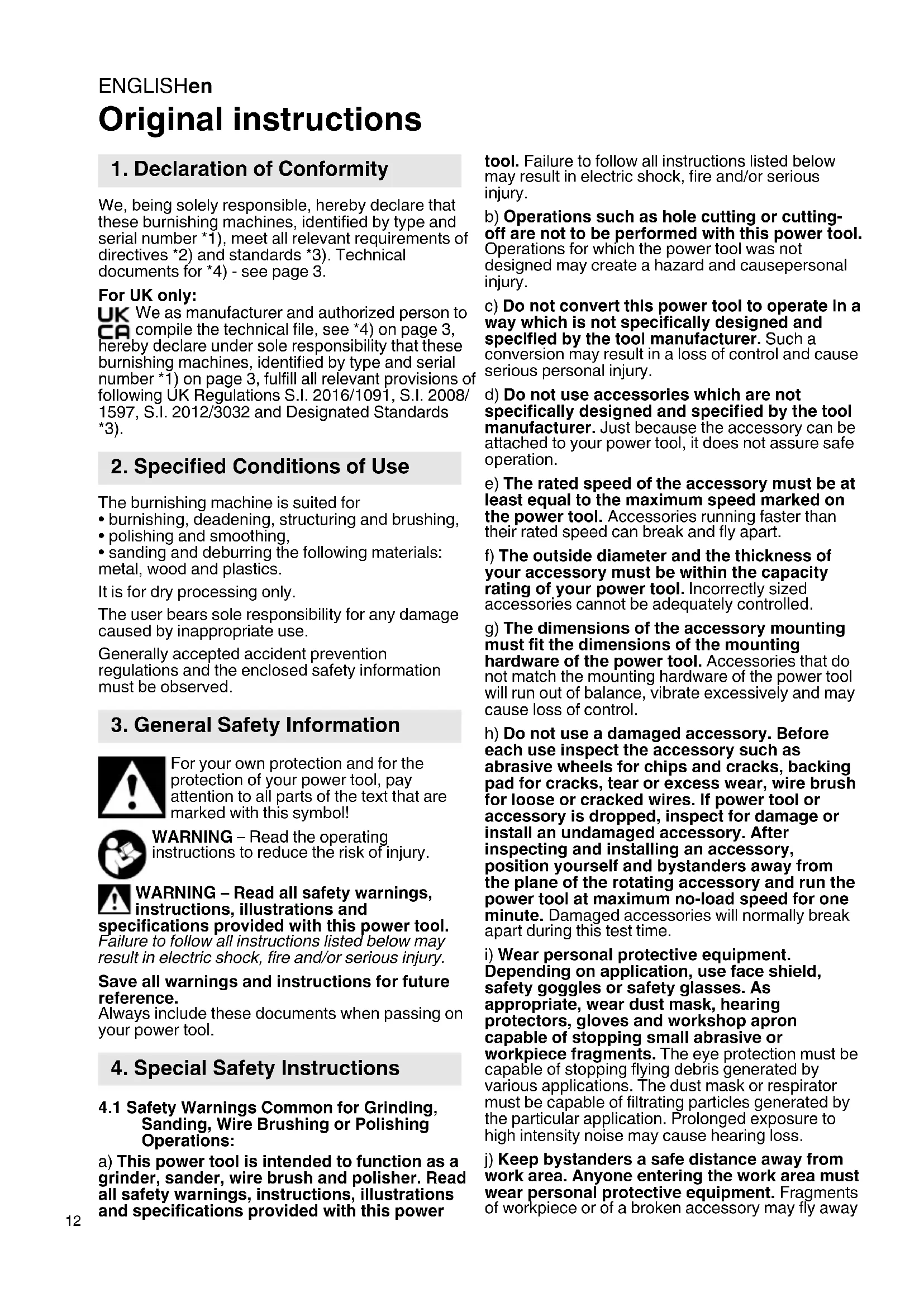
text_image
Diagram showing finger movement with numbered arrows and directional arrows, likely illustrating a motion or process flow.Switching on: push the slide switch (7) forwards. For continuous operation, tilt it downwards until it engages.
Switching off: press the rear end of the slide switch (7) and release it.
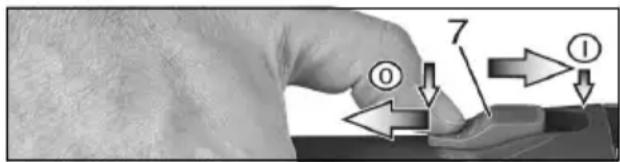
PE 17-200 RT:
Torque activation (with dead man's lever)
text_image
12 ① ②Switching on: Slide the trigger switch (12) forwards and then push the trigger switch (12) upwards.
Switching off: Release the trigger switch (12).
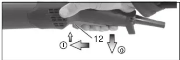
Continuous operation (depending on features)
text_image
12 ① ②Switching on: Switch the machine on as described above. Now slide the trigger switch (12) forwards again and release in the front position to lock the trigger switch (12) (continuous operation).
Switching off: Push the trigger switch (12) upwards and release.
8. Attaching the tools, working notes

Press in the spindle locking knob (8) only when the spindle is stationary!
8.1 Tools with threaded insert:
- Remove the tensioning spindle (14) if necessary. Press in spindle locking button (8) and hold in place. Unscrew the tensioning spindle using the open-ended spanner (15).
- Press in spindle locking button and hold in place.
- Screw the tool onto the spindle and tighten.
8.2 Tools for tensioning spindle:
- Attach the tensioning spindle (14) if necessary. Press in spindle locking button (8) and hold in place. Tighten the tensioning spindle using the open-ended spanner (15).
- Slide the tool onto the tensioning spindle.
- Press in spindle locking button (8) and hold in place.
- Screw the tool fixing screw (13) onto the tensioning spindle and tighten (the spindle locking knob engages and the tool can be secured).
If the tools used are shorter than the tensioning spindle, insert the relevant distance sleeves (16). This is the only way to properly secure the tool.
8.3 Working Directions
Sanding, polishing, working with wire brushes:
Apply moderate pressure on the machine and move it to and fro across the surface
9. Maintenance
Disconnect the mains plug or remove the battery pack from the machine before starting any maintenance work.
Particles may become deposited inside the power tool during operation. This impairs the cooling of the power tool. Conductive build-up can impair the protective insulation of the power tool and create an electrical hazard.
The power tool should be cleaned regularly, often and thoroughly through all front and rear air vents using a vacuum cleaner or by blowing in dry air. Prior to this operation, separate the power tool from the power source and wear protective glasses and dust mask.
10. Cleaning
Particles may become deposited inside the power tool during operation. This impairs the cooling of the power tool. Conductive build-up can impair the protective insulation of the power tool and create an electrical hazard.
The power tool should be cleaned regularly, often and thoroughly through all front and rear air vents using a vacuum cleaner or by blowing in dry air. Prior to this operation, separate the power tool from the power source and wear protective glasses and a suitable dust mask. Ensure appropriate suction is available when blowing out vents.
11. Troubleshooting
11.1 Mains powered machines
The electronic signal indicator (10) lights up and the load speed decreases (not W...RT). There is too much load on the machine! Run the machine in idling until the electronic signal indicator switches off.
The machine does not start. The electronic signal indicator (10) (depending on the model) flashes. Restart protection is active. If the mains plug is inserted with the machine switched on or if the power supply is restored following an interruption, the machine does not start up. Switch the machine off and back on again.
11.2 Cordless machines
The electronic signal display (10) flashes and the machine does not start.
The battery pack is empty; the temperature is too high or the restart protection has triggered. Switch the machine off and back on again. The machine will not start if the battery pack is inserted while the machine is on. When using a battery pack that is not part of CAS, the machine will not start.
The electronic signal display (10) is permanently on.
There has been an overload while working, therefore the performance may be reduced temporarily. Reduce working pressure.
Electronic safety shutdown: the machine has SHUT DOWN by itself. If the slew rate of the current is too high (for example, if the machine suddenly seizes or kickback occurs), the machine switches off. Switch off the machine. Switch it on again and continue to work as normal. Try to prevent the machine from seizing.
12. Accessories
Always use the suitable accessory for the application.
Application:
1 = burnishing, texturing and matting stainless steel surfaces and non-ferrous metals
2 = removing scratches and cleaning surfaces
3 = polishing, fine grinding, deburring
4 = smoothing / roughening wooden materials
Accessories:
1.1 = sanding fleece roller
1.2 = fleece sanding sleeve (only in conjunction with expansion roller)
1.3 = flap grinding wheel
1.4 = flap/fleece grinding wheel
1.5 = fleece grinding wheel
1.6 = rubber grinding wheel
1.7 = "Metabo Pyramid", sanding belt 90 x 100 mm
1.8 = Inox steel wire round brushes
1.9 = plastic round brushes
2.1 = sanding fleece roller
2.2 = fleece sanding sleeve (only in conjunction with
ENGLISHen
expansion roller)
2.3 = hard fleece grinding wheel
2.4 = flap grinding wheel
2.5 = flap/fleece grinding wheel
2.6 = rubber grinding wheel
2.7 = zircon corundum sanding belt, 90 x 100 mm (only in conjunction with expansion roller)
2.8 = brass steel wire round brushes
2.9 = Inox steel wire round brushes
3.1 = fleece sanding sleeve (only in conjunction with expansion roller)
3.2 = fleece grinding wheel
3.3 = fleece belts
3.4 = felt belt 30x600 mm (only in conjunction with sanding belt roll 623529000)
3.5 = Inox steel wire round brushes
3.6 = plastic round brushes
3.7 = polishing rings and abrasive pastes
4.1 = flap/fleece grinding wheel
4.2 = fleece grinding wheel
4.3 = brass steel wire round brushes
4.4 = plastic round brushes
4.5 = fibre round brush
Only use original Metabo battery packs and Metabo accessories.
Use only accessories that fulfil the requirements and specifications listed in these operating instructions.
Chargers: ASC 55, ASC 145, etc.
Battery packs with different capacities. Buy battery packs only with voltage suitable for your power tool.
Order no.: 625368000 5.5 Ah (LiHD)
Order no.: 625369000 8.0 Ah (LiHD)
Order no.: 625549000 10.0 Ah (LiHD)
etc.
Order no.: 625591 ..... 4.0 Ah (LiPOWER)
Order no.: 625028 ..... 5.2 Ah (LiPOWER) etc.
Polishing rings
Auxiliary materials for polishing
See www.metabo.com or the catalogue for a complete range of accessories.
13. Repairs

Repairs to electrical tools must only be carried out by qualified electricians!
A defective mains cable must be replaced only with a special, original mains cable from Metabo available from the Metabo service.
Contact your local Metabo representative if you have Metabo power tools requiring repairs. For addresses see www.metabo.com.
You can download a list of spare parts from www.metabo.com.
14. Environmental Protection
The generated sanding dust may contain harmful substances: dispose of appropriately.
Observe national regulations on environmentally compatible disposal and on the recycling of disused machines, packaging and accessories.
Packaging materials must be disposed of according to their labelling in accordance with municipal guidelines. Further information can be found at www.metabo.com in the “Service” section.

Only for EU countries: never dispose of power tools in your household waste! In accordance with
European Directive 2012/19/EU relating to electrical and electronic waste and implementation of national law, used electrical tools must be collected separately and disposed of in an environmentally friendly manner at recycling centres.
Special notes regarding cordless machines:
Battery packs may not be disposed of with regular waste. Return faulty or used battery packs to your Metabo dealer!
Do not allow battery packs to come into contact with water!
Discharge the battery pack in the power tool before disposal. Prevent the contacts from short-circuiting (e.g. by protecting them with adhesive tape).
15. Technical Specifications
Explanatory notes regarding the specifications on page 3. Subject to change in accordance with technical progress.
D = Permitted wheel diameter
B_max = maximum wheel width
M = Spindle thread
I = Length of spindle
n_0 =No-load speed
U=Voltage of battery pack
P_1 =Rated input power
P_2 =Power output
m=Weight with smallest battery pack/weight without cord
Measured values determined in conformity with EN 62841.
--- Direct current (cordless machines)
\~ Alternating current (mains powered machines)

Machine in protection class II (mains powered machines)
* SE 17-200 RT: High-energy, high-frequency interferences can cause speed fluctuations. The fluctuations disappear, however, as soon as the interference fades away.
The technical specifications quoted are subject to tolerances (in compliance with relevant valid standards).

Emission values
These values make it possible to assess the emissions from the power tool and to compare different power tools. The actual load may be higher or lower depending on operating conditions, the condition of the power tool or the accessories used. Please allow for breaks and periods when the load is lower for assessment purposes. Arrange protective measures for the user, such as
organisational measures based on the adjusted estimates.
The grinding of thinner metal sheets and other workpieces with large surfaces that easily vibrate can lead to a significantly higher overall sound emission (up to 15 dB) than the sound emission values specified. The sound radiation of such workpieces should be prevented to the greatest extent possible by means of suitable measures, such as fitting heavy, flexible damping mats. The increased sound emission must also be taken into account when assessing the risk of noise exposure and selecting suitable hearing protection.
Vibration total value (vector sum of three directions) determined in accordance with EN 62841:
a_h,P =Vibration emission value (polishing)
K_h,P =Uncertainty (vibration)
Typical A-effective perceived sound levels:
L_pA =Sound pressure level
L_WA =Acoustic power level
K_pA , K_WA= Uncertainty

Wear ear protectors!
FRANÇAISfr
Notice originale
Voir page 2, figure E.
text_image
Diagram showing finger movement with numbered arrows and directional arrows indicating movement pathsK_h,D =incertitude (vibration)
Transport van li-ion accu-packs:
4.2 = Vlies-schuurrollen
text_image
Diagram showing finger movement with numbered arrows and directional arrows, likely illustrating a physical or mechanical process.N. ordine: 625369000 8,0 Ah (LiHD)
N. ordine: 625549000 10,0 Ah (LiHD)
ecc.
N. ordine: 625591000 4,0Ah (LiPOWER)
N. ordine: 625028000 5,2 Ah (LiPOWER)
ecc.
Dischi per lucidare
Mezzi ausiliari per la lucidatura
text_image
Diagram showing hand pressing a button with numbered arrows and directional arrows indicating process flow or movementtext_image
Diagram showing finger movement with numbered arrows and directional arrows, likely illustrating a physical or mechanical process.text_image
Diagram showing finger movement with numbered arrows and directional arrows, likely illustrating a physical or mechanical process.4.2 = Fibersliprullar
--- Likström (batteridrivna maskiner)
text_image
Diagram showing finger movement with numbered arrows and directional arrows, likely illustrating a physical or mechanical process.L_pA =äänen painetaso
L_WA =
6.1 Montering, innstilling
Se bilde A på side 2.
text_image
Diagram showing finger pressing a button with numbered arrows and directional arrows indicating movement or force2.5 = Lamell-/fleece-slipehjul
2.6 = Gummi-slipehjul
2.7 = Slipebånd zirkonkorund, 90 x 100 mm (kun i forbindelse med ekspansjonsvalse)
6.1 Montering, justering
Se side 2, fig. A.
$$ \begin{array}{l l} a _ {h, P} & = \text {vibrationsemission (polering)} \ K _ {h, P} & = \text {usikkerhed (vibration)} \end{array} $$
text_image
Diagram showing finger movement with numbered arrows and directional arrows, likely illustrating a physical or mechanical process.text_image
Diagram showing finger pressing a button with numbered arrows and directional arrows indicating movement or process stepsnatural_image
Symbolic icon showing an open book and a recycling bin with a circular arrow (no text or symbols)Metabowerke GmbH
Metabo-Allee 1
72622 Nuertingen
Germany
www.metabo.com
metabo®