KSE 68 Plus - Saw METABO - Free user manual and instructions
Find the device manual for free KSE 68 Plus METABO in PDF.
User questions about KSE 68 Plus METABO
0 question about this device. Answer the ones you know or ask your own.
Ask a new question about this device
Download the instructions for your Saw in PDF format for free! Find your manual KSE 68 Plus - METABO and take your electronic device back in hand. On this page are published all the documents necessary for the use of your device. KSE 68 Plus by METABO.
USER MANUAL KSE 68 Plus METABO
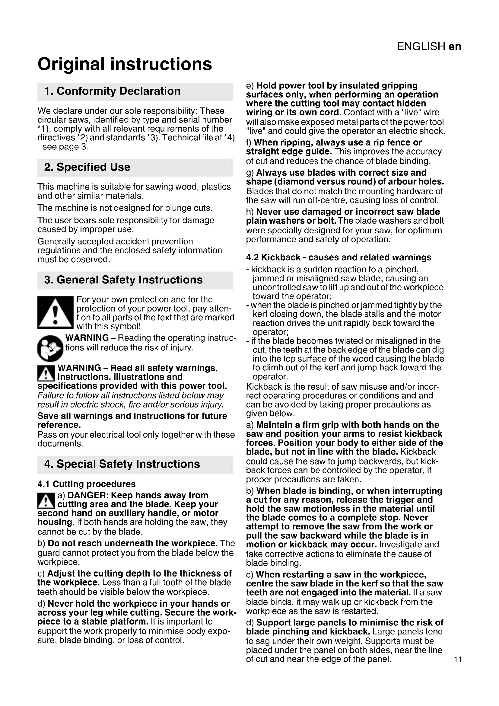
Original instructions We declare under our sole responsibility: These circular saws, identified by type and serial number *1), comply with all relevant requirements of the directives *2) and standards *3). Technical file at *4) - see page 3. This machine is suitable for sawing wood, plastics and other similar materials. The machine is not designed for plunge cuts. The user bears sole responsibility for damage caused by improper use. Generally accepted accident prevention regulations and the enclosed safety information must be observed. For your own protection and for the protection of your power tool, pay atten- tion to all parts of the text that are marked with this symbol! WARNING – Reading the operating instruc- tions will reduce the risk of injury. WARNING – Read all safety warnings, instructions, illustrations and specifications provided with this power tool. Failure to follow all instructions listed below may result in electric shock, fire and/or serious injury. Save all warnings and instructions for future reference. Pass on your electrical tool only together with these documents.
4.1 Cutting procedures
a) DANGER: Keep hands away from cutting area and the blade. Keep your second hand on auxiliary handle, or motor housing. If both hands are holding the saw, they cannot be cut by the blade. b) Do not reach underneath the workpiece. The guard cannot protect you from the blade below the workpiece. c) Adjust the cutting depth to the thickness of the workpiece. Less than a full tooth of the blade teeth should be visible below the workpiece. d) Never hold the workpiece in your hands or across your leg while cutting. Secure the work- piece to a stable platform. It is important to support the work properly to minimise body expo- sure, blade binding, or loss of control. e) Hold power tool by insulated gripping surfaces only, when performing an operation where the cutting tool may contact hidden wiring or its own cord. Contact with a "live" wire will also make exposed metal parts of the power tool "live" and could give the operator an electric shock. f) When ripping, always use a rip fence or straight edge guide. This improves the accuracy of cut and reduces the chance of blade binding. g) Always use blades with correct size and shape (diamond versus round) of arbour holes. Blades that do not match the mounting hardware of the saw will run off-centre, causing loss of control. h) Never use damaged or incorrect saw blade plain washers or bolt. The blade washers and bolt were specially designed for your saw, for optimum performance and safety of operation.
4.2 Kickback - causes and related warnings
- kickback is a sudden reaction to a pinched, jammed or misaligned saw blade, causing an uncontrolled saw to lift up and out of the workpiece toward the operator; - when the blade is pinched or jammed tightly by the kerf closing down, the blade stalls and the motor reaction drives the unit rapidly back toward the operator; - if the blade becomes twisted or misaligned in the cut, the teeth at the back edge of the blade can dig into the top surface of the wood causing the blade to climb out of the kerf and jump back toward the operator. Kickback is the result of saw misuse and/or incor- rect operating procedures or conditions and and can be avoided by taking proper precautions as given below. a) Maintain a firm grip with both hands on the saw and position your arms to resist kickback forces. Position your body to either side of the blade, but not in line with the blade. Kickback could cause the saw to jump backwards, but kick- back forces can be controlled by the operator, if proper precautions are taken. b) When blade is binding, or when interrupting a cut for any reason, release the trigger and hold the saw motionless in the material until the blade comes to a complete stop. Never attempt to remove the saw from the work or pull the saw backward while the blade is in motion or kickback may occur. Investigate and take corrective actions to eliminate the cause of blade binding. c) When restarting a saw in the workpiece, centre the saw blade in the kerf so that the saw teeth are not engaged into the material. If a saw blade binds, it may walk up or kickback from the workpiece as the saw is restarted. d) Support large panels to minimise the risk of blade pinching and kickback. Large panels tend to sag under their own weight. Supports must be placed under the panel on both sides, near the line of cut and near the edge of the panel.
3. General Safety Instructions
e) Do not use dull or damaged blades. Unsharp- ened or improperly set blades produce narrow kerf causing excessive friction, blade binding and kick- back. f) Blade depth and bevel adjusting locking levers must be tight and secure before making the cut. If blade adjustment shifts while cutting, it may cause binding and kickback. g) Use extra caution when sawing into existing walls or other blind areas. The protruding blade may cut objects that can cause kickback.
4.3 Lower guard function
a) Check the lower guard for proper closing before each use. Do not operate the saw if the lower guard does not move freely and close instantly. Never clamp or tie the lower guard into the open position. If the saw is accidentally dropped, the lower guard may be bent. Raise the lower guard with the retracting handle and make sure it moves freely and does not touch the blade or any other part, in all angles and depths of cut. b) Check the operation of the lower guard spring. If the guard and the spring are not oper- ating properly, they must be serviced before use. Lower guard may operate sluggishly due to damaged parts, gummy deposits, or a build-up of debris. c) The lower guard may be retracted manually only for special cuts, such as „plunge cuts“ and „compound cuts“. Raise the lower guard by the retracting handle (9) and as soon as the blade enters the material, the lower guard must be released. For all other sawing, the lower guard should operate automatically. d) Always observe that the lower guard is covering the blade before placing the saw down on bench or floor. An unprotected, coasting blade will cause the saw to walk backwards, cutting whatever is in its path. Be aware of the time it takes for the blade to stop after switch is released.
4.4 Additional safety instructions for all
saws with riving knife Riving knife function a) Use the appropriate saw blade for the riving knife. For the riving knife to function, the body of the blade must be thinner than the riving knife and the cutting width of the blade must be wider than the thickness of the riving knife. b) Adjust the riving knife as described in this instruction manual. Incorrect spacing, positioning and alignment can make the riving knife ineffective in preventing kickback. c) Always use the riving knife except when plunge cutting. The riving knife must be replaced after plunge cutting. The riving knife causes interference during plunge cutting and can create kickback. NOTE This warning is not applicable for plunge type saws with a spring loaded riving knife
d) For the riving knife to work, it must be engaged in the workpiece. The riving knife is ineffective in preventing kickback during short cuts. e) Do not operate the saw if riving knife is bent. Even a light interference can slow theclosing rate of a guard.
4.5 Additional Safety Instructions
OK or NG or N/A S723-EN_IEC62841-2-5-Rev00-140829 Page 6/40 e) Do not operate the saw if the riving knife is bent. Even a light interference can slow the closing rate of a guard Do not use grinding wheels. Pull the plug out of the plug socket before carrying out any adjustments or servicing. Keep hands away from the rotating tool! Remove chips and similar material only when the machine is at a standstill. Wear ear protectors. Wear protective goggles. Press the spindle locking button only when the motor is at a standstill. Do not reduce the speed of the saw blade by pressing on the sides. The movable safety guard must not be clamped in the pulled-back position for sawing. The movable safety guard must move freely, auto- matically, easily and exactly back into its end posi- tion. When sawing materials that generate large quanti- ties of dust, the machine must be cleaned regularly. Make sure that the safety appliances, e.g. the movable safety guard, are in perfect working order. Materials that generate dusts or vapours that may be harmful to health (e.g. asbestos) must not be processed. Check the workpiece for foreign bodies. When working, always make sure that no nails or other similar materials are being sawed into. If the saw blade blocks, turn the motor off immedi- ately. Do not try to saw extremely small workpieces. During machining, the workpiece must be firmly supported and secured against moving. Use a saw blade that is suitable for the material being sawn. Clean gummy or glue-contaminated saw blades. Contaminated saw blades cause increased friction, jamming of the saw blade and increase the risk of back-kicks. Avoid overheating of the saw tooth tips. Avoid melting of the material when sawing plastic. Use a saw blade that is suitable for the material being sawn.ENGLISH en
Reducing dust exposure: WARNING - Some dust created by power sanding, sawing, grinding, drilling, and other construction activities contains chemicals known to cause cancer, birth defects or other reproductive harm. Some examples of these chemicals are: - Lead from lead-based paints, - Crystalline silica from bricks and cement and other masonry products, and - Arsenic and chromium from chemically treated lumber. Your risk from these exposures varies, depending on how often you do this type of work. To reduce your exposure to these chemicals: work in a well ventilated area, and work with approved safety equipment, such as those dust masks that are specially designed to filter out microscopic particles. This also applies to dust from other materials such as some timber types (like oak or beech dust), metals, asbestos. Other known diseases are e.g. allergic reactions, respiratory diseases. Do not let dust enter the body. Observe the relevant guidelines and national regulations for your material, staff, application and place of application (e.g. occupational health and safety regulations, disposal). Collect the particles generated at the source, avoid deposits in the surrounding area. Use suitable accessories for special work. In this way, fewer particles enter the environment in an uncontrolled manner. Use a suitable extraction unit. Reduce dust exposure with the following measures: - do not direct the escaping particles and the exhaust air stream at yourself or nearby persons or on dust deposits, - use an extraction unit and/or air purifiers, - ensure good ventilation of the workplace and keep clean using a vacuum cleaner. Sweeping or blowing stirs up dust. - Vacuum or wash the protective clothing. Do not blow, beat or brush. See page 2. 1Guide plate 2 Adjusting screws for zero-play sliding on guide rail (guide rail not included in scope of delivery, see chapter on Accessories) 3 Locking screws (parallel stop) 4 Scale (diagonal cut angle) 5 Cutting indicator 6 Locking screws (diagonal cuts) 7 Parallel stop 8 Additional handle 9 Lever (for swivelling back the movable safety guard) * 10 Cable guide 11 Locking button (switching on) 12 Trigger (switching on and off) 13 Handle 14 Nozzle ( chip ejection) 15 Signal display * 16 Speed preselection wheel * 17 Hex screw (for splitting wedge setting) 18 Splitting wedge 19 Marking (saw blade outer diameter) 20 Inner saw blade flange 21 Movable safety guard 22 Saw blade 23 Outer saw blade flange 24 Saw blade fixing screw 25 Adjusting screw (adjust saw blade angle) 26 Lock nut (adjust saw blade angle) 27 Hexagon spanner 28 Locking screw ( for setting cutting depth
- Metabo S-automatic safety clutch: If the tool jams or catches, the power supply to the motor is restricted. Due to the strong force which can arise, always hold the machine with both hands using the handles provided, stand securely and concentrate.
- Mechanical safety brake for stopping saw blade quickly when switching off the machine (KSE 68 Plus only).
- Hard-wearing guide plate made from lightweight cast magnesium
- Vibration-damping, non-slip rubber coating in grip area.
- Double-guided parallel stop, can be used on the left and right for greater flexibility
- Lock preventing inadvertent machine start-up
- Lubricating system extends the service life of the gearbox
- Vario Tacho Constamatic (VTC) full-wave electronics for stepless speed adjustment. The machine speed stays constant automatically under load (only KSE 68 Plus)
- Setting wheel for speed preselection (only KSE 68 Plus)
- Electronic function monitoring the coil temperature protects against overload. Light signal when the machine begins to overload (only KSE 68 Plus)
- External dust extraction possible: option of connecting an extraction unit
- Carbon brushes for protecting the motor
- Guide rail available as an accessory (order no. 6.31213)
- Tool-less fine machine adjustment when used on guide rail 6.31213 Before plugging in, check to see that the rated mains voltage and mains frequency, as
7. Initial Operation, SettingENGLISHen
specified on the rating label, match your power supply. Pull the plug out of the plug socket before any adjustments or servicing are performed. Always install an RCD with a max. trip current of 30 mA upstream.
7.1 Setting splitting wedge
The splitting wedge (18) prevents the wood from closing behind the saw blade and jamming it while the machine is in operation. This could otherwise lead to recoiling. The splitting wedge must be set in such a way that the distance between its inner curve and the toothed ring on the saw blade is no greater than 5 mm. Set the splitting wedge so that the lowest point of the saw blade does not protrude by more than 5 mm below the bottom edge of the splitting wedge. See illustration on page 2. To adjust, loosen the hex screw (17), set the right distances to the saw disc and tighten the hex screw again.
7.2 Setting depth of cut
Loosen the locking screw (28). Raise or lower the motor section against the guide plate (1). Read the depth of cut that has been set from the scale (29). Tighten the locking (28)screw again. It is advisable to set the depth of cut in such a way that no more than half of each tooth on the saw blade juts out under the workpiece. See illustration on page 3. The clamping power of the locking screw (28) can be adjusted. Unscrew the screw on the lever to do this. Remove lever and mount offset anticlockwise. Secure with screw. When doing this, note that the cutting depth setting device moves freely when the lever is open.
7.3 Slanting saw blade for diagonal cuts
Loosen the two locking screws (6) to make the setting. Tilt the motor section against the guide plate. Read the angle which has been set from the scale (4). Retighten the front and then the rear locking screw (6).
7.4 Correcting the saw blade angle
The saw blade angle is set ex works. If, at 0°, the saw blade is not at right angles to the guide plate: release locking screws (6). Release lock nut (26) and correct saw blade angle with adjusting screw (25). Then retighten the lock nut. Retighten both locking screws (6).
7.5 Rotational speed preselection
Select the speed at the setting wheel (16). For recommended speeds, see page 2.
7.6 Extraction connection piece / dust
ejection The nozzle (14) can be rotated to the desired position to extract or eject chips. To do this, push the nozzle in up to the stop, turn and pull out again. The nozzle can be locked in 45° increments so that it cannot turn. Sawdust extraction: connect a suitable dust extraction unit with suction hose to the machine to extract the sawdust.
8.1 Switching on and off
Switching on: Press locking button (11) and hold in; then actuate the trigger (12). Switching off: Release the trigger (12).
8.2 Signal display (KSE 68 Plus)
The signal display (15) lights up briefly when the machine is switched on and indicates operational readiness. If the signal display lights up during operation, this indicates overloading. Reduce the load on the machine.
8.3 Working instructions
Lay out the mains cable such that the cut can be executed without obstruction. For this purpose, the mains cable can be held by the cable guide (10). The markings (19) are designed to help the user when positioning the machine and sawing the workpiece. In the case of maximum depth of cut, they mark approximately the outside diameter of the saw blade and thus the cutting area. Do not switch the machine on or off while the saw blade is touching the workpiece. Let the saw blade reach its full speed before making a cut. When the hand-held circular saw is added, the movable safety guard is swung backwards by the workpiece. KSE 68 Plus: the movable safety guard can be swung backwards manually using the lever (9) to make the machine easier to position on the workpiece. When sawing, never remove the machine from the material with the saw blade turning. Allow the saw blade to come to a standstill. If the saw blade blocks, turn the machine off immediately. Sawing along a straight line: the cutting indicator is used here (5). The width of the cutting indicator represents roughly the width of the saw disc. Sawing along a rail secured on the workpiece: In order to achieve an exact cutting edge, you can attach a rail to the workpiece and then guide the hand-held circular saw along this rail by means of the guide plate (1). Sawing with parallel stop: For cuts parallel to a straight edge. The double parallel stop (7) can be inserted from either side into the support provided for it. Maintain parallelism to the saw blade when making the setting. Retighten the front and then the rear
locking screw (3). It is best to calculate the exact cut width by making a test cut. For cuts parallel to a straight workpiece edge: Apply the parallel stop (7) such that the stop rail is facing down. For cuts parallel to a straight edge on the workpiece: Apply the parallel stop (7) such that the stop rail is facing up.
8.4 Sawing with guide rail 6.31213
For straight and splinter-free cutting edges accurate to the millimetre. The anti-slip coating keeps the surface safe and protects the workpiece against scratches. The machine can be placed against the stops on the guide rail for plunge cutting and cuts can be executed with a uniform length. For guide rail 6.31213, see chapter on Accessories. Depending on the application type and cutting width, the parallel stop (7) can be inserted from the right or left into its holder. Sawing very narrow sections: Insert the parallel stop (7) from the right into its holder. Clean the machine regularly. This includes vacuum cleaning the ventilation louvres on the motor. Use compressed air to clean the movable safety guard (21) regularly (wear safety glasses when doing so). The guard must move freely, auto- matically, easily and exactly back into its end posi- tion. Changing saw blades Pull the plug out of the plug socket before any adjustments or servicing are performed. - Press in the spindle locking button (30) and hold in place. Turn the saw spindle slowly with the spanner in the saw blade fixing screw (24) until the lock catches. - Remove the saw blade fixing screw (24) by turning it in counter-clockwise direction. - Remove the outer saw blade flange (23). Pull back the movable safety guard (21) and remove the saw blade. (22) - The contact areas between the inner saw blade flange (20), the saw blade (22), the outer saw blade flange (23) and the saw blade fixing screw (24) must be clean. For correct operation of the safety clutch, the contact surface of the saw blade fixing screw (24) that contacts the saw blade must be coated with a thin film of grease. Regrease with a multi-purpose grease (DIN 51825 - ME / HC 3/ 4 K -30). - Insert a new saw blade, making sure the direction of rotation is correct. The direction of rotation is indicated by arrows on the saw blade and safety guard. - Put on the outer saw blade flange (23). - Tighten the saw blade fixing screw (24). Use only sharp, undamaged saw blades. Do not use any cracked saw blades or blades that have changed their shape. Do not use any saw blades which have a thicker base body or a smaller width cut than the splitting wedge. Do not use any saw blades made from high- alloy high-speed steel (HSS). Do not use any saw blades which do not conform to the specified rating. The saw blade must be suitable for the no-load speed. Use a saw blade that is suitable for the material being sawn. Saw blades intended for cutting wood or similar materials have to conform to EN 847-1. Use only genuine Metabo accessories. Use only accessories that fulfil the requirements and specifications listed in these operating instruc- tions. For a complete range of accessories, see www.metabo.com or the main catalogue. Repairs to electrical tools must be carried out by qualified electricians ONLY! A defective mains cable must only be replaced with a special, original mains cable from metabo, which is available only from the Metabo service. If you have Metabo electrical tools that require repairs, please contact your Metabo service centre. For addresses see www.metabo.com. You can download spare parts lists from www.metabo.com. Observe national regulations on environmentally compatible disposal and on the recycling of disused machines, packaging and accessories. Only for EU countries: Never dispose of power tools in your household waste! In accordance with European Guideline 2012/ 19/EU on used electronic and electric equipment and its implementation in national legal systems, used power tools must be collected separately and handed in for environmentally compatible recycling. Explanatory notes on the specifications on page 3. Changes due to technological progress reserved.
45° =max. depth of cut (45°) A =Adjustable diagonal cut angle D =Saw blade diameter d =Saw blade drill diameter a =Max. base body thickness of saw blade b =Cutting width of saw blade c =Thickness of splitting wedge m=Weight Measured values determined in conformity with EN 62841. Machine in protection class II ~ Alternating current The technical specifications quoted are subject to tolerances (in compliance with the relevant valid standards). Emission values Using these values, you can estimate the emissions from this power tool and compare these with the values emitted by other power tools. The actual values may be higher or lower, depending on the particular application and the condition of the tool or power tool. In estimating the values, you should also include work breaks and periods of low use. Based on the estimated emission values, specify protective measures for the user - for example, any organisational steps that must be put in place. Vibration total value (vector sum of three directions) determined in accordance with EN 62841:
h,D =Uncertainty (vibration) Typical A-effective perceived sound levels:
= Sound pressure level
= Acoustic power level
= Uncertainty During operation the noise level can exceed 80 dB(A). Wear ear protectors!
- Energy-rich, high-frequency interference can cause fluctuations in speed. The fluctuations disappear, however, as soon as the interference fades away.FRANÇAIS fr