
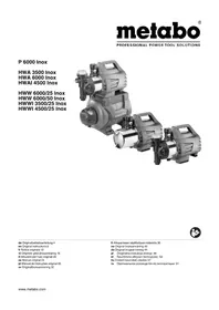
HWW 350025 Inox - Pump METABO - Free user manual and instructions
Find the device manual for free HWW 350025 Inox METABO in PDF.
| Product type | Surface pump for clear water |
| Brand | Metabo |
| Model | HWW 350025 Inox |
| Body material | Stainless steel |
| Power supply | 230 V / 50 Hz |
| Rated power | 800 W (estimated) |
| Tank volume | 25 L |
| Pre-charge pressure | 1.5 bar |
| Max. suction height | 8 m (estimated) |
| Max. delivery pressure | 6 bar (estimated) |
| Max. flow rate | 3500 L/h (estimated) |
| Max. fluid temperature | 35 °C |
| Protection rating | IPX4 |
| Dimensions (L x W x H) | 500 x 300 x 600 mm (estimated) |
| Weight | 18 kg (estimated) |
| Main functions | Self-priming, dry-run protection, pressure tank, pressure switch |
| Maintenance and cleaning | Regular cleaning of suction filter, drain in case of frost |
| Safety | 30 mA residual current device, thermal protection, automatic shutdown in case of fault |
| Spare parts and repairability | Repair by qualified personnel, parts available at www.metabo.com |
| General information | Domestic use, not suitable for drinking water |
Frequently Asked Questions - HWW 350025 Inox METABO
User questions about HWW 350025 Inox METABO
0 question about this device. Answer the ones you know or ask your own.
Ask a new question about this device
Download the instructions for your Pump in PDF format for free! Find your manual HWW 350025 Inox - METABO and take your electronic device back in hand. On this page are published all the documents necessary for the use of your device. HWW 350025 Inox by METABO.
USER MANUAL HWW 350025 Inox METABO
Sh,max =max.Saughohe
Original instructions
1. Declaration of Conformity
Under our sole responsibility, we hereby declare that these pumps/domestic water systems/automatic domestic water systems, identified by type and serial number 1 , comply with all relevant requirements of the directives 2 and standards 3 . Technical documents for 4 - see page 3.
2. Specified Use
This device is used for conveying clean water in the house and garden area, for sprinkling and watering, as a well pump, rain pump and domestic water pump and for pumping out swimming pools, garden ponds and water tanks.
The maximum permissible temperature of the conveyed medium is 35^
The device must not be used for drinking water supply or for conveying food supplies.
Explosive, combustible, aggressive or other substances that are harmful to health must not be conveyed.
The device is not suitable for commercial or industrial use.
This device is not designed for use by persons (including children) with limited physical, sensory or mental aptitude or lack of experience and/or knowledge.
Unauthorised modifications to the device and the use of parts that are not tested and approved by the manufacturer are prohibited.
All improper use of the device is regarded as nonspecified use; this can result in unpredictable damage! The user bears sole responsibility for any damage caused by improper use.
Generally accepted accident prevention regulations and the enclosed safety information must be observed.
3. General Safety Instructions

For your own protection and for the protection of your appliance, pay attention to all parts of the text that are marked with this symbol!

WARNING - Reading the operating instructions will reduce the risk of injury.

WARNING Read all safety warnings and instructions. Failure to follow all safety
warnings and instructions may result in electric shock, fire and/or serious injury.
Keep all safety instructions and information for future reference.
Pass on your pump only together with these documents.
Information in these operating instructions is categorised as shown below:

Danger! Risk of personal injury or environmental damage.

Risk of electric shock! Risk of personal injury by electric shock.

Caution! Risk of material damage
4. Special Safety Instructions
Children, adolescents and persons who are not familiar with the operating instructions must not use the device.
Children should be supervised to ensure that they do not play with the appliance.
When the pump is being used in swimming pools and garden ponds and in the protected areas around them, the provisions of DIN VDE 0100-702 and -738 must be observed.
The device must be supplied via a residual-current device (RCD) with a rated residual current of max. 30mA .
The device must not be used if there are persons in the water.
When used for domestic water supply, the statutory water and waste water specifications according to DIN 1988 must be observed.
The following residual risks essentially remain when operating pumps and pressure vessels cannot be fully eliminated (depending on features) - even if safety measures have been introduced.
4.1 Danger from the environment!
Do not expose device to rain. Do not operate device in a damp or wet environment.
Do not use the pump in hazardous areas or near inflammable liquids and gases!
4.2 Danger: Hot water!
Danger! Install a check valve at the suction connection (12) to prevent water from flowing back into the suction line. This can reduce the following danger:
Hot water can cause damage and leaks on the pump and the connection lines, allowing hot water to escape. Danger of scalding!
Devices with the designation HWW....: If the shut-off pressure of the pressure switch cannot be reached due to poor pressure conditions or a defective pressure switch, the water can heat up within the pump as a result of internal circulation.
Devices with the designation P.... Operate the pump a max. of 5 minutes against the closed discharge line. Water that circulates inside the device is heated up.
In the event of a fault, unplug the pump from the power-supply system and allow to cool. A specialist must check the system to make sure it is in perfect working order before it can be used again.
4.3 Danger! Risk of electric shock!
Never direct the water jet directly at the device or other electrical
components! Risk of fatal electric shock!
Prior to installation and maintenance tasks, always disconnect the device from the power-supply system.
Do not touch the plug with wet hands! To disconnect, always pull on the plug, not the power cable.
Do not buckle, squeeze, drag or drive over power cable or extension cables; protect from sharp edges, oil and heat.
4.4 Danger due to device deficiencies or malfunctions!
Before each use, check the device for possible damage - especially the mains cable, mains plug and electrical components. Risk of fatal electric shock!
A damaged device must only be reused after it has been correctly repaired.
Do not attempt to repair the pump yourself! Only specialists are permitted to repair pumps and pressure vessels (depending on features).
Caution! To prevent water damage, e.g. flooded rooms, caused by device malfunctions or deficiencies:
- Introduce suitable safety measures, e.g.: alarm system or collecting tank with monitor The manufacturer is not liable for any damage caused by:
-improper use of the pump;
-
overloading of the pump through continuous operation;
-
failure to operate and store the pump in a frost-free environment;
-
unauthorised modification of the pump (repairs to electrical equipment may only be carried out by qualified electricians!);
-
use of spare parts which have not been tested and approved by the manufacturer; or
-
use of unsuitable installation materials (fittings, connection lines etc.).
Suitable installation materials:
- pressure-resistant (min. 10 bar)
-heat-resistant (min. 100^)
When using universal swivel couplings (bayonet couplings), only use versions with an additional securing ring to ensure safe sealing.
5. Overview
See page 2. The illustrations serve as examples for all devices.
1 ON/OFF switch*
2 LED (Fault)
3 LED (ON, STANDBY, Info) *
4 Button (ON, OFF, or "Mode A", RESET) *
5 Control panel
6 P u m p
7 Pressure vessel
8 Air valve for pilot pressure
9 Water drain screw
0 Pressure switch
1 Pressure gauge (water pressure)
12 Suction connection
13 Water filling screw
14 Pressure connection
15 Key
16 Cover*
17 Filter unit
18 Cup
19 Filter
20 Check valve *
- depending on features
6. Initial Operation
6.1 Setting the pilot pressure
Set the pilot pressure before initial operation. See section 9.4.
6.2 Installation
The device must be positioned on a horizontal, flat surface that is suitable for the device weight with water filling.
To avoid vibrations, the device should not be bolted on but rather should be positioned on a resilient base.
The place of installation should be well ventilated and protected against weather influences. Protect against frost - see section 8.3.
For operation in garden ponds and swimming pools, the device must be installed in a flood-proof location and secured against falling in. Additional statutory requirements must be taken into consideration.
6.3 Connecting the suction line
Caution! The suction line must be installed such that no mechanical or twisting forces are exerted on the pump.
Caution! Use an intake filter to protect the pump against sand and contamination.
Caution! A check valve is absolutely necessary to prevent the water from draining when the pump is switched off. We recommend the installation of check valves at the intake opening of the suction hose and at the suction connection (12) of the pump. Depending on the model, a check valve may already be integrated (see section 13. Technical Specifications).
Seal all screw-couplings with thread sealing tape. Leaks result in air intake and reduce or prevent the water intake.
The suction line should have an inside diameter of at least 1^ (25 mm); it must be kink- and vacuum-resistant.
The suction line should be as short as possible because the longer the line length, the lower the conveying capacity.
The suction line should rise uniformly towards the pump to prevent air inclusions.
A sufficient water supply must be guaranteed and the end of the suction line should always be under water.
6.4 Connecting the discharge line
Caution! The discharge line must be installed such that no mechanical or twisting forces
are exerted on the pump.
Seal all screw-couplings with thread sealing tape to prevent water discharge.
All components of the discharge line must be pressure-resistant and installed correctly.
Danger! If non-pressure-resistant components are installed, or assembly is incorrect, the discharge line can burst during operation. Injuries are possible if highly pressurised fluids are ejected!
6.5 Connection to a pipe network
To reduce vibration and noises, the device should be connected with flexible hose lines to the pipe network.
6.6 Mains connection
Danger! Risk of electric shock! Never operate the device in a wet environment and only under the following conditions:
- Connect only to an earthed outlet that is properly installed, earthed and tested.
- Mains voltage, mains frequency and fuse protection must correspond to those stated in the 'Technical Specifications'.
- The device must be supplied via a residual-current device (RCD) with a rated residual current of max. 30mA .
- The electrical connections must not be under water and must be located in a flood-proof area. The connections must be splashproof for outdoor use.
- Extension cables must have sufficient conductor cross sections. Unroll cable reels fully.
- National installation specifications must be observed.
6.7 Filling the pump and suction
Caution! In the case of a new connection, water loss or air intake, the pump must be filled with water. Operation of the pump without water filling will destroy it!
- Unscrew water filling screw (13) including gasket.
- Slowly pour in clean water until the pump is filled.
- Screw in water filling screw (13) with gasket again.
- Open the discharge line (open water tap or spray nozzle) so that air can escape during suction.
- Switch on the device (see section 7.).
- When water emerges evenly, the device is ready for operation.
Note: The suction line does not need to be filled because the pump is self-priming. Depending on the length and diameter of the line, however, it may take some time until pressure is built up. To shorten the suction time: install a check valve at the intake opening of the suction hose and fill the suction line too.
7. Operation
Caution! The pump and suction line must be connected and filled (see section 6.).
Caution! The pump must not be allowed to run dry. There must always be sufficient conveying medium (water) available.
If the pump is blocked by foreign bodies or the motor is overheated, a protective circuit shuts down the motor.
7.1 Explanation of operating elements Devices with ON/OFF switch (see illustration A)
Use the switch (1) to turn the device on/off.
Devices with control panel (see illustration B)
For HWA....HWW...
Insert mains plug. The pump is ready for operation: The LED (3) lights up in blue (STANDBY).
Switching on:
To switch on, press the ON/OFF button (4) briefly. The pump motor starts to run and the LED (3) lights up in green.
Dry-running protection:
If the pump is unable to convey water after 20 seconds, the LED (3) starts to flash slowly in green.
If the pump is unable to convey water after a further 100 seconds, the pump motor stops for 5 seconds (the LED (3) starts to flash quickly in green), and tries to convey water for a further 2 cycles.
If the pump cannot still convey water, it stops and the LED (2) lights up in red (dry-running protection). Check that the end of the suction line is under water. Check if leaks are causing air intake and thus preventing water intake. Proceed as described below to put the pump into operation once again:
HWA..., HWW....: Press the button (4) and keep it pressed for 3 seconds (RESET).
P 6000 Inox: Disconnect the mains plug and insert once again.
When the pump is able to convey water, the LED (3) lights up in green and remains lit.
Switching off:
To switch off, press the ON/OFF button (4) briefly.
Pump shut-down when the discharge line is closed:
If the discharge line is closed when the pump is running, (close water tap or spray nozzle), the pump must switch off automatically. Otherwise, overheating or damage can occur or there may be a risk of scalding due to the heated water. The electronics check at regular intervals whether water is flowing through the pump.
HWW..., HWA....: If there is no water flow detected, the LED (3) flashes in green for 40/70 seconds. The pump motor then switches off and the LED (3) lights up in blue (STANDBY).
P 6000 Inox: If there is no water flow detected, the LED (3) flashes in green slowly for 20 seconds and then quickly for a further 5 seconds. The pump motor then switches off and the LED (3) lights up in red. To put the pump into operation once again: Disconnect the mains plug and insert once again.
Safety mechanism for insufficient flow volume: If the flow volume is insufficient (less than approx. 60 l/h, e.g. in the case of leaks), the pump switches on and off frequently. This can cause the pump to overheat or get damaged or the heated water may pose a scalding risk. If the pump tries to switch on off more than 6 times in 100 seconds, it is switched off for safety reasons and the LED (2) lights up in red. Eliminate the reason for this! To put the pump into operation once again: Disconnect the mains plug and insert once again.
7.2 Using the device
Pump
(device designation P...
Functional principle: The device operates while it is switched on.
Danger! P 4500 Inox: If the discharge line is closed, run the pump for a maximum of 5 minutes because otherwise overheating of the water in the pump can cause damage.
- Insert mains plug.
- Fill pump if necessary - see section 6.7.
- Switch on the device - see section 7.1).
- Open the discharge line (open water tap or spray nozzle).
- Check that water emerges!
- When work is complete, turn off the device - see section 7.1.
Only for P 6000 Inox: A switch to "Mode A" is necessary if the pump is to be activated via an attachment unit (e.g. Hydromat (order no. 0903063238), timer). To do this, insert the mains plug and press the button (4) for more than 3 seconds. The LED (3) changes from green to blue. The pump can now be unplugged and connected to the attachment unit.
To return to "normal mode", insert the mains plug and press the button (4) for more than 3 seconds. The LED (3) changes from blue to green.
ENGLISHen
The pump can be switched on/off in "Mode A" using the button (4) also. Dry-running protection is also the same as in normal mode.
Automatic domestic water system (device designation HWA...)
Functional principle: The device switches on when the removal of water causes the water pressure to fall below the switch-on pressure; it switches off again when switch-off pressure is reached.
- Insert mains plug.
- Fill pump if necessary - see section .6.7
- Switch on the device - see section 7.1).
- Open the discharge line (open water tap or spray nozzle).
- Check that water emerges! The device is now ready for operation.
Domestic water system (device designation HWW...)
Functional principle: The device switches on when the removal of water causes the water pressure to fall below the switch-on pressure; it switches off again when switch-off pressure is reached. The pressure vessel contains a rubber bellows, which is under air pressure (pilot pressure) when delivered; this permits the removal of small volumes of water without the pump starting up.
- Insert mains plug.
- Fill pump if necessary - see section 6.7.
- Switch on the device - see section 7.1).
- Open the discharge line (open water tap or spray nozzle).
- Check that water emerges! The device is now ready for operation.
8. Maintenance

Danger! Prior to all servicing:
-Unplug mains cable
- Ensure that the device and connected accessories are depressurised.
- Repair and maintenance work other than described in this section should only be carried out by qualified specialists.
8.1 Regular maintenance
- Check device and accessories, in particular, electrical and pressurised components, for damage and repair if necessary.
- Check suction and discharge lines for leaks.
- If the conveying capacity decreases, clean intake filter and filter element (if installed) and replace if necessary. - Replace shaft seal. See section 11.
- Check the pilot pressure of the pressure vessel (7) (depending on features) and increase it if necessary (see section 9.4 Increasing pilot pressure).
- Check valve (accessories) blocked.
- Clean, replace if necessary.
- Water discharge between motor and pump, shaft seal leaking. (Minor discharge of water (max. approx. 30 drops per day) is normal with the use of shaft seals).
- Replace shaft seal. See section 11.
- Pump clogged or defective.
Se e s c t i o n 9.1 .
8.2 Cleaning the intake filter (depending on features)
- Unscrew the cover (16) (using the key if necessary (15)).
- Pull the filter unit (17) upwards vertically to remove.
- Disassemble the filter unit: Hold the cup (18), turn the filter (19) in a clockwise direction and remove it from the cup (bayonet lock).
- Place the cup (18) under flowing water to clean and use a soft brush to clean the filter (19).
- Assemble again in reverse order. In doing so, ensure that the filter unit (17) is fully inserted.
8.3 Danger of frost
Caution! Frost (< 4 °C) destroys the pump and accessories as both always contain water!
- If there is a danger of frost, disassemble pump and accessories and store in frost-free conditions (see following section).
8.4 Removing and storing device
- Switch off appliance. Unplug mains cable.
- Open the discharge line (open water tap or spray nozzle), allow water to drain off completely.
- Completely drain the pump (6) and vessel (7) by:
- unscrewing the water drain screw (9).
- Remove suction and discharge lines from device.
- Store device in a frost-free room (min. 5^ ).
9. Troubleshooting

Danger!
- Prior to all servicing:
- Unplug mains cable.
- Ensure that the device and connected accessories are depressurised.
9.1 Pump is not running
- No mains voltage.
- Check on/off switch, cables, plug, socket and mains fuse.
- Mains voltage too low.
- Use an extension cable with sufficient conductor diameter.
- Motor overheated; motor protection relay tripped.
- After cooling the pump will switch on again.
- Guarantee sufficient ventilation, keep air slots free.
- Observe maximum supply temperature.
- Motor hums, but does not start.
- With the motor switched off, insert a screwdriver or similar object through the air slots on the motor and turn the fan impeller.
- Pump clogged or defective.
- Disassemble and clean pump. Clean diffuser, replace if necessary. Clean impeller, replace if necessary. See section 11.
9.2 Pump not drawing in correctly or running very loudly:
Insufficient water.
- Ensure there is a sufficient water supply.
- Pump not sufficiently filled with water.
- S e e s e c t i o n 6 . 7 .
Suction line leaking.
- Seal suction line, tighten screw-couplings.
- Suction height too high.
- Observe maximum suction height.
- Insert check valve, fill suction line with water.
- Intake filter (accessories) obstructed.
- Clean, replace if necessary
9.3 Pressure too low or pump runs continuously:
- Suction line leaking or suction height too high.
- Se e s c t i o n 9 . 2 .
- Pump clogged or defective.
Se e s c t i o n 9.1.
- HWW...: Pressure switch incorrectly adjusted.
- Read off switch-on and switch-off pressure at the pressure gauge (11) and check values (see section 13 Technical Specifications). If an adjustment is necessary, please contact Metabo Customer Service. See section 11.
- HWW... Pump starts up even after removal of small volume of water (approx. 0.5 l).
- Check whether the pilot pressure in the pressure vessel is too low. Increase pressure if necessary. See section 9.4.
- HWW...: Water is running out of the air valve.
- Rubber bellows in pressure vessel leaking, replace it. See section 11.
P 6000 Inox: The LED (3) lights up in blue. - "Mode A" is enabled. See section 7.2
9.4 Increasing pilot pressure (only HWW...)
If - in the course of time - the pump starts up even after the removal of a small volume of water (approx. 0.5 l), the pilot pressure in the vessel must be restored.
Note: The pilot pressure cannot be read off at the pressure gauge (11).
- Unplug mains cable.
- Open the discharge line (open water tap or
spray nozzle), allow water to drain off completely.
- Unscrew plastic cap on front face of pressure vessel; the air valve is located behind it.
- Mount air pump or compressor hose with a "tyre valve" connection and pressure gauge on the air valve.
- Pump up to the specified pilot pressure (see section 13. Technical Specifications).
- Connect device again and check operation.
10. Accessories
Use only genuine Metabo accessories.
Use only accessories that fulfil the requirements and specifications listed in these operating instructions.
For a complete range of accessories, see www.metabo.com or the catalogue.
11. Repairs
Danger! Repairs to this device must be carried out by qualified electricians only!
If you have Metabo devices that require repairs, please contact your Metabo service centre. For addresses see www.metabo.com.
For shipment: drain pump and vessel completely (see section 8.4).
You can download spare parts lists from www.metabo.com.
12. Environmental Protection
Observe national regulations on environmentally compatible disposal and on the recycling of disused machines, packaging and accessories.
Only for EU countries: Never dispose of power tools in your household waste! In accordance with European Guideline 2002/96/EC on used electronic and electric equipment and its implementation in national legal systems, used power tools must be collected separately and handed in for environmentally compatible recycling.
13. Technical Specifications
Explanatory notes on the specifications on page 3. Subject to change in line with technological advances.
The pump characteristic curve (diagram on page 3) shows the conveying capacity that can be reached depending on the conveying height (suction height 0.5m and 1^ suction hose).
V = Check valve (20) integrated at pump suction connection (12)
K = Mains connection lead
U = M a i n s
f =Frequency
P1 =Rated power
= Rated current
C =Operating condenser
n =Rated speed
F_V, = Max. conveying capacity
F_h, = Max. conveying height
Fp,max =Max. conveying pressure
p1 =Pressure switch: switch-on pressure
p2 =Pressure switch: switch-off pressure
Sh,max^ = Max suction height
Stemp = Max. supply temperature
T_temp = Ambient temperature
S_1 =Splash protection class
S2 =Protection class
S_3^- =Insulation class
M=Pump housing material
M =Pump shaft material
M_W = Pump impeller material
Ds =Suction connection female thread
D_p =Pressure connection female thread
T =Pressure vessel volume
Tp,max =Max. vessel pressure
Tp.1 =Vessel pilot pressure
A=Dimensions:
Length x Width x Height
m =Weight (with mains cable)
Alternating current
The technical specifications quoted are subject to tolerances (in compliance with the relevant valid standards).

Emission values
Using these values, you can estimate the emissions from this power tool and compare these with the values emitted by other power tools. The actual values may be higher or lower, depending on the particular application and the condition of the accessory or power tool. In estimating the values, you should also include work breaks and periods of low use. Based on the estimated emission values, specify protective measures for the user - for example, any organisational steps that must be put in place.
Typical A-effective perceived sound levels:
LpA =Sound pressure level
LA =Acousticepowerlevel
K_pA, K_WA = Uncertainty
L_WA(G) =Guaranteed acoustic power level as per 2000/14/EC


Wear ear protectors!
4 Toets (ON, OFF, EVT. ,Mode A", Reset) *
Pompverstoft of defect.
- Pomp demonteren en reinigen. Diffusor reinigen, eventuel vernieuwen. Loopwiel reinigen, eventuel vernieuwen. Zie hoofstuk 11.
4 Tasto (ON, OFF, eventually "Mode A", RESET) *
S_temp = temperature at effusso max.
Ttemp =temperatura ambiente
3 LED (ON, STANDBY, Info) *
4 Painike (ON, OFF, tarv. "Mode A", RESET) *
5 Ohjiaustaulu
6 Pumppu
Ttemp =ympariston lampotila
S1=roisksuojaluokka
S2 =suojaluokka
3 LED (ON, STANDBY, Info)
4 Knap (ON, OFF,evt. "Mode A", RESET) *
5 Betjeningspanel
6 P u m p e
Reservedelslicer kan downloads paa www.metabo.com.
12. Miljobeskytelse
F p,max =Maks. pumpetryk
p1 =Pressstat:tilkoblingstryk
p2 =Pressostat:frakoblingstryk
S_h, = Maks.sugehjde
Stemp =Maks.tillobstemperatur
Ttemp =Omgivende temperatur
ElambdaeTe To diakontn evpyoioinoc/ anevpyoioinoc (On/Off), to KaAwoio, to ,TnV npclKa TnV aofAia.
-Nou xqunn raon pEuμatoc.
-XpnooioieTkeAkwiaikn npoeKtaon Etapkouc biatounc kawvov.
Ynephepaavon kivntnpa, evepyonoinon tns diataEns npoostaoiaoc Tou kivntnpa.
Meta tvy uoukeun tietai kai nauutoata oe aeitoupyia.
Φovtiote yia enapkn aepioo, kpatnoTe euethetapec tic oxuues aepioou.
- PoooeTe Tn Meyiotn 0epuokpaia npoa-ywns.
- O kivtnpac bouic, aaladev Ekvia.
Me anepeyotounevo tov kivtnnpa nepaoet eva kataoi ni kati npapoioo eana aio tic oxiaueaeipiaou tou kivtnpaa kai yupiote tn dtpewthou aeuiotnpa. - AvTia paayuev n eAattwuaatikn.
AnouvapuooynteKaKathetaTe Tny avTia. Kaqpiote to daiuxtn, evxoeewoc avikataoTnote Tov. Kaqpiote Tn eWt,Evxoeuwc avtkataoTnote Tny.BeNE oTo kepaiaio 11.
EAAHNIKAeI
9.2 Havlia avappo 工 ootoupyei napa nou opufo:
Eλειηνερού.
Bεβαιωθειτεότι Μιὰρχει διθέσιμο επαρκες πάθεμανερου.
Havlaia devivalapkeetayeutmvepó.
-BaEπεστοκεφαλαιo6.7.
Mn oteyavoc oWlambdaac avappofoons
Στεγανοποιητε το σωληνα αναρρόφησης, σφιξετις κοχλιούνδεσεις (pακόρ).
Yyocavappofo nno nlo u yalo.
- PooeEto ueyioTo uoc avappoOnc.
TooTheTnBaaBiaaventniotpohnc, yeiote to oawna avappofoanc me vepo.
- IaTpo avappofo nC (EApntma) ppauevo.
KaBapioTe Tnv,EvdeltaovucavTKata- Otnote Tnv.
BaIbIaavTeuotpohnc (EApntma) mIoKa-piouevn.
KaBapioTe Tny, evdexouevwacvtikata-otnote Tny.
- Diappo n vpou eTaE kivnTnpa kaiavTlac, oTeyavotoinδakTuiou olaOthonc un oTeyavn. (Mia oJnuantin diappo vepou (to oIou npitou 30 otayovec tnv nuepa) uPhiaviεTea onv npitptwn oTeyavotoinδakTuiou oiaOthonc loyow aetoupyiac).
-Avtikataotntote n oteyavonoinn daKTu- liou olaogns. BLENE OTO kepaalio 11.
- AvTia paayevn n eAattwataikn.
Béπε ΘO KεφáλαI 9.1.
9.3 Iieo noluxaunn n avtla aetoupyei ouvexwc:
- avappofoqno n un oTeyavoc n uos avappofoq no n oA u eya.
BλεπσTOκεΦαλαI09.2. - AvTia paayevn n eAattuataikn
-BaeneoKeΦaiaio9.1. - HWW....: Diakottnnc TIEoNc anoppuOmuEvoc.
Aiaaote nvi nieon evpyooinnc kai nvi nieon anevepyooinc oTo mavouetpo (11) KAI EeyETC TIC TIEC (BAEI OTO KEPAALIO 13. Teyivka oToxiela). Se nepintwn Juaas atapaitnnc npoapuoyns aneuvvheite napakaaw otuunja eEumptpnns peatw vmc Metabo.Baene oTo KEPAALIO 11.
HWW....HavTAlaEeKivá nδn μεταπo μikpλημν ερού (περισου 0,5λιτρa).
EaYETe, EAV nieon npoannpoc oTo λεβηta elva trou xamn. Evexouevco auEnote tvv. BλeTe okeφαλio 9.4. - HWW...: Tpexενερο ano τη βαλβδα ερα.
AaotixEvia pooka sto IeBnTa un Tevavn, avtakataoThe nV. BAne oKepaalio 11.
P 6000 Inox: H LED (3) avaee
H"AEioupyiaA\vivaievepyoioinuevN. Bλεπeσoκεραλaio7.2
9.4 Auxon ts nieoic npoanpwo (movo HWW...)
O'atv- me thnpado tou xovou-n avtia
Eekiva nJn eT aio mua iukn Ayn vepou (neipotu 0.51tpa, npTei va atokataTaThei
Eava nieon npontnwnoc sto Aebnta.
YnOeEiEn: H iieon npontpnpoNc 6ev μtopei va δiaβaσtei στο μavóμετρo (11).
- TpaBnEte to fic ano tny npia.
- AvoIeTe To oUImNa kataOthuIync (avoIeTe Tn Bava vepou n To akpofoio tsekaoou) afoTeTo vepo va xubei ETVeLwC
- 三βδωτεTOλaσικό τομα ση μετωικό Μλευρά του λέβητα, από πιω βριοκεται η Μαλβδα του εαρα.
- TOnoBtOte mV avTla aepa nToV eka-muTTO oWlva ToU ouMtuOeTN ME mua ovvEoN Eλaotikou' KAI ToavouEePo NaW Otn BαβIδa Tou aepa.
5.AtOKATAOTNE TNY PPOBAENTOJEV NIEON pONANPOWNC (BAEEN ETO KEAa1o 13. TeYvika oToxieia). - Suvodote EaV aTn ouokun kai eEyEe Tn λειουργia.
10. Eεapτηματa
XpoiooieTe movo yvnoia Eaaptmuata Tc Metabo.
XpnoiOnoiTe Moyo EApntmuata, ta onoia
IAnpovu Tc anaimoeic kai ta Xapaktnpiotka
Otoxela nou avapepovtai oe autec tic obnyie
Aletoupyiac.
Pnpe npoypa ma EaopntmuatwBaene www.metabo.com n otov kaTaloyo.
11. Entokevn
Kivduoc! Oeuakeuec ae autn tu oukeun eitptentai vaekTovtai mvo ant oNktopeXvitec!
Tia tiookeuEc Metabo nou exouv avaykn
Etiokeunc anteouvveIte napakaaw otyn vnti
atoxn avtippownia tnc Metabo. Aieuovoeic
beta www.metabo.com.
Tia nV aiooToaH: Aebiaote evteawc TnV avTla kai to aeBetaT (beta oTO kepaiao 8.4).
Tous kataaoyous avtaalaktkwv mtopeite va tous katebaoet eon dieuuvon www.metabo.com.
12. PpOToaia nepiBaAovTOc
Tnpite Touc evoikouc kavoviaouc yia tvn aotoupan ouofova me touc kavovec npootaiaoc toupiadaiovtoc kalv avakukwon twv axpnootew epaaleiw, oukeuaowkai Eapntmuatuw.

Móvo yia TIC xwpeC TcE: Mny nTATE Ta nλεκτρικα εpyaλεia στοικια
aotoppmuata! Suubovmae Tyn Eupwtaikn Odbnyia 2002/96/EK nepi nEktpiuvkai nEktpvikuwovokewvKai TynEvovawatomTcOTo Ekvokdelta, Ta nEktpikaepyaleia npertevaoulambdaovtaiExwpioTaKai va eIiTpefoVvta iya avakukawon Me tpofoAiko troos toepiBaaov.
13. Tevxika oToixia
Aieukpivioeic oxetikα με ta otoixia on Σελδa 3.
Aiaipoumu to dikaiwma yia aalayec, nov Eumnpetouv tvn texviKn npoo.
H xapakntpiotk kauuun mcavtiaac (diayaamu, eai0a 3) delxvei, noia nodotnta eetadopac uypou niopei va niteuuxei avaloya e to uoc avtannc (uoc aavappoohcn 0.5m kalukantos oawvnc avappoohns 1"
V =Baβiδaavτεισροφης (20) ενωματωμενη στη συνδεση αναρροφησης
(12) ts avTlaq
K =KaIomega ouvdeltao nC OTo dikTuou deuataoc
U Taon dikTuou
f = 2uXvOToTnTa
P1 =Ovopaotiknloxus
=Ovoaatakn eVTaon pεμatos
C = Nukvwtnc λειτουργiaq
n =Ovoaataikoc apioooc oTpofo
Fy,max =Mey.μetaepoepvnoootnta
Fh,max =Mey. uos avTAnons
Fp,max =Mεγ.πεση αντΑησης
p1 = iakotntnc tiEoN: NieoN evepyortoi-noc
p2 =Aikontnns nies: nieon anevepyonol
non
Sh,max =Mεγ.νψος αναρροφησς
Stemp =Mεγ. θερμokpασι προσαγωης
Itemp =Oερμokpασιαπερβaλλovτος
S1 =Kattynopia npooTaoiac evavti yekaaou
S2 =Katnyopia npoostadiac
S3 =KaTnyopia movwtkoU aikoU
M=Yλioktou nepβλμatoc ts avλiag
M=Yλiokotouaovatavtia
MW =Yλικό της φτερωτής της αντλίας
D =EomegaKoTepiOaOuVseOnc avap- o0dnonc
D =EowTepiok otnipomega ouvdelta nieons
TV =OyKoC λεβητa
Tp,max =Mey. nieonn
T.1 =Niεη nponλnpωσns λεβnta
A 1aσταεις
MnKoc x IaToc x YUOC
m =Bapoc (με καλωδio σύνδεοης στορεύμα)
Evaλaσσóενo pεúα
Ta avaepojeva texvika otoxieia evvoovutai me avoxc (oumuva me tic kdoTote ixououc e texvike npodiaypapec).
Tiuéç eKnoumnc
Autec ot iuec kaotouv duavat nTv ktiunon twkntwnv tv nkeptikou epyaieou kai nuykpiomiafapown nektipkiuv epaewiiv Avaloayu e TIC ouvthekec epyaioac, TV kataotaon tov nkeptikou epyaeiou nTw EApntmuw unpoei to npayutko foptio va elvuaNtopeo xamIoTe. Tm nktiunon laBete unoi ta dalemuata epyaiaic kai tic paoeic mikoou pfotiou. Me daon icvtiaotoics ppoapoouec tioc ktiunons kaobopite metpa npootaoiac yia To xnoTn, P.x. opyawuktae peta.
Tunikec nxntikc oTaOe, aEioIoynon A:
LpA =∑taθμnηxntiknsieo
LWA =∑rαθμn nxtiknsxuos
KpA, KwA = Avaσφaλεια
LwA(G) =EyyunmuevnσaθμnnxntkncisoxoosuΦwva μεtnv oδηyia 2000/14/EK

Xpnoiopoiite npootaoia akonc (wtoaonii6c)!
Heo6xOIMO co6IIOaTb 60eIpnHraTbe npabnla TeXnIKn 630NaCHocTn, a TaHOke yKa3aHHn, npHaIraemble K daHHOMy pyKOBODCTBy.
3. 06uhe yka3aHnno TeHHKe 6e3onacHOCTn

ДЯВаewe co6ctBeeHHO6e3oNa-CHOCTN 3aAHTbI yCTPOCTBAOTOBpeKdHcN COJIIOdaTe YKa3AHn,OTMEeHHbIe DaHbIM CmBOMJ!

PNEyPNeKdEHNE!IJIaCHKeHnI RnCKaTpaMIMoBAnHnIPOuHTHe pyKOBoJCTBO NkCnPLnyatauN.
PNEpyPENHEHIE!IpoHTte Bce HNCTpyKnnu N yka3aHnno TexHHne 6e3oNaChOCTn. HeBbIIOJIHeHnE NHCtpyKnnu N yka3aHnno TEOxHHne 6e3oNaChOCTn MOKeT pINBeCTn K IopaeHnO 3IeHTPNeCHNt TKOM, BO3rOpaaHIO NIIIN K NOJyueHnO TArKeIbIX TpaBM.
CoxpaHnte BCE HNCTpyKcunn yHa3aHna No texHNke 6e30NaCHOCTn.
DablneupeaBaueroHacococ OcuyeCTBnTE TOIbKO BmecTe C3TUMN DOHy-MENTAM.
Hhopmaunna 063aehaB daHHOM pyKOBODCTBE NO hCnnyatauIN CneDyUOUM opa3OM:
Anachoctb!IpeDynpexdEHN6 OnachOCTn TpaBmipOBaHIN NIN BpeDeNOKpyKaiooie CpeDb.
Onachoctb noJyehn TpaBM BcneCTBne yda3JeHTPnechm TOKOM!IpeDyprEJaHHeN6 OAnochcto TpaMPOBaHN npna paOBeT cJIEKTpoooBopyoHaHem.

BHHaHHe!IpeDyIpEeJdeHne o B03MOKHO MATEpHaNbHOM yuepe6.
4. CneuNaIbHbIe yKa3aHnno texHnke 6e3oNaCHOCTn
He pa3pewaeTcNcNoIb3OBAHnE yCTpOeCTBa DeTbMn NOpPOCTkAMn, a TaKHe IuCaMn, He O3HaKOMNBWHmncr C pyKOBoDCTBOM NO 3KcNlyaTaun.
TeHdoJIHHbI HaxOHTbcra NOI NOCTOHHbIM Ha6JIODeHNEM, YTObI OHn He IcNoJIb3OBaJIY cTPOiCTBO B KaueCTBe HrpyuKn.
PnEKnIyatauB6accenHax npydaxdoJHHbco6IouaTbcn noJKeHn DIN VDE 0100-702, -738.
Питане устюсва должно OCUшecTBЯТьСС ПOMОцьЮ ABTOMATA 3auntbI OT TOKа yTeчк (RCD) c yctahOBJIeHHbIM TOKOM yTeчк MaHC.30 mA.
He pa3pe7aetc nCNoIb3OBAHnE yCTpoIcTba,ecIn B BoDe HaxoJATcJIIOuN.
Pn3KcNpyatauINBDOMaHHe CNCTeMe BOOCha6KeHnI DOJIHHbI CO6JIHOdaTbcra 3aKpe- PIIeHHbIe 3aKOHOM PpeDnIcaHn I OTHOCHTeJIbHO BOOCha6KeHnI BOOOtBeHnI, a TaKHe nIoJKeHnI DIN 1988.
Pn EKnIyatauHn HAcocOB n HaOpNbIX pe3epByapOB (B 3aBN-CMOCTN OT KOMNLeKTAuIN) CyueCTbYOT CJeDyUoJne OCTaTOOHbIE ONaCHOCTN, KOtOpbie HeJIb3r POJIHOCTbIO yCTpaHHTb, DaHe npINHB NaJIeKaUne MEPbl6e3ONaCHOCTN.
4.1 OnachocTb, CB3aHHa c OkpykaIOUe CpeoI!
He octabJnTe yctpoiCTBO nOddoKdem.He nCnoJIb3yIte yCTPOICTBO BO BlaHHbIX N cbIpBX IOMeUeHnX.
He nCnoIb3yIte yCTpoIcTBO BO B3pbIBOONaChbIX NOMEUeHnX INN B6NI3n FOpIOuNX KNDKOCTe INN rA3OB!
4.2 OnacHo - ropyaB Oda!
OnachOCTb! UcTaHOBnTe
6bpaTHbI KlaanH Ha BCaCbIBAIOUe NaTppy6Ke(12),UTo6bHe
DOnyCTNTb 6bpaTHOrO OTTOKa
BObl BO BCaCbIBaIOUe JINHH.
3TO NO3BOJNT UMeHbWHTb CLeNyIOUne OnaCHOCTN:
Bpe3yIbTaTe BO3eInCTBnR ropAeN BOdbIOrYT BO3HNKHyTb IOBpeJdeHnI Hn HeepMeTn-
HOCTb yCTpoCTBa H COeHNH-TeIbHbIX Tpy6OpPBODoB, Bpe3yIbTaTe Yero TropaB Oda MoKeT NoCTynaTb HapxKy. OnaCHOCTb OHora!
YcTpoiCTBa c 6o03HaueHnem HWW....: Ecln daBleHne OTHIOU-eyHna MaHOMeTpNecKO BbIKIooYaTeJI He DoCTnraeTCB BCJeCDTBHe HekOppeKTHO BblONHeHHbIX HaCTpoEkn BcIeDCTBne DeΦeKTa CamOro MaHOMeTpNecKO BblIIOuTaJI, BODa B pe3yJbTaTe BHyTpENHe nPpKylAunn BHyTpN YcTPOICTBa MoKeT HarpeBaTbcr.
YcTpoiCTBa C 6o3HaueHnEm P... npoDJIKNTeIbHocTb 3KcNlyatauyn yCtpoiCTBa npn 3aKpbITOn HAnOpHOJ LInHn He DoJIkHa npeBbIaTb 5 MInHyT. Boda, uPkyIpyOuaB HByTpni yCtpoiCTBa,HarpeBaeTcra.
B clyae Bo3HKnHOBeHn HEnCnpaBHOCHTN OTCOeHNHTe yCTpOJCTBO OT 3JeKtpnueCKoI CETn I DaITe EMy OCTbITb. Npeed NOBTOPbIM BBODOM B 3KcNlyaTaUIO CNEuHaNtCbI DOJHKbl PObEPNTb NCpapBHOCTh fYHKUHNPOBaHn YCTaHOBKn.
4.3 OnacHo - эльктучесТо!
He HanpaBnIe CtpyIO BODbl HeNocpeDCTBeHHo Ha yCTpOi-CTBO HnI DpyrHe 3JIeKTPnueckHne y3bl! OnacHO IJRA Jn3HN - BO3MOxHo IopaHexHne 3JIeKTPnueckHM TOkOM!
He donyckaetc npoBeHne pa60 nO yCTaHOBKe nTexHnueckomy 06CnyKHBAnu yCTpOnCTBa, NOkJIIOyeHHOrO K 3JIeKTPnueCKoI cTeN.
He 6epntecb 3a ceTeByIO BnIky BnaJHHbIMn pykam! Bcerda TAHNTe 3a ceTeByIO BnIKy, a He 3a Ka6ejb.
He donyckaIte 3aJOMOB, 3aHIMaHnHa Hae3da Ha CeTeBOH uDInHHTeBHyi Ka6eJIb; 6peRHTe OT KOHTaC OCTpbIMN KpOMKaMn, MaCLOM N BO3dEiCTBnA BbICOKHX TempePaTyP.
4.4 OnachocTb BCJeIcTBnE deΦeKToB HnHn HenCnpaB-HoCTeYcTPOIcTBA!
PpOBePnTe yCTpoNCTBO,BOCo-6eHHocTH CTeBoN KaBJIb, WTeKep N 3JIeKTpnueckNe DeTaJIH NaHaJIuHne NOBpeJdHNI nepeD
PYCCHNIRu
KaHdbIM BkIIOyeHnEM. OnaCHO IJN3HN - BO3MOXHO nopaHe Hne 3JIeKTPnuecknM TOKOM!
IOBTOPHOE HcnoJIb3OBAHHe NOBpeKdEHHOro yCTpoiCtBa dOnyckaeTcra TOLbKO NocLe Ocyu- ceTBJeHnpeMOHTa KBaIINΦuI npOBaHHbIMn CneUHaJIncTamn. He ocuyeCTBJaIte camocToIeJbHbI peMOHT yCTpoiCtBa! PpOBeDeHne pEmoHTa HacocOB n HanOpHbIX pe3epByapOB (B 3aBnCmOCTn OT KOMJIeKTaUIN) pa3peWaeTcra TOLbKO KBaIINΦuInpoBAHHbIMn CneUHaJIncTAmn.
BnHMaHne!Bo n36eKaHne yuepe6aOT BoDbl,HaNPmep 3aToJIeHnI NOMEuEHN, Bbl3- BaHHoro DeΦeKtAmN IIN HeNcnpaBHOCTAMN ycTePOiCTBa:
-3anlaHpyTe HaJIeKaUne MepbI 6e3ONaCHOCTN, HAnpIMep yCTPOJCTBO aBapnHOH cHrHaJIIN3aUNn IIN npMeHMbI pe3epByap CfYHKcNei KOHTPOJl POn3BOJNTeJIb He HeCET NkA-KoI OTBETCTBeHHOCTH 3a yUeP6, KOTOpbIMoKET 6bITb HaHeceH Bpe3yJbTaTe
-ИСПОЛБЗOBAHЯ yCTpoIcTBA He NO Ha3HaueHIO;
-Nepepy3Hn BCJIeDCTBHe HeIpePbIBHOI pa60TbI;
-3KcIyataunn nn XpaHeHna yCTpOJCTBa 6e3 3auntbI OT MOp03a;
- CAMOCTOReTbHOro BHeceHnI3MeHEnB KOHCTpyKcNIOyCTPOINCTBa; Ipon3BOAnITbpeMOHT 3JeKTpOpnp6OpOB pa3peShaETcToIbKO CneuaJIInCTAm-3JeKTpnKaM!
-NCNOLb3OBaHHa3aNaCHbIX YacTeH,He npoBepeHHbIX H He yTBepKdEHHbIX npOn3BODnTeJEM;
-NCNoB3OBAHnHeNoXoJa 1IeRO MOnTaXHO MaTePnaIa apMaTpy,coeHNHTeNbHbIe Tpy6OpPoBOdbl N.
HaJNeKaUm MOHTaKHbIM MaTePnA:
-BbIepeKnBaET daBleHne (MnH. 106ap);
-TeNIOCTOKN(MH.100°C)
Pn INCNoJIb3OBAHN yHnBep
caJIbHbIX NOBOPOTbIX (6aHOHT
HbIX) MyΦT B UeJAX HaDeHXOCTn
rIaON3OJIaUN DOJIHKbI NCNoJIb
3OBaTcR TOIbKO BapNaHTbl
NCoJIHHeHNA C DOnOJIHNTeJIbHbIM
PiNJKHMbIM KOJIbUOM.
5.063op
CM. CtpaHnuy 2.PncyHN DeNCTBNTeHBbI B KaheCTBe npMepa DnIg BCex MoJeNe.
1 BbiklouateIbn
2 CBeToIOIOH (HEnCnPaBHOCTb)
3 CBeToAnoD (BHJON, JIyUuIN PEKIM/STANDBY, INΦopMaun/Info)
4 KhoNka (BHL/ON, BbIK/OFF, npn Heo6x. Pekm A/Mode A, CBPOC/RESET)
5 NaheJIynpaBJeHnA
6 Hacoc
7 HanopnbI pe3epByap ("KoTeJ")
8 Bo3dyuHbKnanaH Dn daBneHn noDnTkn
9 Pe3b60BaI npo6ka BOOcINBHOrO OTBepCTnA
10 MaHOMETPnueckN BbIKIOUaTeIb
11 MaHOMeTp (aBJIeHHe BOJbl)
12 BcabBaiou npaTpy60
13 Pe3b60Ba npo6Ka HaJIINBHOrO OTBepCTnA
14 ⅢTuyepIJIaNoCoeHHeHnHaNOpHoi JHHH
15Knoy
16 KpbiWka
17ФнлбТрOBaBbHbI6nOK*
18 Yama
19ФильТР*
20 06paThbI Klaanah*
B 3aBcHMOCTN OT KOMJIeKTAuHN
6. BbOaB 3KcnIyatauK
6.1 HactpoHa KaabHeHn noHTn
Ipeep BBODOM B3KcIIyatauHIO hactpoTe daBJIeHne IOdNtKn.Cm. rnaBy 9.4.
6.2 yctaHOBka
YCTPOCTBOJNOHOTBHaTPOHN30HTaHBHOPOBHO NOBEPXHO,PAccNTaHHO HBeC YCTPOCTBA,3ANOHEHORO BOHOI.
HTo6bI N36EkaTb Bn6paun yctpoiCTBO He dONKHO 6bITb JecTHO npNBHHeHO, OHO DOJNHO yCTaHaBnBaTaBCa Ha 3NaCTNuHyo NOIIOXky.
MecTo yctaHOBN DOnJIKHO XopoIO npOBetPbBaTbCn 6bIb 3auINeHHBmOT aTMoccebpHbX BO3eHCTNBI. 3auNTa TO MOpO3a -cm. fIaby 8.3.
Pn 3KcIyatauHa npdax n 6accenhax yCTpOcTBO DOJIHXO 6bIb yCTaHOBLeHO C yUeTOM BO3- MOHoro IOJbema UPOBH BObi H 3aunueHO OT naeHn. HeoXoIMo TaKHe npINHMaTb BO BHMaHne DOnOIHNTeJIbHbIe Tpe6OBaHn, O6O3NaueHHbIe B 3aKOHOdaTeJIbCTBe.
6.3 PoiKIOUeHHe BCaCbIbAIOSeJINHH
BHHMaHHe! BcacbIbAouaJIHHNIOJHKHa MOHTnPOBaTcB TaHKM O6pa3OM, YTO6bl OHa HE OKa3bIbA HNIKAHO MEXaHueCKO R03dECTBn IIN HAnpXeHn HA Haoc.
BHHMaHHeI UcNoJIb3yIe TnpHEmHbI 1nIbTp, YTO6bI 3aUHTNtB HACOC OT NcKaH 3aPp3AHEHN.
BHIMAHHe!YTo6bI B0a He Be bITEkAla N3 OTKIOHOUHO HAcOcA,OB3aTeBbHO HyKeH O6paTHbIKlanAH.Mb peKOMeHyEm YCTaHOBky O6paTHbIX KlanAHOB Ha BXoHOMOTBepCTn BCacBIBaOJeoIShaHraHa BCaCbIBaOJeuM nATpyBeke(12) HacocA.BzABNCMOCTNOT MOdEIN,OBpaTHbIKlanAHMOKET 6bITb yKe YCTaHOBNeH (cm. rIaby 13.TexHNueckne XapakTepnKn).
Bcepe3b60BbIe coEINHeHnI OJIKHbI 6blTb repMeTHn3HPOBaHbI pIn NOMOuynIyNtHTnHbHO JENTbI. Yep3 HRePEMTnHbIe MecTa npocXoNTnIOcCaBHaHne BO3dyxa, B pe3yIbTaTe Yero CHNJaTcNnPi neKpaAaTeCBAcBHaHne BODbI.
BcacbIbAoua JINHJ DOJNKH HA IMeTb BHTpeHHn DnAmEtp He MeHee 1" (25 MM); OHa DOJNKHb6bITb yCTOuHbA K3aIOMAM H BakyUMy. BcacbIbAOua JINHJ DOJNKHb6bITb HAcTOJbKO KOPOTKo, HAcHOJbKO 3TO BO3MOHHO, TAK KaC cyBeJIeHNHeM dINHbI JINHIn YMeHbJaTe C MoUHOCTb NODaH.
BcacbIaIOUaJIINHnIdoJHKHaNoCTOARHO NOHNMaTbCn HOHpaJIeHHo K HAcOCy, Jnra TOrO yTObI HeOnyCTHTb BO3HNKHOBEHnBO3dyuHbIX KapMaHOB.
Heo6xOmoI Oe6neuTb DoCTaTOHbI NOBBOBbl, a KOHeU BCaCbIbAUoeJI NINHN DOJIKeH BcerDa HaxOOnTbCR B BOE.
6.4 PoiKluoyeHne HAnOpHoN JHHN
BHHMaHHe! HanOpHra NINnI DoJNHa MOHTnPOBaTcSbTakHM Opa3OM, Yo6bI OHa HE OKa3bIbAla HINKaKOrO MexAHmEeCKOrO Bo3dE CTMBIHN HAnpRKeHn HA HaCC.
Bcepe3b6BoIbe coeINHnHnDIOHNHbIb6bTBe repMETn3nPOBaHbI pN NOMOUsyNPLOTHTeBOHOJIeHTb, YTO6bI pNEoTePBAITbYTEKHy BOdI.
Bce DeTaN HAnOpHON LINHN DOLJKBbI BbIpeKINBaTb HAnOp, INMOtAaO COnuECTBnETc KBAJIΦHnPobAHbIMN CneuaNlCTaMn.
Onachocb!PnHaJIyHHeIPOOHbIX
DEtaJIeNHEKBaIIINPHUPOBaHHOM
MOHTAke HAnOpHAR JINHIA MOKeT IONHyTb BO
BpEME KcNpyatauIN. BbIPbBAIOaCR NOd
BbICOHMMabJIeHMeHIKIDKoCTb MOKeT TpaBMIpObaTb Bac!
6.5 PoiKJIIOUeHHe H cETn Tpy6oNpOBOoD OTObI CHN3NTB Bn6paunu N uMby, yCTPOINCTBO DOJIIXHO IOHJIOUaHTBCR K CETN Tpy6oNpOBOoD npn NOMOUs 3NaCTNUhBX COeHNHTeNBhIX WJNAHOB.
6.6 PoiKJIIOUeHne K cTeH 3/NIHTAHN
OnacHO-3JIeKTpuecTBO!He NCNoJIb3yIte yCTPOIcTBO CblpbIX NOMEuEHNrX IN BblONHnTe CLeDyUOuNe ycIOBnIa:
-
UcTpoiCTBO pa3peWaeTcra NOIJIIOUaTb TOIbKO K PO3eTKaM C 3aIHTbIM KOHTaKTOM, KOToPbIE HaJIeKaIIm O6pa3OM yCTaHOBJIeHbl, 3a3eJIeHbl I pOBepeHbl.
-
HanpaeHne cetn, yactota n npedeoxpaHnteIb doJIHHbI COOTBETCTBOBaTb TEXHnuecknXapaKTePncTnKaM.
-ПиТане yctpoiCtBa DoJHKHO OcyuecTBnTbCn C NOMOuB aBTOMaTa 3aunTbI OT ToKa yTeuKN (RCD) CyCTaHOBJIeHHbIM TOKOM yTeuKN MaHC. 30 mA.
-3JIeKtpnueCHe COeHHeHn 3aIpeaaetcOnyckaTb B BodY, OHn DOJIHHbI HaxOJNTbcB 3aUHHeHHo OT HaBOdHeHn 3OHe. Pn nKcPlyaTaunn BHe NOMEuHn OHn DOJIHHbI 6bITb 3aUHHeHbI OT 6pbI3r.
- YdHnHHeBbHie Ka6eJIN DOJIHHbI NMeTb DOCTaTOUHOe IOnepueHoe ceeyHne JNl. Ka6eJIN DOJIHHbI 6bITb NOJHOcTbIO pa3MOtAHbIC bapabHa.
-Heo6xOJIMO CO6JIIOJaTb HaaIHOHaJIbHbIe IpeDnIcAHnI NOMOHTaKHy UyCTaHOBKe.
6.7 3aNoJIHeHHe HAcOca N BcAcbIbAHne
BHHMaHHe!PnKaJDomHOBOMNoHNo- 电HINnnPnYTEeKEOBdHeO6XDoHMo 3anoHJIbHAcocBOoD.3cKnIyataaun HAcoCa 6e33aoNHeHnBOoPa3pyuHaet HAcoc!
- BbINHTIpe360BIO npO6Hy HAIINBHOROTBepCTH (13)BMcTe C yNIOTHEHnEM.
-
MedienHNo 3aJIbAaIe TcHCTyIO BDOy, nOKa HAcOC He HAnOJIHNTcR.
-CHOBA3aBHTnTepe3b6OByIO np6Hy HAMHBHOOTBepCTn(13)BMcTeC yIyIOtHeHnEM. -
OTHPOIte HAnOpHyIO IINHIO (NOBepHInTe BOOpOIOBHObl Kpah IIN CoNLO), YTObI pRn BCAcBiBAHNMOB BIXoDHTOBxDy.
- BkIIOHTe yCTpOncTBO (cm. rnaBy 7.).
- Ecnn Boda BbIXOaNT paBHOMepHO, yCTPOINCTBO roTOBO K 3KcNJIyatauIN.
Yka3aHHe: BcacbIbAIOUyIO LINHIO 3aONHnTb He Tpe6yeTc, TaK KAK HACOC CAMOBcAcBIAOuHNI. B 3aBNCIMOCtN O DLIHbI N DaMaTePta LHNH MoKET npoITN HEKOTOPOE BpEMr DO Tex Nop, noka 6ydtet Co3aHO Heo6xOJmOE daBJIeHne. EcIn Bbl XOTHTe COKPATNTb BpEMr BCacBbAHn, yctahOBITE o6paTHb I KlanAH Na BXoHOM OTBepCTN BCacBbAIooJero WlaHaRn t TaHOKe 3aONHInTE BCacBbAIooUyIO LHNIO.
7.3Kcnnyataun

( cm. rna6 6.).

BHHAMHIE! He donyckaTepr paobta Haocca 6e3 zanJHHeH. HeoXoIUMO NOCTOSHHOE
HANUMHE DOCTAOTUHO KOJNUeCTBa nepeKaunBa-EMOcpeDbI (BOdbI).
Пиблж�овсп На са СОСАИЗМТЕЛOM ИИ
пи посярпебе ЗLEКТРОВДВЕТЕЛССТЕ
3aunTbOTKЛКЧАБТLEКТРОВДВЕТЕЛ.
7.1 NocHeHne K 3JIeMeHTam ynpabIeHnur YcTpoHCTBa C BbIHIOHaTeJeM (cm.pnc.A)
BkiouheH/BlkIIOueHne yCTpoCTBa BbINOHA-ETCA BblIOUaTeJeM (1).
YcTpoNCTBa c naneIbIO ynpaBHeHnA (CM. pnc.B)
HWA...HWW...
BCTaBtBe BnKy Bpo3eTky.HaocrotobK paObe:CBetoMD(3)ropNTCHINM(HDyUHNI PEHXN/STANDBY).
Bikkoehne:
ДлгьнluчehняКОрТоHaHmMtE KhoNkY BHL/ BbIH(4) (ON/OFF). 3apa6OtaeTдиrataeIb Hacoca n CBeToDnOd (3) 3arOpHTcR 3eJIeHbIM CBETOM.
3aunta oT cyxoro xoja:
Пи рабoting haocа 6e3 bobl b teeyHne 6oJIee 20 ceyHn CBTeOndO (3) NaHnaet MInrTaT 3eIeHbIM CBTOM C HnKOr qACTOTOn.
Ecnn no ncteyen H CneIyUOxH 100 ckyHd noa a BoBt Tak n Byet OTCYCTBOBaTb, DnRaTeNb HACoC oHaONBITc Ha 5 ckyHd (CBTO-NO (3) bIcTpo 3amrAeT 3eIeHbIM), nocNe Yero nonpObyet OecneHbT noauy BoBt B TeeuHne 2 nocNdeUOxH zHHIOB.
Ecni noaayo BodbyeT Heo3moKHa, Hacoc OCTaHOBNTcN CBEOTIOID. (2) 3aRopntC KpaCHbIM (3aunTa OT cyXoro Xoda).PiOBepeTe, HaxoDHTcN LIN KOHeu BCaCbIbaUoWei LInHIN B BOte. PpOBepeTe, He npOnCxOHT Nn IPOCaCbI bAHne BO3dyxa che3 HERepMeTNHbI MeCTa, B pe3yJIbTaTe Yero CHnKaAeTcN Nn IpKePaUaTecN BCaCbIbAHne BOdI. Dn IOBTOPHOR BKNIOHEN HAcoCA DeNTbYnte CNe dyUoWMm O6ba3OM:
HWA...., HWW....; HaKMITE KHOIIKY (4) IVyepKBAJIte ee HAKATOI B TEUHEH3 CEHyH (CBPOC/RESET).
P 6000 Inox: BbInbTe N CHOba BCTaBbTe CETeByO BnHcy Bpo3eTHy.
Pnnoaue BObI hAcOCOM CBToIOJIO(3)6ydet RopetHnepepbIBHO 3eJIeHbIMCBETOM.
BbIKIOueHHe:
ДяВыкнючениКорOTKHaЖмITEKHONKY BJI/BbIKI(4)(ON/OFF).
BbIKIOueHHe HAcOca npn 3aKpbToH HApOpHoI INHHI:
Ecni npa pa6oTaOeH Hacoce npocxodHT 3akpbBaHHe HAnOpHn NmHH (NOCpeDCTBOM BOyHOro KpHa Nnn ConNa), Hacoc DoJHeh ABOTMATueckn BblKIOHbTcB.CBPTOBHM Cnyae OH MoKeH TnepePteTcB, NOlyuTHb NOBpeKdHeH Nn CTaTb PnPHNO OXORA BCNECTBNE ropaeH BoBl. 3JeKToPOnHbI 6NoKpe3 peryLJIpbHe NpOMeHXn BpEmEH NpOBepeT, NOCTyNaet JIN BOda Yepe3 Hacoc.
HWW...., HWA....: ecn nOTOK BObl He paacno3HaETcBcTeOIOID (3) MrrAeT 3eJIbHM B TeUHeHne 40/70 cEHyHd. 3aTeM DBIraTeIb HAcoca BbIKIOucaTeN CBeTOIOID (3) rOpNT CNHIM (HJyUIN PEHHM/STANDBY).
P 6000 Inox: npn paacno3HaabHnn nToKa BoBcBcTeOduoD (3) Mrraet 3eJeHbIM B CJeDuOuem
peHnme: B TeueHne 20 cekyHd — C Hn3KoI yactotoi, 3aTeM 5 cekyHd — C bblcoHoi. Nocne 3TOO DBNAteJIb HaCoCA BbIKIOUaTeCn I CBETOIO (3) ropNT KpaChbIM. JnN OncJeDyIOJero BKIOUeHHe HAcCO; BbIHbTe N CHOBA BCTaBbTe CeTEByIO BnIKY B PO3ETHy.
3aunTHa HfHKnHa cLuyaHn3KOrO paXoHa: PnHn3KOM paXoJe (Mehee 60 n/4, HanpImep, B clyae yteKN) npoxoNT qactoe BkIOeHne/ bBkIOeHne HAcocA. BcJeCTBne 3tORo OH MOKeT nepePertbca, NOyHTb NOpeKHeHne IIN CTbI npuHHo NKORA BCNEcDTBne TOpRaeB BoJI. Ecln erO BkIOeHne/BkIOeHne npocXoJNT 6paaB TceHne 100 cekyH, B ceJIAX o6ecNeHnE 63oNacHOCTn HACOC OTKIOAEcT, CBTeODnO (2) pOH KpaCHbIM. YcTaPAHTE pnpHHy C6o! IAn NobTOHRo BkIOeHnra BBiHbTe CeTeByo Bnky n CHObA BCTabBe ee.
7.2 HcnoJb3OBAHne Haocca
Hacoc
(0603haueHHe HhCTpyMeHTa P...)
PnHHcHfYHKUHOHPOBaHn: yCTpOJCTBO pa6oTaET, noka OHO BKNIOHeNo.
Onacocb!P4500Inox: npn 3aHpbIToH anopHOJINHHHACOC He doJIHeH pa6oTaTb 6OJIe 5 MmHT, B pOToHBOM CUYae N3-3a nepepeBa BObl BO3MOHHO NOBpeKdHne HAcoca.
1.BCTaBbTe BnIHy Bpo3eTHy.
2. Пи НEO6x, БИЛОПИNTe 3aONIнEHnE HAcOca — CM. rJABy 6.7
3. BhInouHe yCtpoNCTBO - CM. rnaBy 7.1
4. Otkpoitre HanohypOJIyIINHO (NOBepHnTE BOPOPOBOHDHy KpaH INH COJHO).
5. Y6eIITecb, yTO B0a no7la!
6. NocLe OKOHaHnPaObTb BbIKIOHTe yCTPOCTBO BblIOHaTeNEM -cm. rIaby 7.1. ToIbKnD P 6000 Inox: npn 3anyKe Hacoc aPpeBkUOHeHbIM YCTPOCTBOM (HAnp, YcPTPOCTBOM Hydromat (No dIra 3aKa3a. 0903063238), BblIOHTeNem C AcobBbIM MexAH3MOM) Heo6XODIMO nepeKIOHTbc B «PeKIM A」.ДЯ STOrC BCTABBe cTeByu BNHy B PO3eY, HAKMITE KHOKNy (4) nUpEKNBaHTe ee HaKaToB B TeueHne BoJee 3 cekyND CBeTOnoD (3) BmecTO 3JeHoro HAHTe RopeTB CINHM CBETOM. Teepb HACOC MOHNO nepEOKIOHIOHTb I NOCoEOHNITb COOTBTCTBYIOSe eYCTPOCTBO.
ДЯ BOЗВРАТВ“HOPMaJIbHbI peHIM" BCTaBbTe CteBByO BUNKy Bpo3eTKy, HAKMnTe KHOHy (4)И ydePkBaNTe ee HaKaToI B TeueHne BoJee 3 ceKhyd.CBetoND (3)BMecTO cHrero NaHHTe ROpTe 3eJeHbIM CBETOM.
B“PENKIME A”HACOC MOHO TAOHE BKIOUaTB/ BbIKIOUaTb KHOHoi (4).3aunTa OT CYXOTO XOA dyHKUIOHNpyET TAK HE, KaN HOBMaIbHOM peHNke.
БытOBО abTOMaT-До3aTOp BODbl (obO3haeHne yCtpoiCTBa HWA...
PnHUN paObTy:ycTPOIcTBo BKIOUaETcR,ecN Bpe3yIbTaPate paoDa DaJIeHHe BOIbI NaJaET HINHe NOpORA BKIOHEnH,N CHOBA BblIOHuaTeC TnpDocTKKeHNN Opora OTKIOHEnH.
- BCTaBbTe BnIKy B pO3eTHy.
- Пи НEO6x.БылОПИМп TeанOLHЕпе HAcOca —сM.гЯв6.7
- BkHIOHTe yCTPOINCTBO - CM. rnaBy 7.1.
- OTHKoIeTHe NAnOpHpyIo HInnIO (NOBepHnTe BOJOnPOBOhHy KpaH nnH cOJIHO).
- Y6eHITecb, yTO BOa nowla! Tenepb ycTpoICTBO rOToBO K paOte.
8.2 OvHCTHa HnIbTpBa CacbIbAooeJHHNN (B 3aBNCIMOCTN OT KOMPJIeKTAuHH)
- OTBepHnTe KpbIuKy (16) (npn Heo6x. HcnoNb3ynte KJIou (15)).
2.ИЗВЕКИТЕФИLTPOBAЛБHь6LOK(17)ДВИЗЕНEM BEPTIKALBHO BBEPX. - Pa36bopHa fHbTpoBaIbHoro 6Ioka: npndepKHHaayu (18), nopeHNte fHbTp (19) noYacOB CTpeJIke H CHMnTe erO c Haun (SaHOHeTHbI a3TbOp).
- OuCTnTe yawy (18) noB BoJHOH cTpye, a ΦIbTp (19) -MfKoN uETkoN.
- C6e9HTeTeaHbB o6paTHOMnopaHe.
O6paTHe BHNMaHaHe HaTo, YTO6bIΦNbTpOBAJIbHbI 6NoK (17) 6bl BCTaBJeNo yOpna.
8.3 Pn onacHOCTM Mopo3OB
BHHMaHHe! MOp3 (< 4°C) paapyuaaet yCpOCTBO Iero npHaJIeHNHOCTN, TAK KAK B HNX NOCTORHO CODepHKTcR BOJa
- Pn OnaCHOCTN 3aMep3aHn HEO6xOIMO pa3o6paTb YcTpoIcTBO Iero pInHADJIeXHOCTN nIOLOKHTb HA xpaHeHne B 3aunIeHNHOM OT MOpO3aMeTe (CM. cJeHyOnu pa3deJ).
8.4 DEmoHTaHn XpaHeHne yctpoNCTBa
- BbIKIOHTe yCTpoIcTBO. BbIHbTe cTeByIO BNIKY n3 po3ETK.
- OTHPOHTe HAnOpHHyO JInHHo (NoBepHHTe BOIOpOBOHbI KpaHnn CONJIo), NOLHOCTbO cnYCTnTE BOyD.
-ПОнсью onopokhniTE HACO(6)и KOTeI(7),ДЯЗТOrO: - BbBepHnTe pe3b6OByIO npo6Ky BOOpCLNBHOOTBepCTna (9).
-EmoHTpyIte BcacbIbaIOUyIO HAnOpHyIOHNN yCTPOICTBa.
-XpaHbYcTPOINCTBO CneIyET B He3aMeP3aKoUeM NOpEueHHN (MHN.5°C).
9. Ipo6JIeMbI HHeNoJaHn

Onachoctb!
-Перед правendeим Лобьх работ на устpoи-CTBE:
-BbHbTe cTeByIO BnIKy H3 po3eTKN.
YbEHTEC, YTO YCTPOCTBO H NOKJIIOUHNOE K Hemy OOBUPOBAHNE He HAXOJRTN Dn DaJIeHNEM.
9.1 Hacoc He pa6oTaet
- HanpaaKeHHe cTeH OTCyTCTByET.
- PnObeBpTe nepeHIOuOaTeIb BHJI/BblKJI, Ka6JIb, CeTeByIO BnHy, po3eTHy npeoXpaHNITJIb.
CetBoe HapnKaHeHne CInuKoM Hn3Koe. - IcnoIb3yIte ydHInHTeJIbHbI KabeIb C DOCTaTOUHbIM NOpEpeHbIM CeEHMeH JNJ.
PYCCHNru
- DBnraTeIb nepepeT, cpa6oTaIa 3auIra DBnraTeJIa.
-ПоссеoxlaндениуctpoCTBOBILIOHTCHOBAaBTOMaTHueCN.
ДлбобсесеньdoctatoHOBBHTILIINDEPKNTe BHTNIAUNHOUOUEJIb CBO6OHOH.
CobioaTe MaKcMaJIbHyIO Tempeatypy noaH.
3NeKtpoDbnRaTeNb rHydt, Ho He 3anycHaetca:
-
PnBbIKIOeHHOM 3IeKTpOdBHrAteIe NPOcYHbTe OTBePTHy IIN IOo6HbI INpeMGetpe3 BeHTnIaIOHOHyIO ueIb 3JIeKtPODbHrAteIe I npOBepHrTe KOleco BEHTNIAJTOpa.
-
Hacoc 3acopnncnHn HeNCpAbeH.
Pa36epnte n npocnTte aIeKtpoBnraTeIb. PpOCHNTte nn 3aMeHnTe dHΦy3Op. PnpocHTte nn 3aMeHnTe pa6Oee KOleco.Cm.rna11.
9.2 Hacoc BcacbBaet HenpaBnIbHO nI npa6oTaet OeyHrpoMHO:
- HexBaTHKa BOdi.
- Y6eHntecb, YTO HMeETcA DOCTaTOHbI 3anac BObl.
Hacoc HeoOCTaTOH0 3aONHeH BOOn. -CM.rnaBy6.7. - HerepMeTHHnBa BCacbIbAOIOUaJI LInHnA. -O6eChueBte RepeMeTHHOCtB BCacbIbAOUeJI LInHnI,3aTHeHNTpe3b6ObBe CoEiINHeHnA.
CnHsKOM6oJbwaBbICotaBCacBaHaHA - C6bIIOdaIte orpaHnueHnI NO BbICOTBCaCbIBaHnI.
- YcTaHOBInTe 6opaTHbI KlnaHaN, 3aNoIHnTe BCacbIBaOuSyIO INHINIO BOOn.
ΦNbTp BCacBbIaIOUeJIINHIN(JONOLHI-TeJIbHOE OOBpyOBAHHe)3aOpuICn. - IpOCHNTe IIN, npN Heo6XoDMOCTH, 3aMeHNTE.
- O6paTHbI KJIaHAn (doJIoHNTeJIbHoe o6OpyDobAHne) 3a6loHropoBaH. - IpOuHCTnTE Hn, pN HeOxOdMocTn, 3aMeHnTE.
- YTeHa BObI MeKdIy 3JIeHTPOBnRaTeJEM HAcOCOM, TopueBoe yNlOTHeHne HeRpeMeTHNo. (He3NaHTeNBaY TeUHa BObl (MaKc. 30 KanelB DeHb) oByCNOBlaHa KOHCTpyKuJei TopueBOrO YNlOTHeHnA.
3aMeHHTe TOpueBOe yNIOTHHeHne.Cm. rnaBy 11.
Hacoc 3acopnncnn Hecnpabeh. -CM.rnaBy9.1.
9.3 Hanop cHnWHom Hn3Hn HnHacoc pa6oTaet cHnWHom doJro:
BcacbibaQaJIINHnHErpeMHTuHaNIIY BbICota BCacbibaHN CInuKOM 60JIbua.
-Cm.rnaBy9.2.
Hacoc 3acopnncn HncnpaBeH. -CM.rnaBy9.1.
- HWW....: C6Hnncb Hactpoyn MaHometpueckoro BblKIOuayTeJ.
3aMepbTe DaBHeHne BHIOUeHn N BbIKIOu- Hn npn NOMOUs MaHometpa (11) nnpoBepe 3aHuHNE (CM. rIaby 13. TexHHueKHe xapaTepnCTnHK). B clyae Heo6xoDmocTN HaCTPOIKN o6pATNTecb B HIneHTckyo Cny6by KOMPAnn Metabo. CM. rIaby 11.
HWW....Hacoc cpa6aTaBbAeT npu yKe He3Ha-HTeBbHom (OK.0,5) 3a6ope BObl.
- PpOBePBTe, He CnIuKOM JIN HN3Koe dABJIeHne IOJNTNH B KOTNe. PnI Heo6xoDmOCTn YBELNIbTe daJIeHne.CM. rnaBy 9.4.
- HWW...: Boda teueT n3 Bo3duhoro klanana.
- Pe3nHOBaJ DnaΦpMa B KOTJIe HerepeMeTnHa; 3aMeHnTe. Cm. rIaby 11.
P6000Inox:cBetoAnoD(3)ropHTcHnM.
-AKTHBnPOBaH(PeKIMA).CM.rnaBy7.2
9.4 YBeHnHyTe DaBHeHne NoDnHTN (ToIbHO HWW...)
EcHACOC-CTeueHEmBpeMeHH-3anycka-etcdaKe npHe3HaHTeBHOM 3abope BObl (OK.0,5n), Heo6xOIMOBOCTaHOBtB KOTJI daBneHne noDnNTKn.
Yka3aHHe: DaJIbeHHe NOpIITKHeNb3r OnpedeJIITb pRn NOMOuMaHOMeTpTa (11).
- BbHbTe cTeByIO BNlky n3 pO3eTKI.
- OTkpoIte HAnOpHyIO LInHNO (NoBepHnTe BOJOnpOBOhN KpaH NIN COgNIO), PNOHOCbTO CNVCTNe BOyD.
- OTBHNTHTE PIACTKOBYU KpbIshuHa TopueBOH CTOPHO KOITJa; 3a Hei HaxoDNTcBO3DYuHHB BEHTINb.
- NODCOEINHTE BO3dyuHbI HAcOC IINI INaHROMKOMPpeccopa C HAOHEChNOK DIA HAQUBAHN IIN MAMOHET PK BO3dyuHOMBYEHNIIO.
- HanaHbAte Do DocTHKeHn PpeDyCMToPeH Horo DaBLeHn POdNtNk (Cm. rnaby 13. TexNHcKHe XapaKTepnCTNk).
- CHOBA NOДКЛIOHQUHTe yCTPOnCTBO n IPOBepbTe erO fHyHKUONHPOBaHne.
10.Пинадлесноctи
HcnoB3yIe ToIbKO opnHaJIbHbIe npHaIaJIeHHocTn Metabo.
IcnoIb3yIe ToIbKO Te npHaadJeKHOCTN, KOTOpBIE OTBeHApOT Tpe6OBAHNm NnapaMeTpam, yKa3aHHbIM B HactoJeuE mpyKOBODCTBE NO 3KcNlyataaun.
PonHbI accOpTmEHT npHaJIeKHOCTeM CM. HacaiTe www.metabo.com HIN B KataIore.
11. PemOHr
Oncoctb!PpOn3BODHTpeMOHT DaHHoro OtnpoCTBApa3peWaeTc TToIbKO CneunaNCTAM-SJEKTPNKAM!
ДлpeMoHTa n3delen Metabo obpaauaiTecb b peHOnaIbHoe npedctaBteJIbCTBO Metabo. Adecaema.Ha caite www.metabo.com.
Ia nepecbiJHK: noHocbIO onOpOKHnTe HACO nKOTe (CM. rnaBy 8.4).
CnNCH 3anaChbX hacteM MoXHO cKaHaTb Ha caIte www.metabo.com.
12.3aunTa ohpyHauouei cpebl
BbIOnJIHaIe HaIOnHbIbe IpaBnlaYtNIIa3UmI nepebaOToHOrcTcnyKbWBeO 3JeKToPHCHTpyMeHTA, yNAkOBnI pNImdLeKHHoCTei.
ToIbKO dIy cTpaH EC: He bIb6paCbIaBte 3JIeKTKPOINHCTpyMeHTb BMeCTe C bIbTOBIMn OTOXAMnCorgaCHOIUPeKTNBe 2002/96
EG no OTxOdAm 3NeKTPnueChHOro n 3NeKTPoHHOro
0bOpYOBaHAnu I rApMOHN3nPOBaHbIM HaUHO-
HaJIbHM cTaHdaptAm, 6BIBWne B yNOTpeBLeHHN
3NeKTPoPNH6Opbi N 3NeKTPoHHCTpyMEnTbl
NoJENKAT pa3DeJIbHOI YTNIN3aunC C ceJIbIO Hx
noCleJeIooi EKnOLrHHeCKn Be3onacHoi nepeP
paBOTKN.
13. TexHHueckne xapakTepeNCTHNN
IPOCHEHNA K DaHHbIM, yKa3aHHbIM Ha c. 3.
OCTaBnaem 3a coboi npabo Ha TexnueeKnie n3MeHeHn.
「pαnueckan xapaKTepeNCTka Hacoca (nnaPamma, CTP. 3) NOKA3bIbaET ERO pNOB3OBDHTeHBOCTb B3AHCIMOCT ON HAOPa (BbICOTA BcAcblBAHn0.5M N BCaCbIAOuOy mJAnr1"
V =06paTHbI KJIaIaH (20) Ha BCaCbIbA- IOUeM NaTppy6Ke (12) Hacocca
K = cTeBOI Ka6eJIb
U = HapnpeHne cetn
1 3 yactota
P1 =HOMHAJIbHaMoIcHObTb
HOMNHaIbHNBTOC paBOOCHKHODeHCA
n =HOMINAHJIbHaNCKOpOCTBbpaIeHN
Fv,max =MAcK.npO3B0DnIeTbHObctf h,max =MAcK.bByocata nOaau
Fp,max =MaKc. daBHeHne noDaun
p1 =MaHOMeTpNueckn BblKIOUaTeIb:
DabHeHnBnIOueHn
p2 =MaHOMeTpnueeKn BbIKIOUaTeIb:
ДаВлЕНе ВьКИЧЕнЯ
Sh.max =MaKC.BbICota BcacbBAHHA
Stemp =MaKc.TEmnepaTpaNodaun
Ttemp =TemnepaTypa OKpykaUoien cpebl
S1 =Knaacc3aunntb0T6pb3r
S2 =Knaacc3aunTbI
S3 =KnaCCn30JauuN
M=MaTePnA KOpnyca Hacoca
M=MaTePnA Bala HacOca
M=MaTePnApa6OyeroKoIecaHacoca
Ds =BHyTpeHHnpe3b6a BcacbIbaoJero naTpy6ka
D =BHYTpEHHa pe3Ba noHIOHeHHa HANOPHOHIMHH
TV =EMKoCTbKOTJia
Tp,max =MaKc.ДaBHeHne B KOTNe
Tp.1 =aBHeHne NOdNtKn KOTla
A = pa3MepbI:
HnHaXwnpHnA X Bbl
LWA =ypoBHeH 3ByKOBO MOUHOCTN
KDA,KWAA=Ko3ΦΦHnueHNTnORpeWHoCTN
LWA(G) = rapaHTnpOBaHHbI ypOBeH 3ByKOBOI
MOUHOCTHCOrlaCHO 2000/14/EG


HadeBaTe 3aunTHbIe HauHHNn!
PROFESSIONAL POWER TOOLS
metabo
work.don't play.
Metabowerke GmbH, 622 Nuertingen, Germany www.metabo.com


- Original instructions
- Declaration of Conformity
- Specified Use
- General Safety Instructions
- Special Safety Instructions
- Danger from the environment!
- Danger: Hot water!
- Danger! Risk of electric shock!
- Danger due to device deficiencies or malfunctions!
- Overview
- Initial Operation
- Setting the pilot pressure
- Installation
- Connecting the suction line
- Connecting the discharge line
- Connection to a pipe network
- Mains connection
- Filling the pump and suction
- Operation
- Explanation of operating elements Devices with ON/OFF switch (see illustration A)
- Devices with control panel (see illustration B)
- Switching on:
- Dry-running protection:
- Switching off:
- Using the device
- Pump
- (device designation P...
- ENGLISHen
- Automatic domestic water system (device designation HWA...)
- Domestic water system (device designation HWW...)
- Maintenance
- Regular maintenance
- Cleaning the intake filter (depending on features)
- Danger of frost
- Removing and storing device
- Troubleshooting
- Danger!
- Pump is not running
- Pump not drawing in correctly or running very loudly:
- Pressure too low or pump runs continuously:
- Increasing pilot pressure (only HWW...)
- Accessories
- Repairs
- Danger! Repairs to this device must be carried out by qualified electricians only!
- Environmental Protection
- Technical Specifications
- Miljobeskytelse
- EAAHNIKAeI
- Havlia avappo 工 ootoupyei napa nou opufo:
- Iieo noluxaunn n avtla aetoupyei ouvexwc:
- Auxon ts nieoic npoanpwo (movo HWW...)
- Eεapτηματa
- Entokevn
- PpOToaia nepiBaAovTOc
- Tevxika oToixia
- Tiuéç eKnoumnc
- 06uhe yka3aHnno TeHHKe 6e3onacHOCTn
- CneuNaIbHbIe yKa3aHnno texHnke 6e3oNaCHOCTn
- OnachocTb, CB3aHHa c OkpykaIOUe CpeoI!
- OnacHo - ropyaB Oda!
- OnacHo - эльктучесТо!
- OnachocTb BCJeIcTBnE deΦeKToB HnHn HenCnpaB-HoCTeYcTPOIcTBA!
- PYCCHNIRu
- 5.063op
- BbOaB 3KcnIyatauK
- HactpoHa KaabHeHn noHTn
- yctaHOBka
- PoiKIOUeHHe BCaCbIbAIOSeJINHH
- PoiKluoyeHne HAnOpHoN JHHN
- PoiKJIIOUeHne K cTeH 3/NIHTAHN
- 3aNoJIHeHHe HAcOca N BcAcbIbAHne
- 7.3Kcnnyataun
- NocHeHne K 3JIeMeHTam ynpabIeHnur YcTpoHCTBa C BbIHIOHaTeJeM (cm.pnc.A)
- YcTpoNCTBa c naneIbIO ynpaBHeHnA (CM. pnc.B)
- HcnoJb3OBAHne Haocca
- Hacoc
- (0603haueHHe HhCTpyMeHTa P...)
- БытOBО abTOMaT-До3aTOp BODbl (obO3haeHne yCtpoiCTBa HWA...
- OvHCTHa HnIbTpBa CacbIbAooeJHHNN (B 3aBNCIMOCTN OT KOMPJIeKTAuHH)
- Pn onacHOCTM Mopo3OB
- DEmoHTaHn XpaHeHne yctpoNCTBa
- Ipo6JIeMbI HHeNoJaHn
- Onachoctb!
- Hacoc He pa6oTaet
- PYCCHNru
- Hacoc BcacbBaet HenpaBnIbHO nI npa6oTaet OeyHrpoMHO:
- Hanop cHnWHom Hn3Hn HnHacoc pa6oTaet cHnWHom doJro:
- YBeHnHyTe DaBHeHne NoDnHTN (ToIbHO HWW...)
- 10.Пинадлесноctи
- PemOHr
- 12.3aunTa ohpyHauouei cpebl
- TexHHueckne xapakTepeNCTHNN
Brand : METABO
Model : HWW 350025 Inox
Category : Pump